1999 HONDA CIVIC ground wire
[x] Cancel search: ground wirePage 1771 of 2189
)
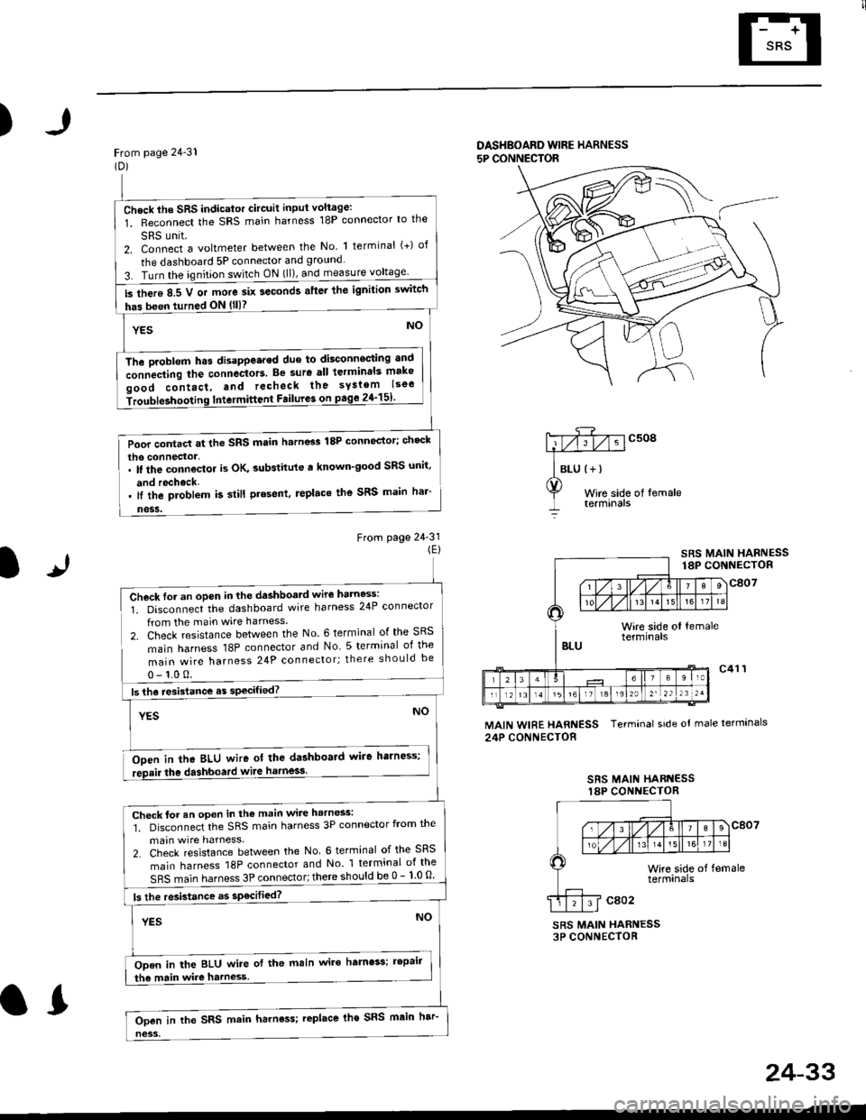
From page 24-31(Dl
DASHBOARD WIBE HARNESS
5P CONNECTOR
Wire side of temaletermtnars
From page 24-31(El
lr
SRS MAIN HARNESS18P CONNECTOR
Check for an open in the dashboatd wir€ harness:
1. Disconnect the dashboard wire harness 24P connector
from the main wire harness.
2. Check resistance between the No. 6 terminal of the SRS
main harness 18P connector and No 5 terminal of the
main wire harness 24P connector; there should be
0- 1.0 0.
Ooen in tha BLU wire ot the dashboard wire harness;
the dashboard wiie harness.
MAIN WIRE HARNESS Terminal side ot male termlnals
24P CONNECTOR
SRS MAII{ HARI{ESSlaP CONI{ECTOR
SRS MAIN HARNESS3P CONNECTOR
Check lho SRS indicator Gircuit input voliage:
1. Reconnect the SRS main harness 18P connector lo the
SRS unit.2. Connect a voltmeter between the No. 1 terminal (+) of
the dashboard 5P connector and ground
3. Turn the ignition switch ON (ll), and measure
ls there 8.5 V or more six seconds after lhe ignilion switch
has been turned ON (lll?
The Droblem h.s disappe.red due to disconnecting antl
connecting the connectors. Be sure all lerminals mako
oood contact, and recheck the syslem lsoe
iroubleshooting Intermittent Failure3 on page 2{-151'
Poor contact at the SRS main h.rn6s 18P connector; ch'ck
lI the problem k still present, replace the SRS main har'
Check for an open in the main wire harness:
1. Disconnect the SRS main harness 3P connector from the
main wire harness.
2. Check resistance between the No 6 terminal of the SRS
main harness 18P connector and No 1 terminal of the
SRS main harness 3P connector; there should be 0 - 1 0 o
ls the resistance as sp€cilied?
ODen in the BLU wire of the main wire hamess; tepair
the main wire harness.
Ooen in the SRS main harness; replace lhe SRS main har
24-33
.L
Page 1773 of 2189
)
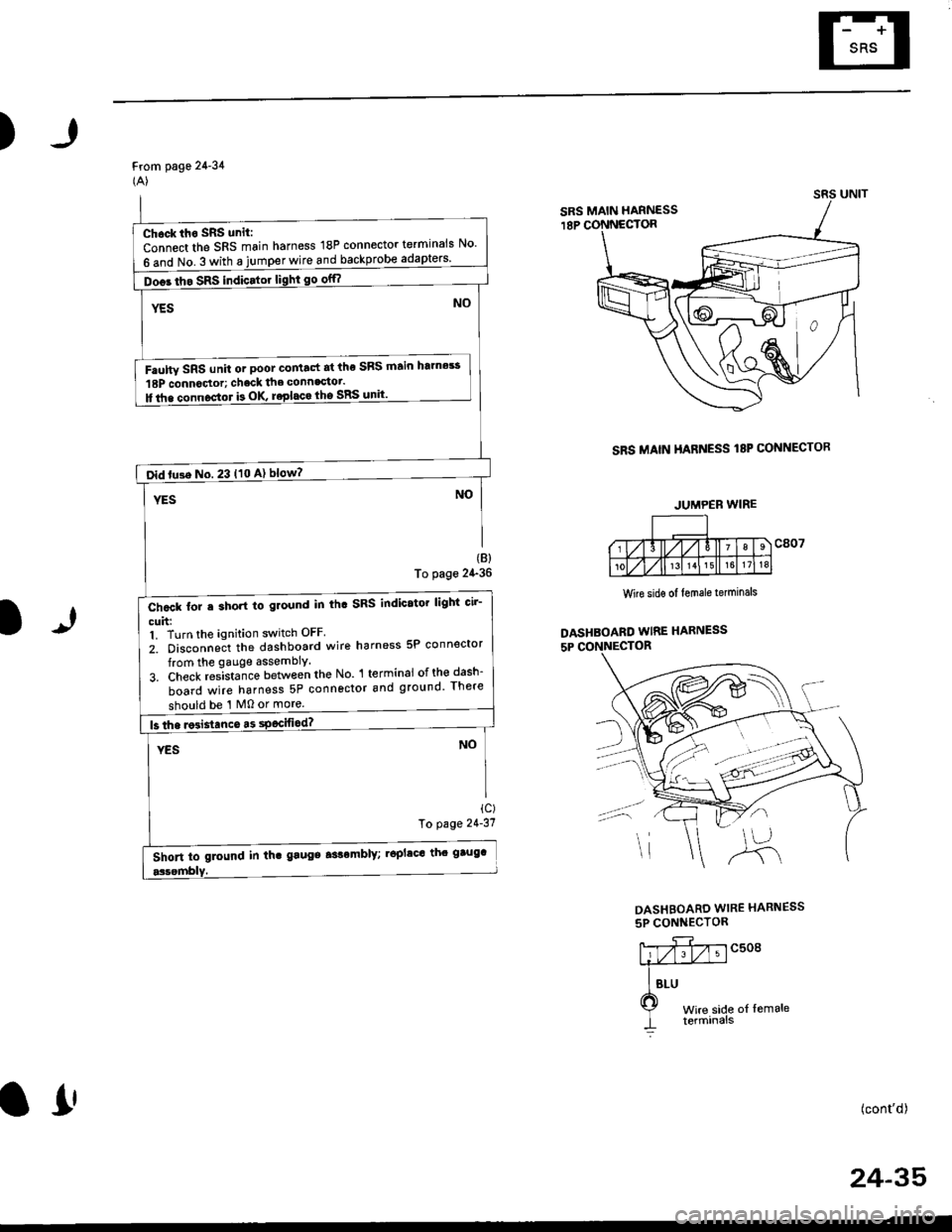
From page 24-34(A)
SRS MAIN HARNESS I8P CONNECTOR
(B)
To page 24-36
1)
Wire sidg of lemale terminals
DASHBOARD WIRE HARNESS
5P CONNECTOR
ic)To page 21'31
DASHBOARD WIRE HARNESS
5P CONNECTOR
c508
t of lemale
(cont'd)
24-35
SRS MAIN HARNESS
Chock iho SRS unit:
Connect the SRS main harness 18P connector terminals No'
6 and No. 3 with a jumper wire and backprobe
Doos tho SRS indicator light go off?
Faulw SRS unit or poot co tact at the SRS ftain htmes!
18P connoctor; chack the connagtot.
ll tha connoctor b OK roplaca lho SRS unit'
oid tu3e No. 23 t10 A) blow?
Chcck for e short to ground in th. SRS indicator lighi cir-
cuh:1. Turn the ignition switch OFF
2. Disconneit the dashboard wire harness 5P connector
from the gauge assembly.
3. Check res-ista;ce between the No l terminai ofth€dash-
board wire harness 5P connector and ground There
should be '1 M0 or more.
Short to glound in th. gaugs aslomblY; .6plac' th' gtug'
JUMPEB WIRE
o!
Page 1775 of 2189
)
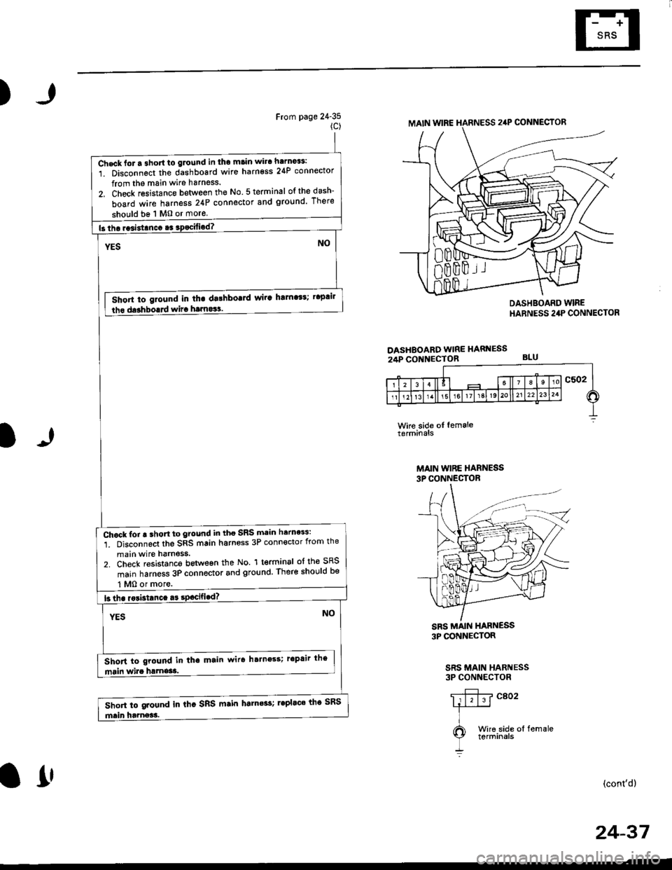
From page 24-35(c)
DASHEOARD WIRE HARNESS24P CONNECTOR
DASHBOARD WIREHARNESS 24P CONNECTOR
BLU
l)
Wke side oI femaleterminals
MAIN WIBE HARNESS3P CONNECTOR
3P CONNECTOR
SRS MAIN HARNESS3P CONNECTOR
(cont'd)
MAIN WIRE HARNESS 24P CONNECTOR
Check lor a 3hort to glound in tho main wira harno$:
1. Disconnect the dashboard wire harness 24P connector
from the main wire harness.
2, Check resistance between the No 5 terminal ofthedash-
board wire harness 24P connector snd ground There
should be 1 M0 or more
Short to giound in tha dalhbo!]d wir! ha]n'$; t'plil
lho darhborrd wira hrrnos!.
Chock for ! shon to ground in tho SRS main herness:
1. Disconnect the SRS main harness 3P connector from the
main wire harness.2. Check resistanco botween the No. 1 terminal of the SRS
main harness 3P connector and ground, There shor,lld be
Short to ground in tha main wir6 hainoss; r'Prir the
Short to ground in thc SRS main harn6s; leplac' th' SRS
l1'
24-37
Page 1776 of 2189
Troubleshooting
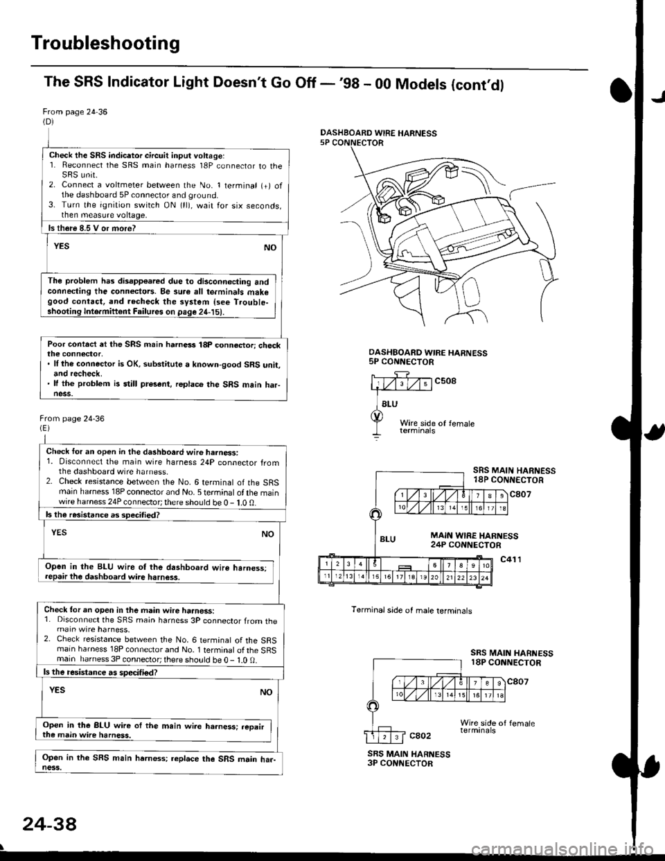
The SRS Indicator Light Doesn't Go Off -'98 - 00 Models (cont'dl
From page 24 36(D)
Check the SRS indicetor circuit input voltage:1. Reconnect the SRS main harness l8P connector to theSRS unit.2. Connect a voltmeter between the No. 1 terminal (+) ofthe dashboard 5P connector and ground.3. Turn the ignition switch ON (ll), wait for six seconds,then measure voltage,
ls th€re 8.5 V or more?
YESNO
The problem has disapp€ared due to di3connecting andconneding the connectors. Be su.e all te.minals makegood contact, and recheck the system {see T.ouble-shooting Inte.miftent Failures on page 24-15).
Poor contact et the SRS main harnass 18p connactori checkthe connector,. ll the connector is OK, substitute a known-good SRS unit,and recheck.' It the problem is still present, replace the SRS main haFness.
From page 24-36
Check for an open in the dashboard wir6 harness:1. Disconnect the main wire harness 24P connector fromthe dashboard wire harness.2. Check resistance between the No. 6 terminal of the SRSmain harness 18P connector and No. 5 terminal of the mainwire harness 24P connector; there should be 0 - 1.0 0.
ls the resistance as 3pecitied?
YESNO
Open in the BLU wire ot the dashboard wire harness;repair the dashboard wire harness.
Check tor an open in the main wire haanoss:1. Disconnect the SRS main harness 3P connector from themain wire harness.2. Check resistance between the No. 6 termanal of the SRSmain harness 18P connector and No. 1 terminal of the SRSmain harness 3P connector; there sho!ld be O - l.O 0.
ls the resistance a! specified?
YESNO
Open in the BLU wire of the m.in wire ha.ness: .eoairthe main wire harness.
Open in the SFS main hrrness; replace the SRS main har-ness.
DASHBOARD WIRE HARNESS5P CONNECTOR
c508
Terminal side of male lerminals
SRS MAIN HARNESS18P CONNECTOR
c807
c41 l
SRS MAIN HARNESS18P CONNECTOR
cao2
SRS MAIN HARNESS3P CONNECTOR
24-38
\
DASHBOARD WIRE HARNESS
Page 1809 of 2189
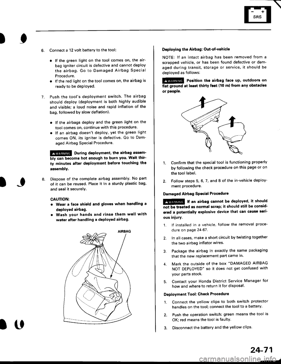
E-
)I
Connect a 12 volt battery to the tool:
. lf the green light on the tool comes on, the aar-
bag igniter circuit is defective and cannot deploy
the airbag. Go to Damaged Airbag Special
Procedure.
. lf the red light on the tool comes on, the airbag is
ready to be deployed.
Push the tool's deployment switch. The airbag
should deploY (deployment is both highly audible
and visible; a loud noise and rapid inflation of the
bag, followed by slow deflation).
. lf the airbags deploy and the green light on the
tool comes on. continue with this procedure.
. l{ an airbag doesn't deploy, yet the green light
comes ON, its igniter is defective. Go to Dam-
aged Airbag Special Procedure.
!!@ During doployment, the airbag sssom'
bly can become hot enough to buln you. Wait thir'
ty minutes aftsr deployment belore touching tho
assembly.
Dispose of the complete airbag assembly. No part
of it can be reused. Place it in a sturdy plastic bag,
and seal it securelY,
CAUTION:
. Wear a fsce shield and gloves when handling a
deployed airbag.
. Wash your hands and rinse them well with
wat6r after handling. deployed airbag.
t('
24-71
7.
AIRAAG
Doploying th6 Airbag: Out-of-vehicle
NOTE: lf an intact airbag has been removed from a
scrapped vehicle. or has been found defective or dam-
aged during transit, storage or service, it should be
deployed as follows:
@ Po3ition the airbag laca up, outdoors on
flat ground at lsast thirty f€€t (t0 ml from any obstacles
or people.
1. Confirm that the special tool is tunctioning properly
by following the check procedure on this page or on
the tool label.
2. Follow steps 5, 6, 7, and I of the in-vehicle deploy-
menl Drocequre.
Damaged Airbag Spacial Procedure
!@ r an airb.g cannot be deployed, it should
iiiTi-treatcd as normal scrap; il should still be consid-
srsd a potontially oxplosive device that can cau3o ssti-
ous iniury.
1. lf installed in a vehicle, lollow the removal proce-
dure on page 24-67.
2. In all cases. make a short circuit by twisting together
the two airbag inflator wires.
3. Package the airbag in exactly the same packaging
that the new replacement part came in.
4. Mark the outside of the box "DAMAGED AIRBAG
NOT DEPLOYED" so it does not get confused with
your Parts stock.
5. Contact your Honda District Service Manager for
how and where to return it for disposal.
Deployment Tool: Check Procedur€
1. Connect the yellow clips to both switch protector
handles on the tool; connect the tool to a battery.
2. Push the operation switch: green means the tool is
OK: red means the tool is faulty
3. Disconnect the battery and the yellow clips.
Page 1819 of 2189
How To Use This Manual
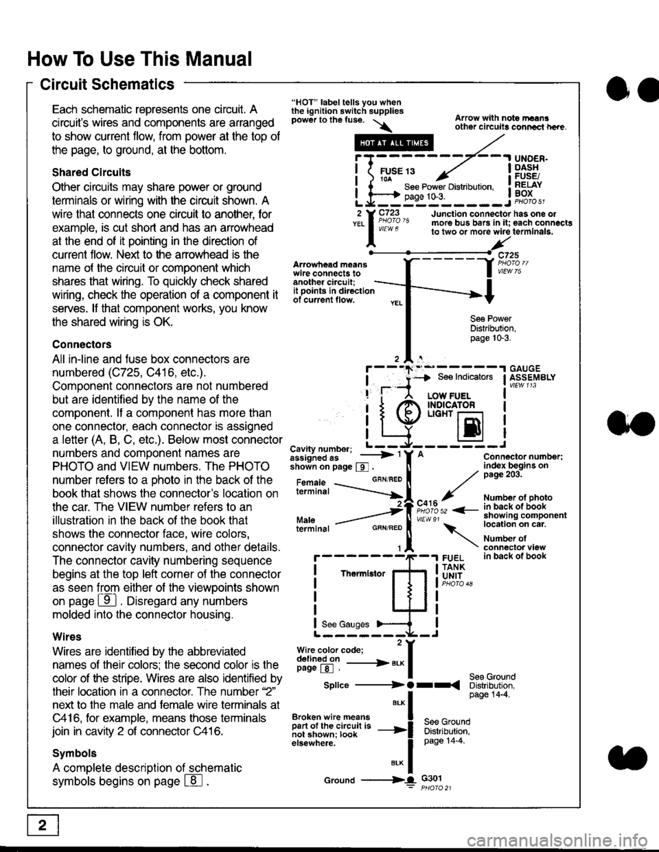
Circuit Schematics
oa
Each schematic represents one circult. A
circuit's wires and components are arranged
to show current flow, from power at the top of
the page, to ground, at the bottom.
Shared Circuits
Other circuits may share power or ground
terminals or wiring with the circuit shown. A
wire that connects one circuit to another, for
example, is cut short and has an arrowhead
at the end of it pointing in the direction of
current flow. Nelit to the anowhead is the
name o{ the circuil or comoonent which
shares that wiring. To quickly check shared
wiring, check the operation of a component it
serves. lf that component works, you know
the shared wiring is OK.
Connectors
All in-line and fuse box connectors are
numbered (C725, C416, etc.).
Component connectors are not numbered
but are identiJied by the name of the
component. lf a componenl has more than
one connector, each connector is assigned
a letter (A, B, C, etc.). Below most connector
numbers and comDonent names are
PHOTO and VIEW numbers. The PHOTO
number refers to a Dhoto in the back of the
book that shows lhe conneclor's location on
the car. The VIEW number refers to an
illustration in the back of the book that
shows the connector face, wire colors,
connector cavity numbers, and other details.
The connector cavity numbering sequence
begins at the top left corner oJ the connector
as seen from either of the viewooints shown
on page ffl . Disregard any numbers
molded into the connector housino.
Wires
Wires are identilied by the abbreviated
names of their colors; the second color rs the
color of the stripe. Wires are also identified by
their location in a connector. The number '2"
next to the male and female wire terminals at
C416, for example, means those terminals
join in cavity 2 of connector C416.
Symbols
A complete description of schematic
symbols begins on page | 8
"HOT" label tells you whenthe ignition switch suppliespower to the fuse. \
Artowhead meanswire connects toanother circuit;
Arrow with note rErngother circuils conncct h€re.
it .a
llu":: ^,{ ii t See Power Distribution, .I t----t oaqe tO-3. IL*--:--------J2 Y C723 Junction connectorYEL I Pao'o'8 more bus bars in it;
I - " " to two or more wire
l,/
-t>?
See PowerDistribution,page 10-3.
UNDER.DASHFUSE/RELAYBOX
has one oleach connactgterminala.
it ooints in directionof current flow.
TheImletor
t_I
Cavity number; L ---
Jiili'iJi!--' -----> '
shoin on page S .
Maleterminal
L?*?l?,-
"'"'I
c725
vlEUt/ 75
Connector number;index begins onpage 203.
Number ot photoin back ol bookshowing componentlocation on cat.
Number ofconneclor viewin back of book
7
GBN/FEO
See Ground
Soe Indicators I ASSEMBLY
:-------J
LOW FUELINDICATOFLIGHT r-l
EI
A
"o'r"/PHOTO 52 <-
\
FUELTANKUNIT
Splice ---------) O rr
".* I Page 14'4'
IBroken wire means | --^ -
iar";J.'It,;,rJ;ii; -----i Bffi,Bili*l
elsewhere. I 0a0e tn-a
IBrK Icround --->lL c301: ptioro 21
Page 1825 of 2189
How To Use This Manual
Symbols
oo
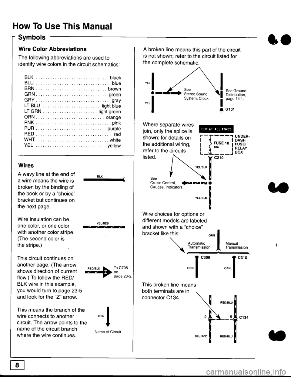
Wire Color Abbreviations
The following abbreviations are used to
identify wire colors in the circuit schematics:
BLK.... .........b|ack
BLU.... ......... blue
BRN.... ,....... brown
GRN.... ........ green
GRY.... ......,.. gray
LTBLU . .....lightbtue
LTGRN. ....lightgreen
ORN.... ....... orange
PNK .... .......,.. pink
PUR .... ........ purple
RED .... .......... red
WHT... .........white
YEL .... ........ yellow
A broken line means this part of the circuit
is not shown; refer to the circuit listed for
the complete schematic.
"ral
o
-.1
See GroundDistribution,page 141.
I G101
Where separate wires
join, only the splice is
shown; for details on
the additional wiring,
refer to the circuits
listed.ili::i
{[
UNDER-OASHFUSE/RELAYBOX
Wires
A wavy line at the end of
a wire means lhe wire is
broken by the binding of
the book or by a "choice"
bracket but continues on
the next page.
Wire insulation can be
one color, or one color
with another color stripe.
(The second color is
the stripe.)
This circuit continues on
another page. (The arrow
shows direction o{ current
flow.) To tollow the RED/
BLK wire in this example,
you would turn to page 23-5
and look for the "2" anow.
This means the branch of the
wire connects to another
circuit. The arrow Doints to the
name of the circuit branch
where the wire continues.
8LK-Cruise Control, €�aaaGauges, Indrcalors
!YEUsLK
Ttl
Wire choices for options or
different models are labeled
and shown with a "choice"
bracket like this.
This broken line means
both terminals are in
connector C134.
a.
+##l:i""lManuallransmission
ryil;::,
.""1
""'
"""1".'0
I
""^l
:-lName of Circuit
Page 1827 of 2189
How To Use This Manual
Symbols
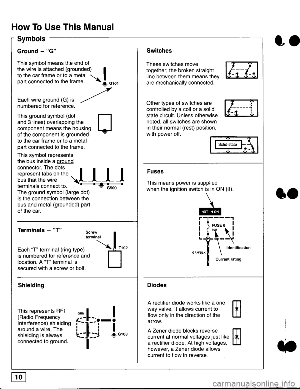
Ground - "G"
This symbol means the end ol
the wire is attached (grounded) Ito the car frame or to a metal I
part connected to the frame. \i oro,|
-t'
Each wire ground (G) it --/
numbered for reference.
oo
Switches
These switches move
together; the broken straight
line between them means the,
are mechanically connected.
Other types of switches are
controlled by a coil or a solid
state circuit. Unless otherwise
noted. all switches are shown
in their normal (rest) position,
with power off.
This ground symbol (dot
and 3 lines) overlapping the
component means the housing
of the component is grounded
to the car frame or to a metal
part connected to the frame.
This symbol represents
the bus inside a ground
connector. The dots I
i:l*,':1,'^:*,:"
;"
r"L I I I
terminals connect to.
The ground symbol (large dot)
is the connection between the
bus and metal (grounded) part
of the car.
Terminals - "T"
ffi
ffi
Solid-state
Fuses
This means power is supplied
when the ignition switch is in ON (ll).
Current rating
Diodes
A rectifier diode works like a one
way valve. lt allows current to
llow only in the direction of the
arrow.
A Zener diode blocks reverse
current at normal voltages just like
a rectifier diode. At high voltages.
however, a Zener diode allows
current to f low in reverse
oo
Each "T" lerminal (ring type)
is numbered for reference and
location. A "T" terminal is
secured with a screw or bolt.
Shielding
This represents RFI
(Radio Frequency
Interference) shielding
around a wire. The
shielding is always
connected to ground.
f--l;j-i",..
I
,,,,
T