Page 1983 of 2189

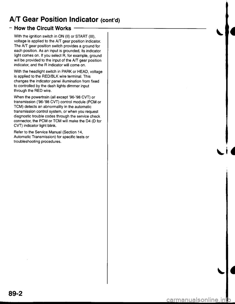
A/T Gear Position Indicator (conrd)
- How the Circuit Works
With the ignition switch in ON (ll) or START (lll),
voltage is applied to the A,/T gear position indicator.
The A,/T gear position switch provides a ground for
each position. As an input is grounded, its indicator
light comes on. lf you select R, for example, ground
will be provided to the input of the A,/T gear position
indicato( and the R indicator will come on.
With the headlight switch in PARK or HEAD, voltage
is applied to the RED/BLK wire terminal. This
changes the indicator panel illumination from fixed
to controlled by the dash lights dimmer input
through the RED wire.
When the powertrain (all except '96-'98 CVT) or
transmission ('96198 CVT) control module (PCM or
TCM) detects an abnormality in the automatic
transmission control system, or when you request
diagnostic trouble codes through the service check
connector, the PCM or TCM will make the D4 (D for
CVT) indicator light blink.
Refer to the Service Manual (Section 14,
Automatic Transmission) for specific tests or
troubleshooting procedures.
\ia
89-2
Page 1992 of 2189
Back-Up Lights
- Coupe and Sedan
*=Male-Female
terminals reversedfor '99100 models
!, (
I
10
YEURED
UNDER.DASHFUSE/RELAYBOXPHOfO 58
T
I:c,
x
FUSE 19EACK UF UGH'S754
-----Jc419
A/T except CW
YEUNEO
15('99-'00 except D16Y5 6)
YEL
2
GRN/BLK
c'13't
vlEw 59
c124PHOTO 31PHOrO 150 (Si)
vtEw 59
BACK-UPLIGHT SWITCHClosed withtransmissionin reverse.
PHO|O 75r (SD
cl24
PHOTO 15015)
3 ^ C433
yeL a VIEW 41.I A/T GEAR:+f't::
tDa
l!-iAf
;;-'i-
""",":lt
'lrry
lD.
ly*Af
:t
| | | ?osllrgN
i l"-3.^' a "s#[c#i "j!*{b. i*'o*
GFN/BLK
GRN/BIX
14('99100 except 016Y5 18)
CRN/BL(
aplF--1 i';".;t---'
o * "",0::","
o"n,".-*
[
u't' o '
!(
'99-'00
S€dan$
t gg- oo mooers l2ot | #:;",,
, rrr:eS;f""t"-!# I ;; tAll oxcept'9$'oo Sodans
"*^*f,
""::in;;'
ffi,*,,.T
@
GFN/BLK
lo
@FLRI''
"*r
>-rO
@i[TJ+."
RIGHTBACK.UPLIGHT
22
See GroundDistribution,pags 1i1.1t.
".- |
!
I
Ia
I
!G601G601
PHO|O 102 IAX)
110
(
Page 2054 of 2189

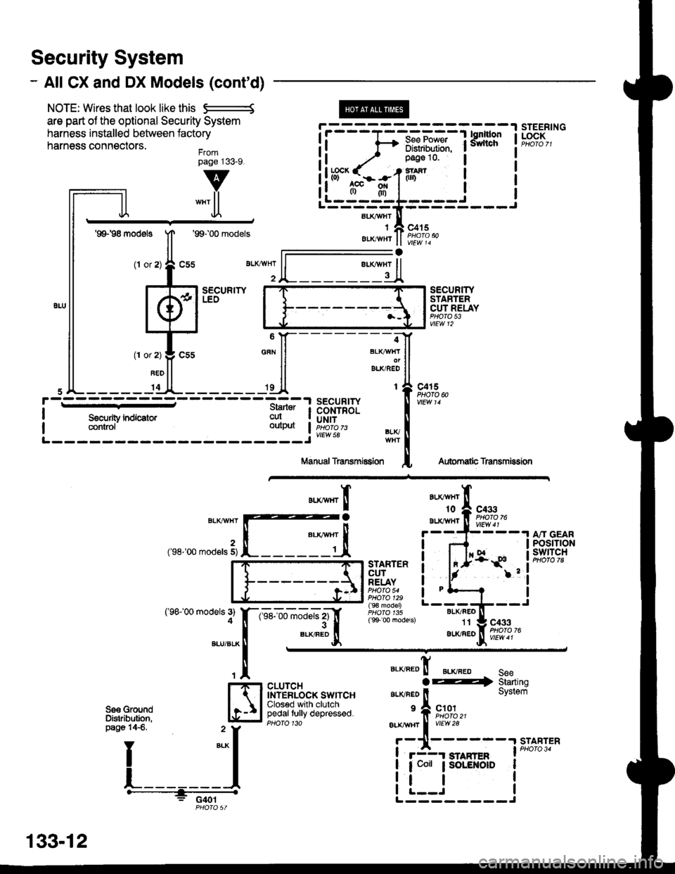
Security System
- All CX and DX Models (cont'd)
NOTE: Wires that look like this S--------S
are part ol the optional Security System
harness installed between lactory
harness connectors.Frompage j33_9.
@
aLI(AVHI
IAIKWHT
STEERINGLOCK
v
""'ll
'99198 models
(l or
1T
Jl.
'99100 models
sEcuRrwLEO
c415
vlEw 14
l-
SECURITYSTARTERCUT RELAYPHO|O 53vtEw 12
BLI(FEO't1
au(/FEo
c433
Aubrnatb Transmission
c4r 5PHOTO N
AU(WHT't0
BLXAVI{TBLKT'!VHT
2('98-'00 mod€ls 5)
('98100 models 3)4
A"IT GEARPOStTTONswtTcH
".**"rI
[ :,iSTARTERCUTRELAYPHO|O 54PHO|O 129( 9€ model)
( 9+ 00 models)
?
I
I
I
I
I
1-sel-oo rnJ"ls z1'[
".*"9tr
c433
CLUTCHINTERLOCK SWITCHClosed with clutchpedaltully depressed.
".o""0! ".o".0 seeaE4 Starting
ar-rvneo ll System
'f, "";%,,BLK TTBT I
vrEw28
r-11------.|STABTER
! r3r smnren I PHoro 34
| 1 coit ; SoLENOID I
i !.__J iL--------J
"===-F=F*F,Ff
Tfo?"
It -,/ Pase 10 l
!ltb3'-fi:-#-1iln i
ll .",;T; "":JI------;;lt
ll *"ll ll ELKBEDII
,JL----- 'dl*------ 'll t{
paso 14€. " y
I
*-l
L_______l.------+;_ -
PHO|OST
133-12
Page 2085 of 2189
25. Lower Left Rear of Engine
Component Location
\28. Lower Right Side of Engine Compartment
26. Left Side of Engine (All Except 816A2)29. Lower Right Front of Engine
\
27. Right Front of Engine30. Lower Front of Transmission
201-4
\
Page 2100 of 2189
115. Left Side of Trunk Lid (except '99-'00 Sedan)118. Left Rear of Trunk/Cargo Area (except '99-'00 Sed.)b
\
116. Center of Trunk Lid119. Top of Transmission (CVT)
117. Rear Spoiler on Trunk Lid120. Right Side Rear of Engine Compartment (CVT)
L
ffi=
201 -19
Page 2101 of 2189
Gomponent Location
121. Behind Left Kick Panel ('96-'98 CVT)\124. Rear of Engine Compartment (CVT)
TRANSMISSIONCONTROL MODULE(rcM)
122. Right Side Lower Engine Compartment (CVT)125. Behind Right Side of Dash Panel
\
123. Right Front of Engine (CVT)126. Underside of Hatch Lid
k
2A1-20
\
Page 2106 of 2189
IO151. Lower Front of Transmission (Si)
152. Left Center of End Panel ('99-'00 Sedan)
201-25
Page 2108 of 2189

-
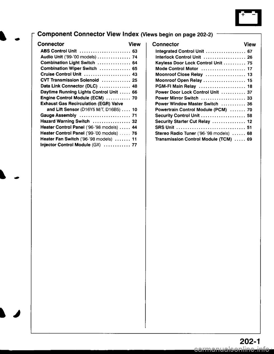
Component Connector View Index (Views begin on page 202-21
Connector View
ABS Control Unit........ ......63
Audio Unit ('99-'00 models) ......74
Combination Light Switch . . . . . . . . . . . . . . . 64
Combination Wiper Switch . . . . . . . . . . . . . . 65
Cruise Control Unit.... .....43
C\TTTransmission Solenoid ............. 25
Data Link Connector (DLC) ..... 48
Daytime Runnlng Lights Control Unit ..... 66
Engine control Module (ECM) ...........70
Exhaust Gas Recirculation (EGR) Valve
and Lift Sensor (D16Y5 Mfl, D1685) . . . . 10
Gauge Assembly .............71
HazardWarnlngSwitch,,. .,,,...,,,,... 32
Heater Control Panel ('96-'98 models) .....44
Heater Control Panel ('99-'00 models) ...., 76
Heater Fan Switch ('96-'98 models) ,,,.... 11
fniector Control Module (GX) ............77
I/
202-1
Connector View
Integrated Control Unit .......,. 67
f nterfock Control Unit .... ...... 26
Keyfess Door Lock Control Unit . . . . , . . . . . 75
Mode Control Motor ... ........'17
Moonroof Close Relay .. .......13
Moonroof Open Relay ... .......15
PGM-FI Main Relay .. .......... 18
Power Door Lock Conlrol Unil ..... ...... 37
Power Mirror Switch .,... ...... 33
Power Window Master Switch .,.........36
Powertrain Control Module (PCM) .......70
Security Control Unit ..., ..,,... 58
Security Starter Cut Belay ... ...,,,....,, 12
SRS Unit ............. 51
Stereo Radio Tuner ('96-'98 models) ...... 68
Transmission Control Module CICM) .....69