Page 1872 of 2189
, r -.-- .l TBANSMTSS|ON
I igF"
A/T Gear Position Indicator (conrd)
- How the Circuit Works
With the ignition switch in ON (ll) or START (lll),
voltage is applied to the A,/T gear position indicator.
The A,/T gear position switch provides a ground for
each position. As an input is grounded, its indicator
light comes on. lf you select R, for example, ground
will be provided to the input of the A,/T gear position
indicato( and the R indicator will come on.
With the headlight switch in PARK or HEAD, voltage
is applied to the RED/BLK wire terminal. This
changes the indicator panel illumination from fixed
to controlled by the dash lights dimmer input
through the RED wire.
When the powertrain (all except '96-'98 CVT) or
transmission ('96198 CVT) control module (PCM or
TCM) detects an abnormality in the automatic
transmission control system, or when you request
diagnostic trouble codes through the service check
connector, the PCM or TCM will make the D4 (D for
CVT) indicator light blink.
Refer to the Service Manual (Section 14,
Automatic Transmission) for specific tests or
troubleshooting procedures.
\ia
89-2
Page 2108 of 2189

-
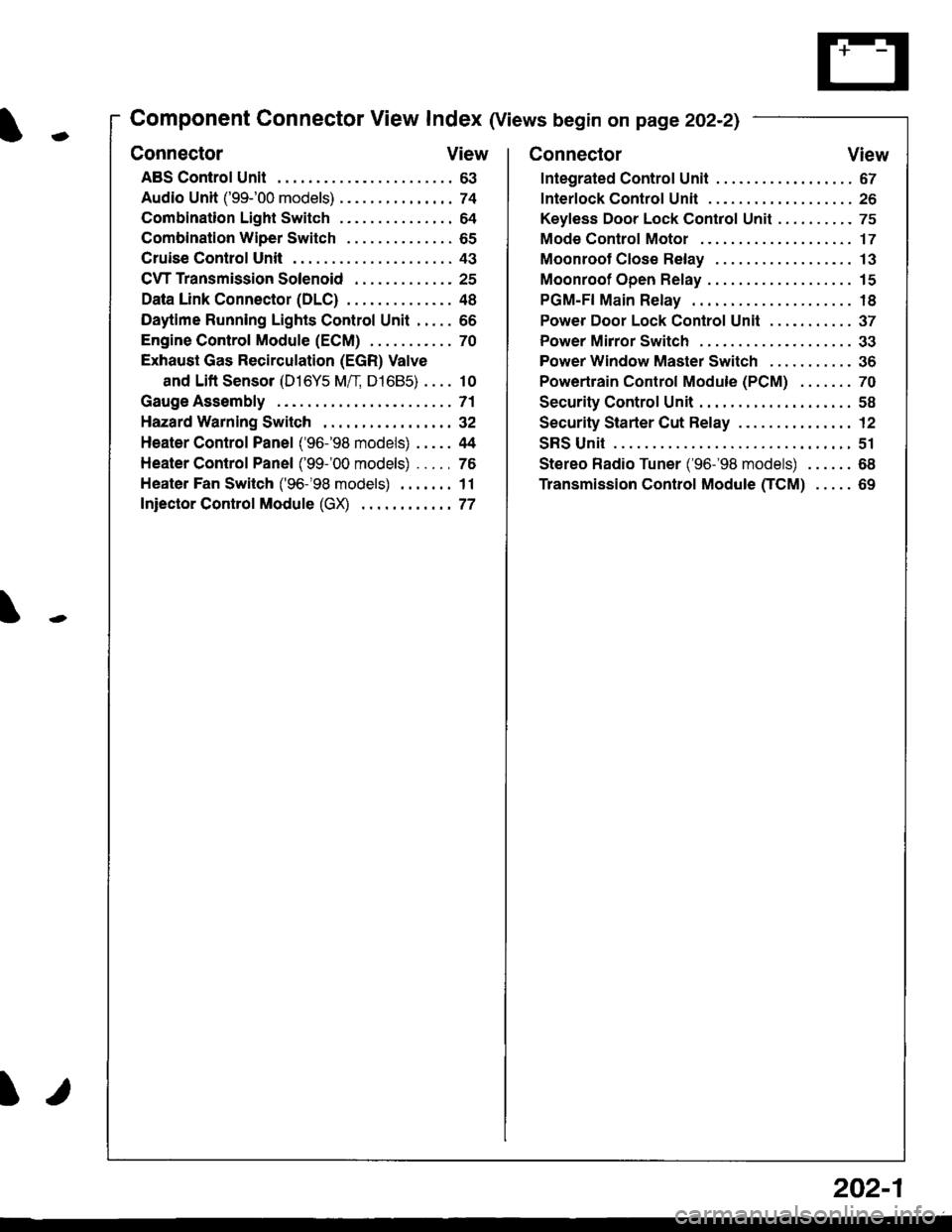
Component Connector View Index (Views begin on page 202-21
Connector View
ABS Control Unit........ ......63
Audio Unit ('99-'00 models) ......74
Combination Light Switch . . . . . . . . . . . . . . . 64
Combination Wiper Switch . . . . . . . . . . . . . . 65
Cruise Control Unit.... .....43
C\TTTransmission Solenoid ............. 25
Data Link Connector (DLC) ..... 48
Daytime Runnlng Lights Control Unit ..... 66
Engine control Module (ECM) ...........70
Exhaust Gas Recirculation (EGR) Valve
and Lift Sensor (D16Y5 Mfl, D1685) . . . . 10
Gauge Assembly .............71
HazardWarnlngSwitch,,. .,,,...,,,,... 32
Heater Control Panel ('96-'98 models) .....44
Heater Control Panel ('99-'00 models) ...., 76
Heater Fan Switch ('96-'98 models) ,,,.... 11
fniector Control Module (GX) ............77
I/
202-1
Connector View
Integrated Control Unit .......,. 67
f nterfock Control Unit .... ...... 26
Keyfess Door Lock Control Unit . . . . , . . . . . 75
Mode Control Motor ... ........'17
Moonroof Close Relay .. .......13
Moonroof Open Relay ... .......15
PGM-FI Main Relay .. .......... 18
Power Door Lock Conlrol Unil ..... ...... 37
Power Mirror Switch .,... ...... 33
Power Window Master Switch .,.........36
Powertrain Control Module (PCM) .......70
Security Control Unit ..., ..,,... 58
Security Starter Cut Belay ... ...,,,....,, 12
SRS Unit ............. 51
Stereo Radio Tuner ('96-'98 models) ...... 68
Transmission Control Module CICM) .....69
Page 2133 of 2189

Connector Views (cont'd)
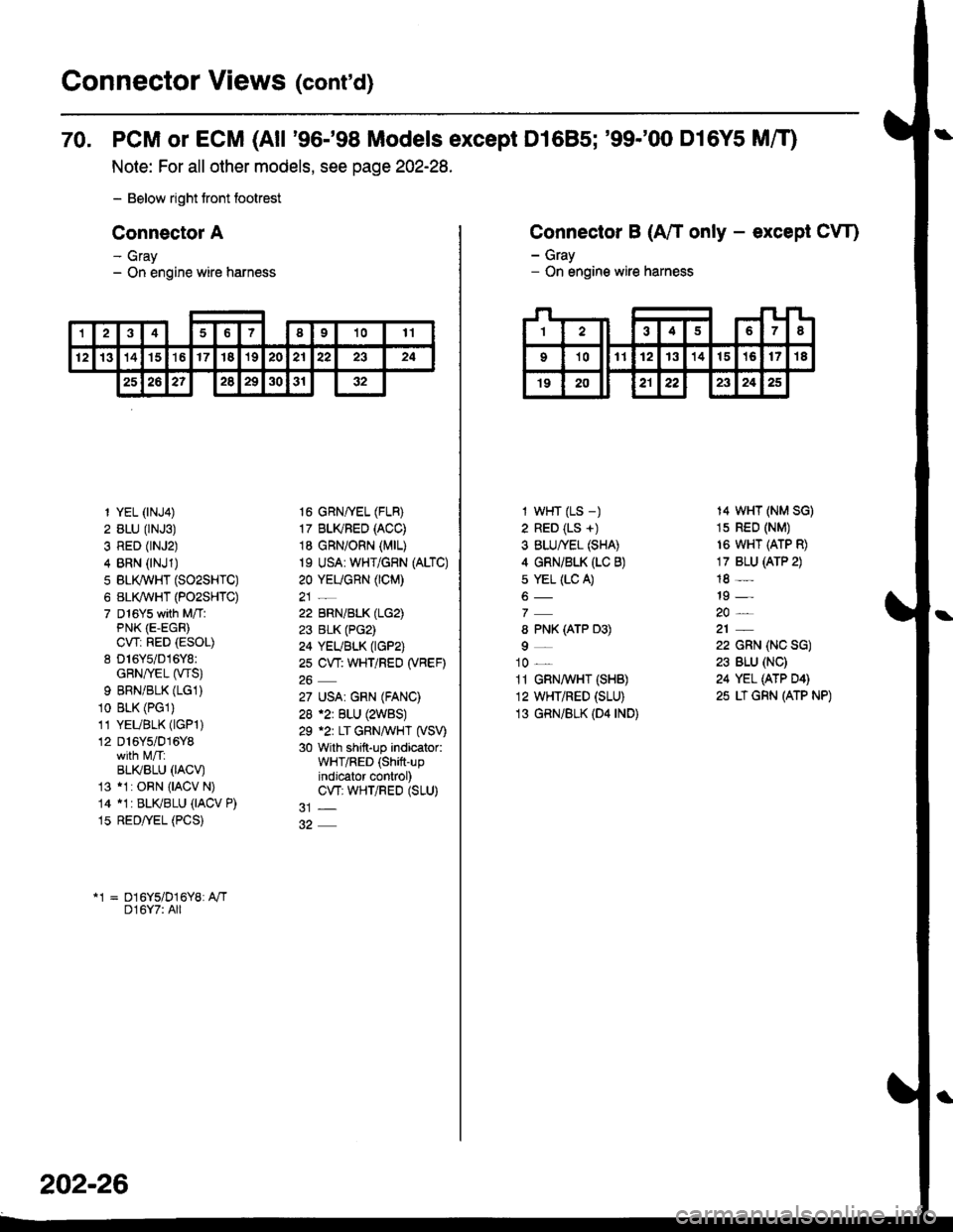
70. PCM or ECM (All '96-'98 Models except D1685; '99-'00 D16Y5 MfO
Note: For all other models, see page 202-28.
- Below right tront footrest
Connector A
- Gray- On engine wire harness
12346I91011
12131415't617'182021222324
25262?2829303'r32
1 YEL (rNJ4)
2 BLU (rNJ3)
3 RED (rNJ2)
4 BRN (NJ1)
5 BLI(WHT (SO2SHTC)
6 BL(WHT (PO2SHTC)
7 D16Ys with M/TlPNK (E-EGR)
CWi RED (ESOL)
8 D16Y5/016Y8:GRN/rEL (wS)
9 BRNiBLK (LG1)
10 BLK (PGl)
11 YEUBLK (lGPl)
12 D16Y5/016Y8
BLI(BLU 0ACV)13 11: ORN {IACV N)
14 11r BLKBLU (IACV P)
15 RED/yEL (PCS)
16 GRNffEL (FLB)
17 BLI(FED (ACC)
18 GRN/ORN (MrL)
19 USA: WHT/GRN (ALTC)
20 YEUGnN (CM)
22 BRN/BLK (LG2)
23 BLK (PG2)
24 YEUBLK (tGP2)
2s CW: WHT/REO (VBEF)
27 USA| GRN (FANC)
28 .2r BLU (2WBS)
29 .2r LT GRNAVHT (VSV)
30 with shift-up indicator:WHT/RED (Shift-upindjcator control)CW; WHTiRED (SLU)
*1 = D16Y5/D16Y8: A"/TD16Y7: All
202-26
Connector B (A/T only - except CW)
- Gray- On engine wire harness
I wHT (LS -)
2 RED (LS +)
3 BLU/YEL (SHA)
4 GRNi BLK (LC B)
s YEL (LC A)
8 PNK (ATP D3)
9_
10 _
11 GRN,4 HT (SHB)
12 WHT/RED (SLU)
13 GRN/BLK (D4 rND)
14 WHT (NM SG)
1s RED (NM)
16 WHT (ATP R)
17 BLU (ATP 2)
18 -
19 -
22 GRN (NC SG)
23 BLU (NC)
24 YEL (ATP D4)
25 LT GRN (ATP NP)
Page 2135 of 2189

Connector Views (conrd)
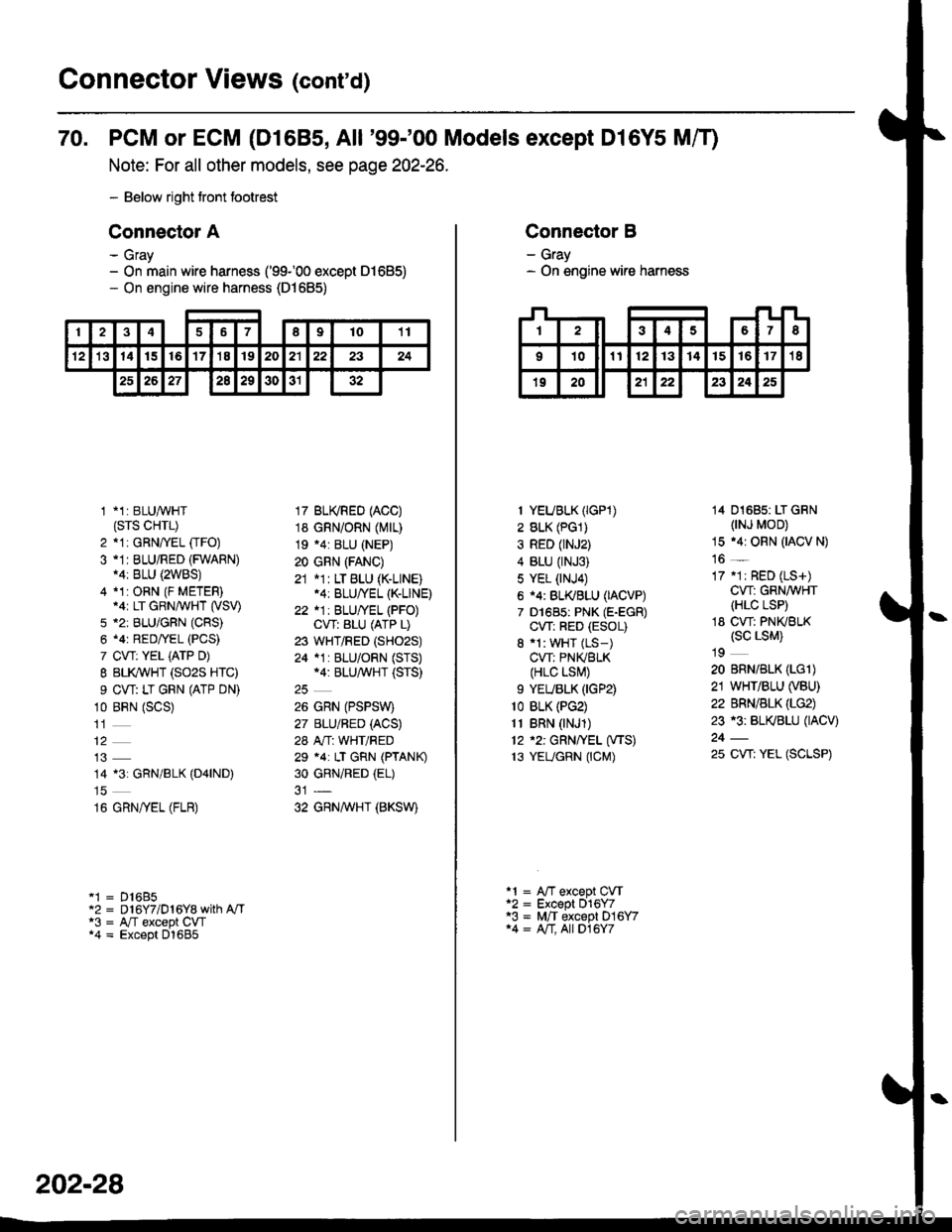
70. PCM or ECM (D1685, All '99-'00 Models except Dl6Y5 Mff)
Note: For all other models, see page 202-26.
- Below right tront footrest
Connector A
- Gray- On main wire harness ('99100 except 01685)- On engine wire harness (D1685)
246789t011
't21314t516'17'18192021222324
2526272a29303132
1 *1: BLUAVHT(srs cHrL)
2 *1: GRNffEL [rFO)3 -1I BLU/RED (FWARN)14: BLU {2WBS)4 *1:ORN (F METER).ar LT GRN/WHT (VSV)
5 *2: BLU/GFN (CRS)
6 .4r RED/YEL (PCS)
7 CVT: YEL iATP D)
I BLI(WHT (SO2S HTC)
9 CW: LT GRN (ATP DN)
10 BRN (SCS)
14 13: GRN/BLK (D4|ND)
16 GRN/yEL (FLR)
'1 = D16B5"2 = D 16Y7/D 1 6Y8 with A"/Ta3 = A,/T except CW*4 = Except D1685
17 BU(RED (ACC)
18 GRN/ORN (Mrr)
19 .4: BLU (NEP)
20 GRN (FANC)
21 *1: LT BLU (K-LINE).4: BLU/YEL (K-LINE)
22 *1: BLU/YEL (PFO)CVT: ALU (ATP L)
23 WHT/RED (SHO2S)
24 *1 : BLU/ORN (STS)*4: BLU/^,iVHT (STS)
26 GRN (PSPSW)
27 BLU/BED (ACS)
28 A"/T: WHT/RED
29 *4: LT GRN (PTANK)
30 GRNiRED (EL)
32 GRNAVHT (BKSW)
202-28
Connector B
- Gray- On engine wire harness
I YEUBLK (IGP1)
2 BLK (PG1)
3 RED (rNJ2)
4 BLU (rNJ3)
5 YEL (NJ4)
6 i4: BL(BLU (IACVP)
7 D1685: PNK (E-EGR)
CW: RED (ESOL)
8 'l: WHT (LS-)
CVT: PNIVBLK(HLC LSI\,!)
9 YEUBLK (IGP2)
1o BLK (PG2)
11 BRN (NJ1)
12 '2: GRN/YEL (VTS)
13 YEUGRN (CM)
14 01685: LT GRN(NJ MOD)
15 .4r ORN (IACV N)
16 _
17 .1r RED (LS+)
CW: GRN/WHT(HLC LSP)
18 CW: PNKBLK(sc LsM)
19
20 BRN/BLK (LGl)
21 WHT/BLU (VBU)
22 BRN/BLK (LG2)
23 r3: BL(BLU (IACV)
25 CW: YEL (SCLSP)
a1 = A"fT except CVTa2 = Except 016Y7'3 = M,/T except D16Y714 = A/T, All D16Y7