1999 HONDA CIVIC wheel alignment
[x] Cancel search: wheel alignmentPage 1132 of 2189
Front Suspension
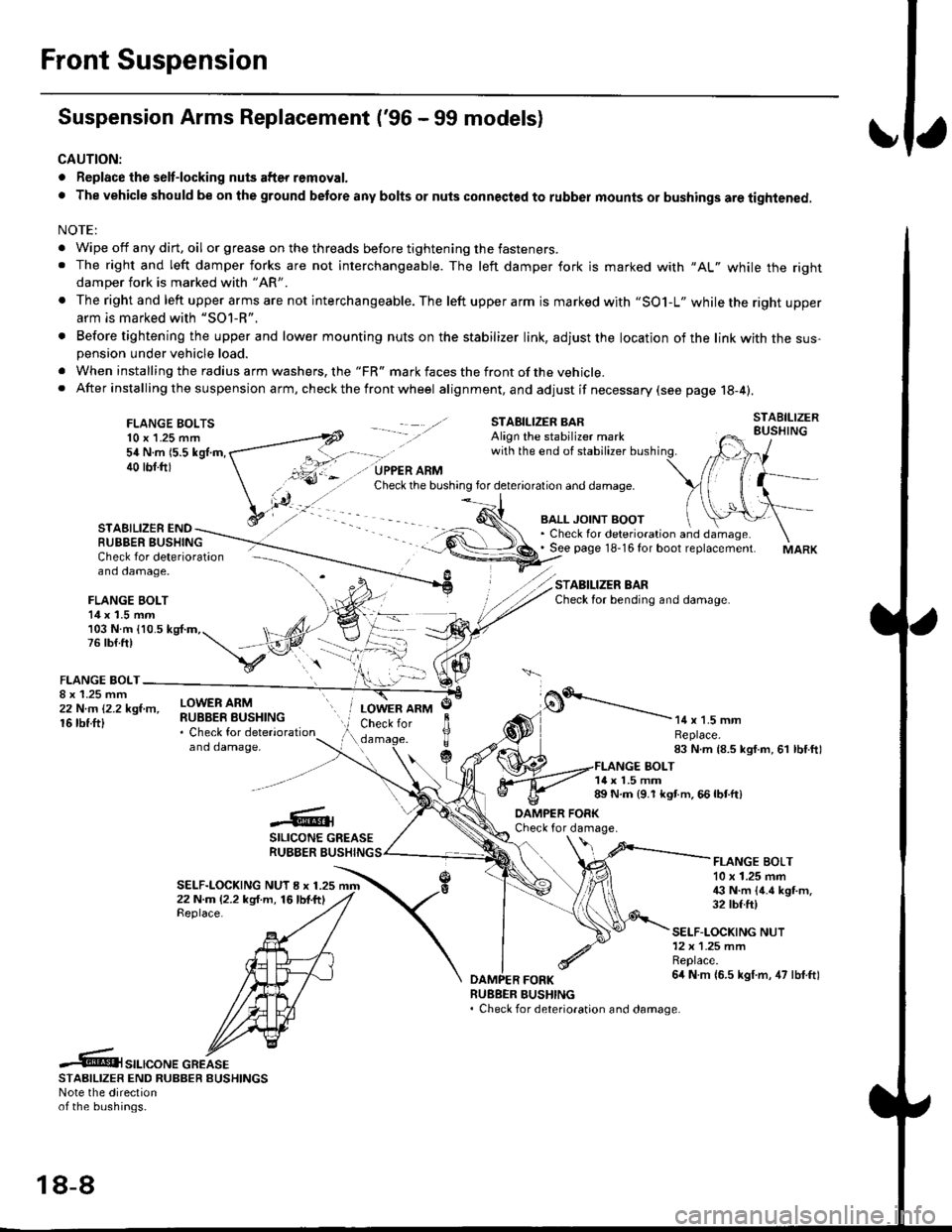
Suspension Arms Replacement ('96 - 99 models)
CAUTION:
. Replace the selt-locking nuts after removal.
. The vehicle should be on the ground betore any bolts or nuts connected to rubber mounts or bushings are tightened.
NOTE:
. Wipe off any dirt, oil or grease on the threads before tightening the fasteners.. The right and left damper forks are not interchangeable. The left damper fork is marked with "AL" while the rightdamper fork is marked with "AR'
. The right and left upper arms are not interchangeable. The left upper arm is marked with "SO1-L" while the right upperarm is marked with "SOl-R".
. Before tightening the upper and lower mounting nuts on the stabilizer link, adjust the location of the link with the sus-pension under vehicle load.
. When installing the radius arm washers, the "FR" mark faces the front ofthe vehicle.. After installing the suspension arm, ch eck the front wheel alignment, and adjust if necessary (see page 18-4).
FLANGE BOLTS10 x 1.25 mm54 N.m 15.5 kgl.m,40 tbf.ftl
STAEILIZER ENDRUBBER BUSHING
BALL JOINT BOOT. Check for deterioration and damage.. See page 18-16 for boot replacement.
STABILIZER BARCheck for bending and damage.
Check for deterioration - ---\--
and damage, -\
FLANGE BOLT14 x 1.5 mm/)l103 N.m {10.5 kg{.m,. t, ,/4,76lb{.ft) t,,"-iV
v:\FLANGE BOLT-
;iffillr-"- ilHitffi*::,"*"
and damaoe,
o.'-----------14 x 1.5 mmReplace.83 N.m {8.5 kgf.m, 61 lbf.ftl
LOWER ARMCheck for
c
JlTTda
1{ x 1.5 mm89 N.m {9.1 kgt m. 66 lbtft)
-6;SILICONE GREASERUBBER BUSHING
DAMPER FORKCheck for damage.
SELF-LOCKING NUT I x 1.2522 N.m (2.2 kg{.m, 16lbf.ftlReplace.
FLANGE BOLT10 x 1.25 mm€ N.m {4.6 kgt m.32 tbf.ft)
SELF-LOCKING NUT12x 1.25 mmReplace.6it N m {6.5 kgf.m, 47 lbf.ftl
RUEBER BUSHING. Check for deterioration and damage.
.6t",.,"o".c"KeSTAAIL|zER END RUBBER EUSHINGSNote the directionof the bushings.
18-8
Page 1133 of 2189
I
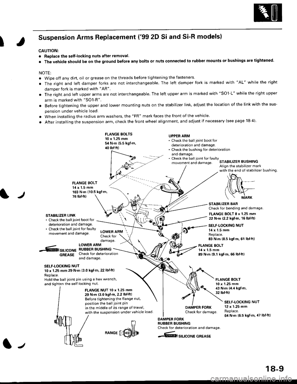
Suspension Arms Replacement ('99 2D Si and Si-R models)
CAUTION:
. Replace the selt-locking nuts after removal.
. The vehicle should be on the ground belore any bolts or nuts connected to rubber mounts or bushings are tightened.
NOTE:
. Wipe off any dirt, oil or grease on the threads before tightening the fasteners
. The right and ieft damper forks are not interchangeable. The left damper fork is marked with "AL" while the right
damper fork is marked with "AR"
. The right and left upper arms are not interchangeable. The left upper arm is marked with "SOl-L" while the right upper
arm is marked with "SO1-R".
. Before tightening the upper and lower mounting nuts on the stabilizer link, adiust the location of the link with the sus-
pension under vehicle load.
. When installing the radius arm washers, the "FR" mark faces the front of the vehicle.
. After installing the suspension arm, check the front wheel alignment, and adjust if necessary (see page 18-4).
FLANGE BOLTS10 x 1.25 mmsit N.m 15.5 kgf.m,40 tbtftl
UPPER ARM' Check the ball joint boot fordeterioration and damage.. Check the bushing for deteriorationano oamage,. Check the ball ioint fo. faultymovement and clamage.STABILIZER BUSHINGAlign the stabilizer markwith the end of stabilizer bushing
FLANGE BOLT14 x 1.5 mm
l./
103 N.m (10.5 kgf.m,76 tbr.ftl
STABILIZER LINK. Check the ballioint bootfordeterioration and damage.. Checkthe ballioint tor faultymovement and damage.
STABILIZER BARCheck for bending and damage.
FLANGE BOLT 8 x 1.25 mm22 N.m (2.2 kgf.m, 16lbf.ft)
SELF-LOCKING NUT14 x 1.5 mmReplace.83 N.m 18.5 kgf m, 61 lbf.ft)
-.6r srr-,co", hSHrtlrT.[*"u
6g619g Check for deteriorationano oamage.
SELF.LOCKING NUT10 x 1.25 mm 29 N m 13.0 kgf m, 22 lbf ftl
Replace.Hold the ball ioint pin using a hex wrench,
and taghten the self'locking nut.
LOWER ARMCheck fordamage.
FLANGE NUT l0 x 1.25 mm
29 N.m 13.0 kgI m,2.2 lbf ft)
Before tightening the {lange nut,position the ball joint Pinin the middle of its range of travel,
with the suspension under vehicle load
FLANGE BOLT14 x 1.5 mm89 N.m 19.1 kgf.m, 66 lbf.ft)
FLANGE BOLT10 x '1.25 mm43 N.m {4.4 kgf.m,32 tbtft)
DAMP€R FORKCheck lor damage.
DAMPER FORKRU88ER BUSHINGCheck for deterioration and damage.
4@lsrlrcoNE GREASE
SELF.LOCKING NUT12 x 1.25 mmReplace.64 N m 16.5 kgl.m, 47 lblft)
J
RANGE
18-9
Page 1139 of 2189
I
NOTE: Wash the knuckle and hub thoroughly in
high flash point solvent before reassembly.
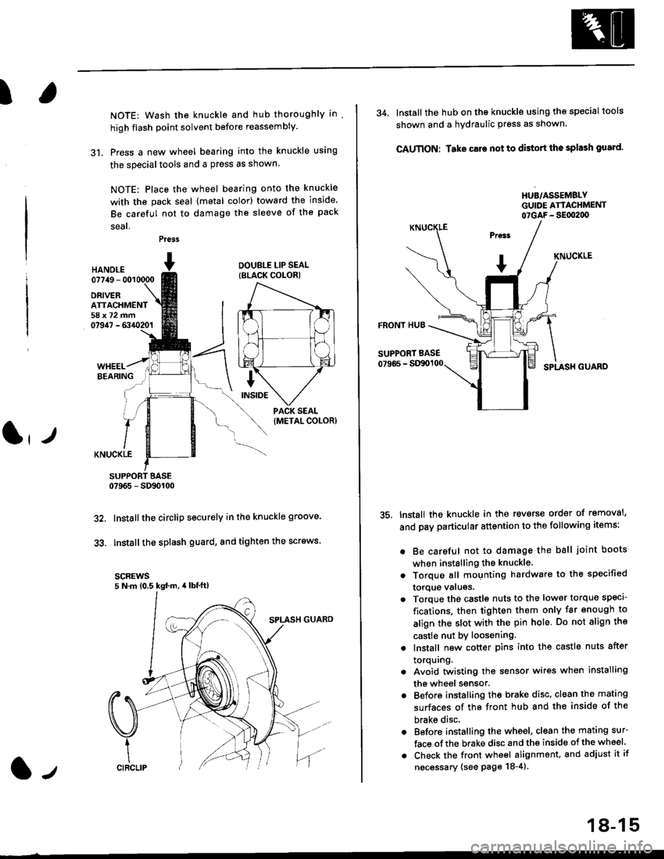
31. Press a new wheel bearing into the knuckle using
the specialtools and a press as shown
NOTE: Place the wheel bearing onto the knuckle
with the pack seal (metal color) toward the inside
Be careful not to damage the sleeve of the pack
seal.
Press
HANOI.E07749 - 001
DRIVERATTACHMENT58x72mm07947 - 6340201
DOUBLE LIP SEAL
{BLACK COLOR)
KNUCKLE
SUPPORT BASE07965 - SD90100
Installthe circlip securely in the knuckle groove'
Installthe splash guard, and tighten the screws.
scREws5 N.m (0.5 kgd m, 4lbt'ft)
32.
33.
l-,
18-15
34. lnstall the hub on the knuckle using the specialtools
shown and a hydraulic press as shown.
CAUTION: Take care not to distort tho splash gusrd'
HUB/ASSEMBLYGUIDE ATTACHMENT07GAF- SEflt2d)
KNUCKLE
FRONT HUB
SUPPORT BASE
07966 - StXx)100SPLASH GUARD
tnstall the knuckle in the reverse order of removal'
and pay particular attention to the following items:
. Be careful not to damage the ball joint boots
when installing the knuckle.
. Torque all mounting hardware to the specified
torque valugs.
. Torque the castls nuts to the low€r torque specl-
fications, then tighten them only far enough to
align the slot with the pin hole. Do not align the
castle nut by loosening.
. lnstall new cotter pins into the castle nuts after
torquing.
. Avoid twistin0 the sensor wires when installing
the wheel ssnsor.
. Before installing the brake disc, clean the mating
surfaces of the front hub and the inside of the
brake disc.
. Before installing the wheel, clean the mating sur-
face ofthe brake disc and the inside of the wheel
. Check the front wheel alignment, and adjust it if
necessary (see page 18-4).
Page 1140 of 2189
Front Suspension
L
Lower Ball Joint Replacement
Remove the knuckle (see page 18-11).
Remove the boot by prying the set ring off.
Check the boot for deterioration and damage.
replace if necessary.
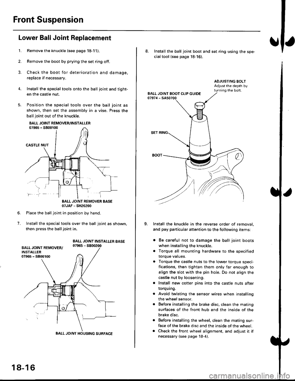
Install the special tools onto the ball joint and tight-
en the casfle nut.
Position the special tools over
shown. then set the assembly in
ball joint out of the knuckle,
BALL JOINT REMOVER/INSTALLER07965 - SB00r00
CASTLE NUT
the ball joint as
a vise. Press the
lf
7.
BALL JOINT REMOVER BASE07JAF - SH20200
Place the ball joint in position by hand.
Install the special tools over the ball joint as shown,
then press the ball joint in.
BALL JOINT INSTALLEB BASE07965 - 5800200
BALL JOINT HOUSING SURFACE
18-16
8. Install the ball joint boot and set ring using the spe-
cial tool (see page 18-16).
ADJUSTING BOLTAdjust rhe depth byturning the bolt.
Install the knuckle in the reverse order of removal,
and pay particular attention to the following items:
. Be careful not to damage the ball joint boots
when installing the knuckle,
. Torque all mounting hardware to the specified
torque values.
. Torque the castle nuts to the lower torque speci-
fications. then tighten them only far enough to
align the slot with the pin hole. Do not align the
castle nut by loosening.
. Install new cotter pins into the castle nuts after
torquang.
. Avoid twisting the sensor wires when installing
the wheel sensor.
. Before installing the brake disc. clean the mating
surfaces of the front hub and the inside of the
brake disc.
. Before installing the wheel, clean the mating sur-
face of the brake disc and the inside of the wheel.. Check the front wheel alignment, and adjust it if
necessary {see page 18-4).
Page 1153 of 2189
Rear Damper
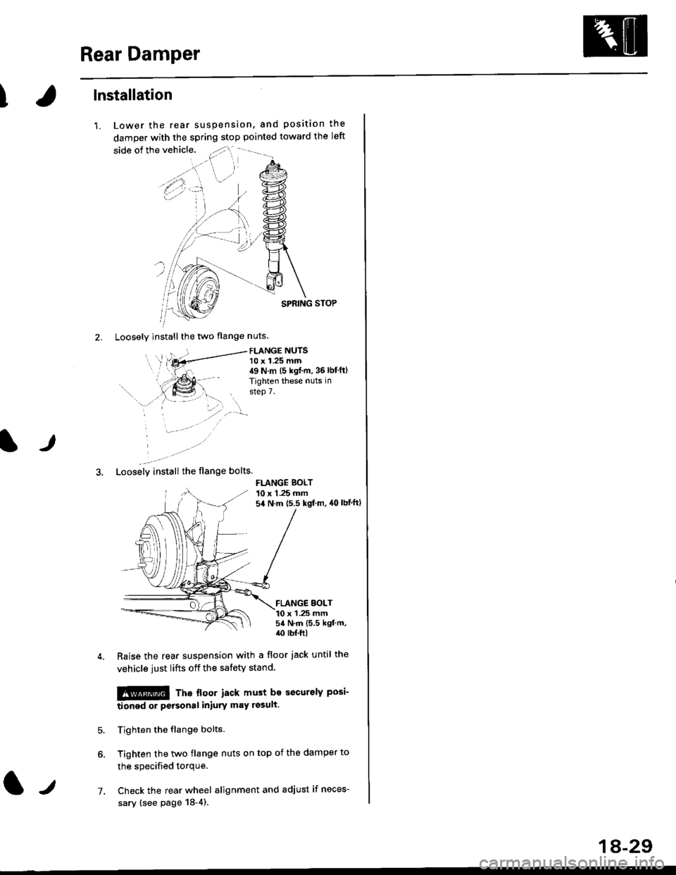
Ilnstallation
'1. Lower the rear suspension, and position the
damper with the spring stop pointed toward the left
SPRING STOP
2. Loosely installthe two flange nuts
FLANGE NUTS10 x 1.25 mm49 N.m (5 kgf.m, 36 lbt'ft)
Tighten these nuts in
step 7.
lr
3. Loosely install the flange bolts.
FLANGE BOLT10 x 1.25 mm54 N.m {5.5 kgf m, 40 lbt'ft1
FLANGE BOLT10 x 1 .25 mm54 N.m {5.5 kgf.m,/r0 lb{.ft|
7.
Raise the rear suspension with a floor jack until the
vehicle just lifts off the safety stand.
!@@ Tne floor iacx must be securelY Posi-
tionod or peFonal iniury may rssull
Tighten the flange bolts.
Tighten the two flange nuts on top of the damper to
the specified torque.
Check the rear wheel alignment and adjust if neces-
sary (see page 18-4).
1A-29
Page 1750 of 2189
Precautions/Procedu res
Steering-related Precautions
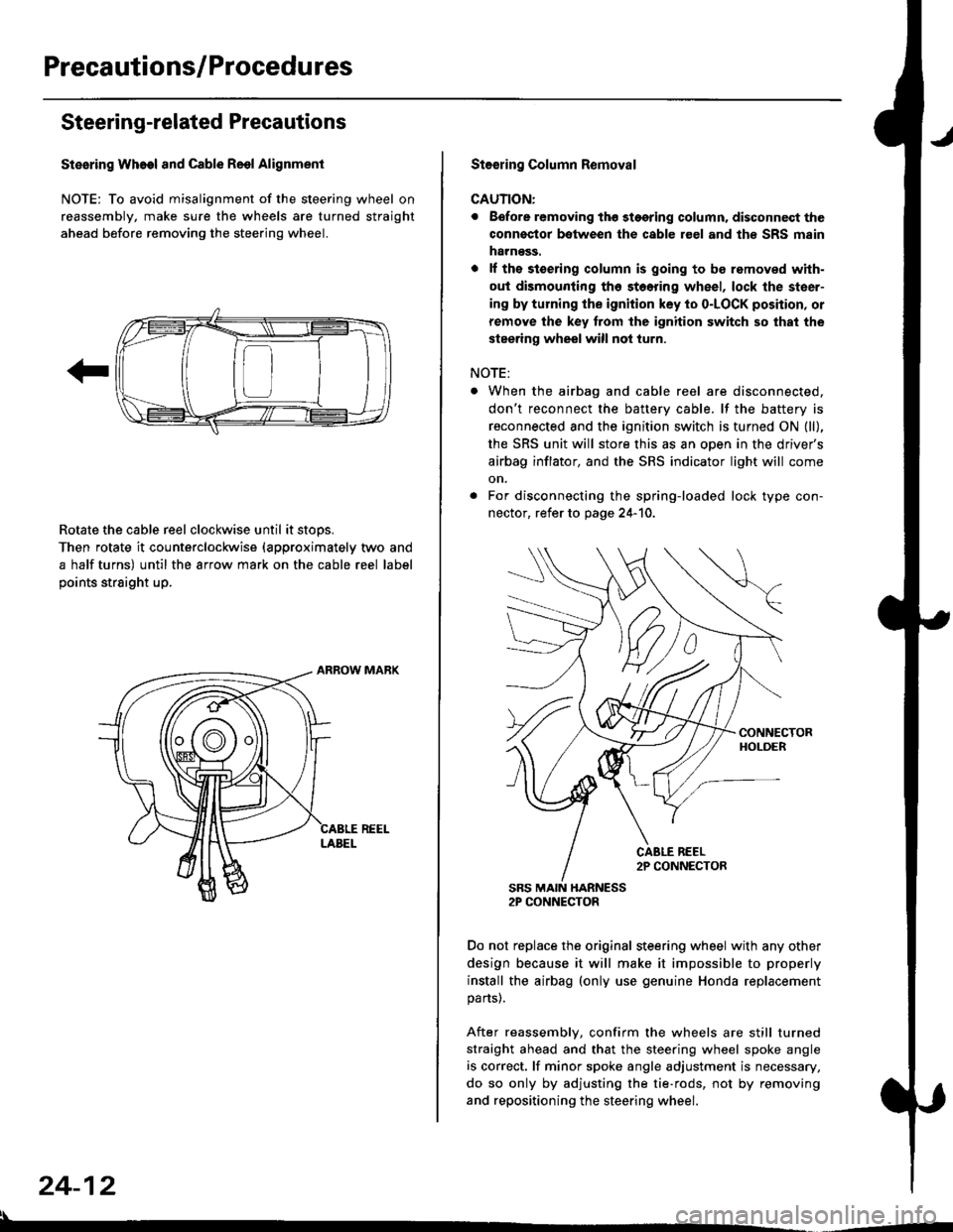
Stesring Wheel and Cable Reol Alignment
NOTE: To avoid misalignment of the steering wheel on
reassembly, make sure the wheels are turned straight
ahead before removing the steering wheel.
Rotate the cable reel clockwise until it stops.
Then rotate it counterclockwise {approximately two and
a half turns) until the arrow mark on the cable reel label
points straight up.
24-12
:l
St€€rin9 Column Removal
CAUTION:
. Eefore removing thg stggring column. disconnect the
connsstor bqtween the cable r€el and th€ SRS msin
harness.
. lf the stoering column is going to be romoved with-
out dismounting th6 stoering wheel, lock the steer-
ing by turning the ignition key to o-LOCK position, or
remove the key trom the ignition switch so that the
steering wheel will not turn.
NOTE:
When the airbag and cable reel are disconnected,
don't reconnect the battery cable. lf the battery is
reconnected and the ignition switch is turned ON (ll),
the SRS unit will store this as an open in the driver's
airbag inflator, and the SRS indicator light will come
on.
For disconnecting the spring-loaded lock type con-
nector, refer to page 24-'10.
SRS MAIN HARNESS2P CONNECTOR
Do not replace the original steering wheel with any other
design because it will make it impossible to properly
install the airbag (only use genuine Honda replacement
parts).
After reassembly, confirm the wheels are still turned
straight ahead and that the steering wheel spoke angle
is correct. lf minor spoke angle adjustment is necessary,
do so only by adjusting the tie-rods, not by removing
and repositioning the steering wheel.