1999 HONDA CIVIC heater
[x] Cancel search: heaterPage 373 of 2189

PGM-FI System
System Description
CKP/TDC/CYP Sensor
MAP Sensor
IAT SensorTP SensorEGR Valve Lift Sensor*'Primary H02SSecondary HO2SVSSBARO SensorELD*'KS€Starter SignalALT FR SignalAir Conditioning SignalA/T Gear Position SignalBattery Voltage {lGN.1}Erake Switch SignalPSP Switch SignalFuel Tank Pressure Sensor*iVTEC Pressure Switch*5Clutch Switch Signal*6Countershaft Speed SensornBMainshaft Speed Sensorrs
-\
----t /
F;ilrr j"-----fi-tri-'r.;l
Fb"t."'i" d" c;;il
F,h"'c;;tr*".io";-l
@."r.l"sc;;ll
EaM/PcM B""k-p F"""till
r\
-:/
Fuel IniectorsPGM-Fl Main Belay {Fuel Pump)MILIAC Valve!y'C Compressor Clutch RelayRadiator Fan Relay*,Condenser Fan RelayALT*'lcMEVAP Purge Control Solenoid
Primary HO2S HeaterSecondary H02S HeaterEGR Control Solenoid Valve*rEGR valve*6EVAP Bypass Solenoid Valve*'EVAP Control Canister Vent Shut
VTEC Solenoid Valve*5DLCLock-up Control Solenoid Valve*aShift Control Solenoid Valve*3Linear Solenoid Valve*3
*1: Dl6Y5 engine*2: USA model*3: CW (D16Y5 ensine), D16Y8 engine and 81642 ensine*4: '96 D16Y8 engine lcoupe),'97 Dl6Y7 engine (coupe: KL model, sedan: KL (LX) model),'97 D16Y8 engine {coupe: all models, sedan: KLmodel),'98-all models,'99'all models,'00-all models+5: D16Y5, D16Y8,816A2 engine*6: M/T (D16Y5 enginei*7: CVT 1D'l6Y5 engine)+8: A/T (D16Y7, D16Y8 engine)*9: '96 D16Y5 engine,'96 D16Y7 engine,'96 Dl6Y8 engine (sedan),'97 D16Y5 engine,'97 Dl6Y7 engine (coupe: KA, KC models, sedan:KA, KC, KL (LX) models, hatchback: all models),'97 D16Y8 engine (sedan: KA, KC modelsi
PGM-FI Sy3lem
The PGM-Fl system on this model is a sequential multipon fuel injection system.
Fuel iniector Timing and Duration
The ECM/PCM contains memories for the basic discharge durations at various engine speeds and manifold air flow rates.
The basic discharge duration, after being read out from the memory. is further modified by signals sent from various sen-
sors to obtain the final discharge duration.
ldle Air Control
ldle Air Control Valve llAC Valve)
When the engine is cold. the A,/C compressor is on, the transmission is in gear, the brake pedal is depressed, the P/S load
is high, or the alternator is charging, the ECM/PCM controls current to the IAC Valve to maintain the correct idle speed.
lgnition Timing Control
. The ECM/PCM contains memories for basic ignition timing at various engine speeds and manifold air flow rates.
lgnition timing is also adjusted for engine coolant temperature.
. Aknockcontrol system was adopted which sets the ideal ignition timing for the octane rating ofthegasoline used.*3
Othgr Control Funqtions
1. Starting Control
When the engine is started, the ECM/PCM provides a rich mixture by increasing fuel injector duration.
2. Fuel Pump Control
. When the ignition switch is initially turned on, the ECM/PCM supplies ground to the PGM-Fl main relay that sup-plies current to the fuel pump for two seconds to pressurize the fuel system.. When the engine is running, the ECI\4PCM supplies ground to the PGM-FI majn relay that supplies current to the fuel
oumo.
. When the engine is not running and the ignition is on, the ECM/PCM cuts ground to the PGM-FI main relay which
cuts current to the fuel pump.
11-104
INPUTS
ENGINE CONTROL MODULE (ECMY
POWERTRAIN CONTROL MODULE (PCM) OUTPUTS
Page 408 of 2189
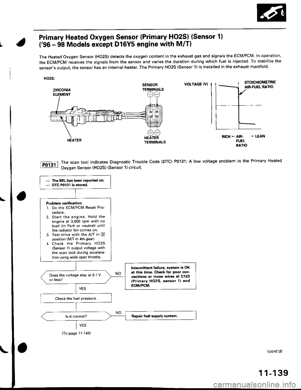
Primary Heated Oxygen Sensor {Primary HO2SI (Sensor 1)
t('96 - 98 Models except Dl6Y5 engine with M/Tl
The Heated Oxygen Sensor (HO2S) detects the oxygen content in the exhaust gas and signals the ECM/PCM. In operation,
the ECM/PCM receives the sjgnals from the sensor and varies the duration during which fuel is injected To stabilize the
sensor,s output, the sensor has an internal heater. The Primary HO2S (Sensor 1) is installed in the exhaust manifold.
HO2S:
VOLTAGE {VI
The scan tool indicates Diagnostic Trouble Code (DTC) P0131; A low voltage
Oxygen Sensor (H02S) (Sensor 1) circuit.
R|cH-AIR- - LEANFUELRANO
problem in the Primary Heated
SENSOR
ztRcoNlA
The MIL has be€n teported on.DTC P0131 is siorcd.
Problom verificalion:1. Do the ECM/PCM Reset Pro'
cedure.2. Start the engine. Hold theengine at 3,000 rpm with noload (in Park or neutral) untilthe radiator fan comes on,3. Test-drive with the A/T in Eposition (M/T in 4th gear)
4. Check the Primary HO2S(Sensor 1) output voltage with
the scan tool during accelera-
tion using wide open throttle.
lntcrmift€nt failura, 3Y3tem is OKat this tims. Check for Poor con-nections or loo3e wi.o3 at C123(Primlry HO2S, 3sn3or 1) and
ECM/PCM,
(To page 1I-140)
{cont'd)
1 1-139
Page 410 of 2189
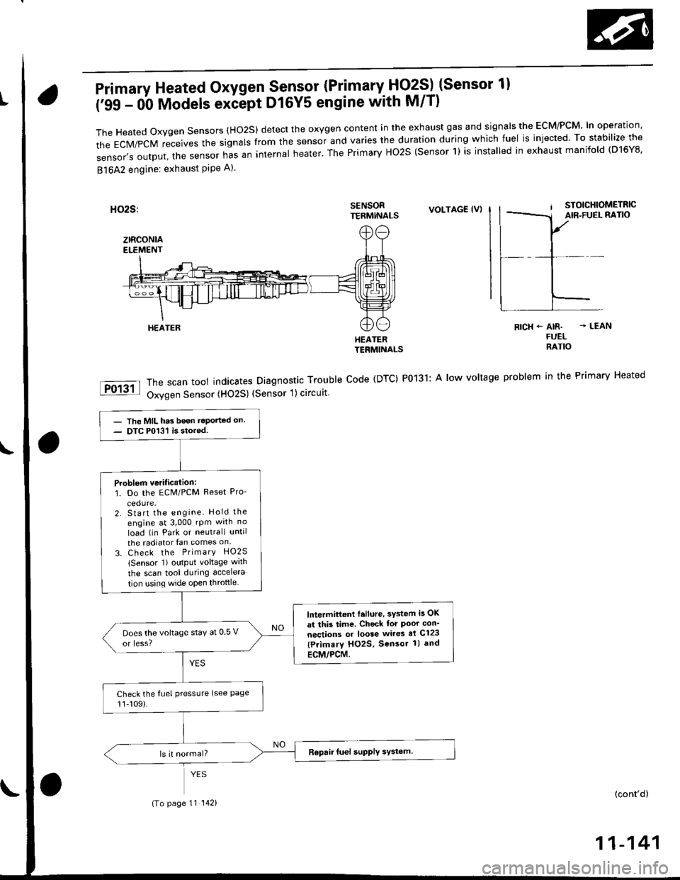
Primary Heated Oxygen Sensor (Primary- Fjq?S) (Sensor 1l
('99 - 0b Models exiept D16Y5 engine with M/T)
TheHeatedoxygensensors(Ho2S)detecttheoxygencontentintheexhaustgasandsigna|stheEcM/PcM'|noperation,
the EcM/pcM receives the signars from the sensor and varies the duration during which fuel is injected. To stabilize the
sensor,soutput,thesensornasaninternaIheater.ThePrimaryHo2S(sensorl)isinsta|ledinexhaustmanifo|d(D16Y8.
81642 engine: exhaust PiPe A)
SENSORTERMINALSVOLTAG€ (VI
HEATERTERMINALS
The scan tool indicates Diagnostic Trouble Code (DTC) P0131: A low voltage
Oxygen Sensor (HO2S) (Sensor 1) circuit
RICH+ AIR- - LEANFUELRATIO
problem in the Primary Heated
HEATER
- The MIL has been t€Ported on.- DTC P013'l is stored.
Problem veritication:1. Do the ECM/PCM Reset Pro-
2. Start the engine. Hold the
engine at 3,000 rpm wrth no
load (in Park or neutral) until
the radiator fan comes on
3. Check the PrimarY HO2S
lSensor 1) output voltage wath
the scan tool during accelera
tion using wide open throttle
lntermittont f.ilure, 3ystem i3 OK
at thi3 time. Check tor Poor con'
nections or loose wires el C123
{Primary HO2S, Sensor 1) and
ECM/PCM.
Does the voltage stay at 0 5 v
or less?
Check the fuel pressLlre (see Page11,109).
(To page 11 142)(cont'd)
11-141
Page 414 of 2189
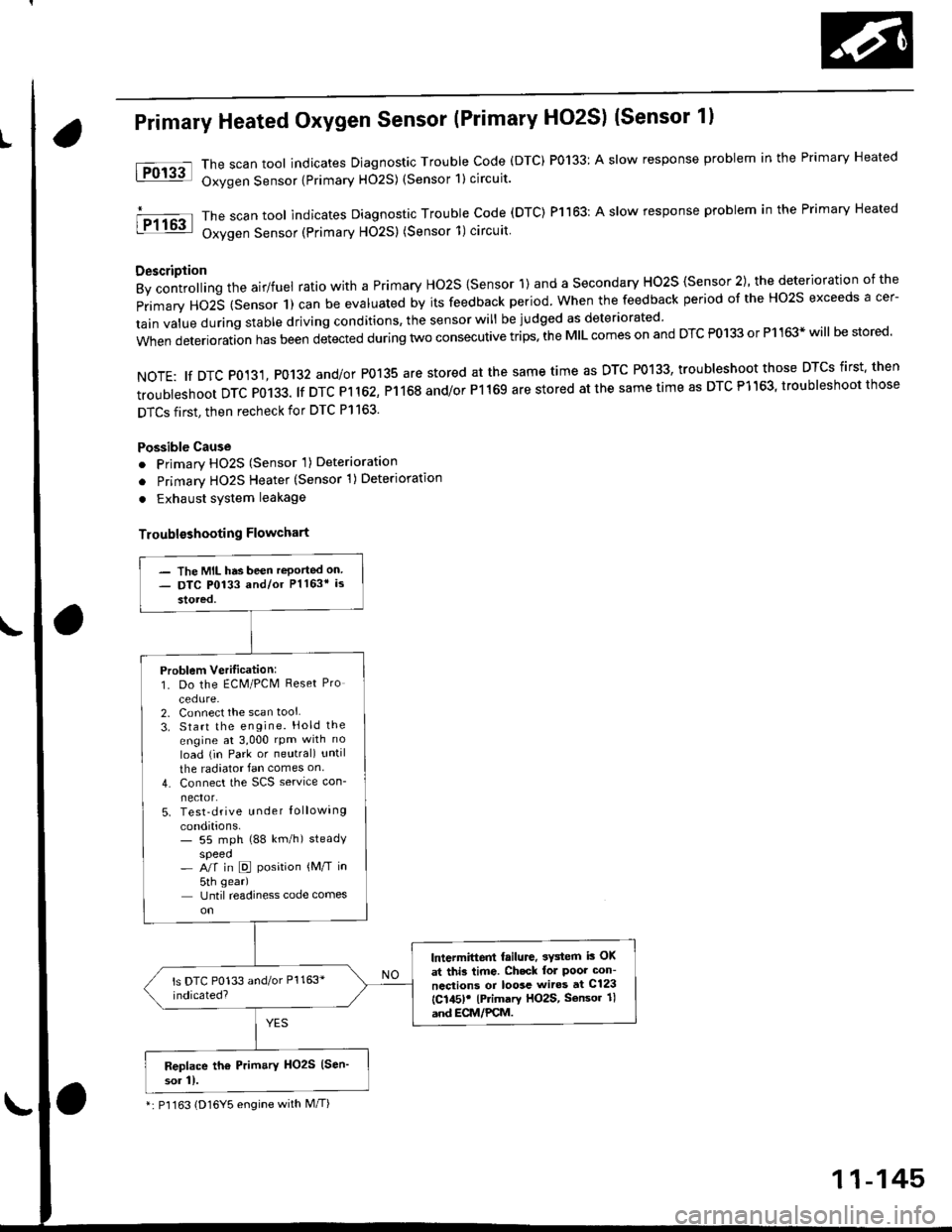
Primary Heated Oxygen Sensor (Primary HO2S) (Sensor 1l
The scan tool indicates Diagnostic Trouble Code (DTC) P0133: A slow response problem in the Primary Heated
Oxygen Sensor {Primary H02S) (Sensor 1) circuit.
The scan tool indicates Diagnostic Trouble code (DTC) Pl163: A slow response problem in the Primary Heated
Oxygen Sensor (Primary HO2S) (Sensor 1)circuit
Description
By controlling the airlfuel ratio with a Primary Ho2S {Sensor 1) and a secondary HO2S {Sensor 2), the deterioration of the
primary HO2S (Sensor 1) can be evaluated by its feedback period. when the feedback period of the Ho2s exceeds a cer-
tain value during stable driving conditions, the sensor will be judged as deteriorated
when deterioration has been detected during two consecutive trips. the MIL comes on and DTC P0133 or P1163* will be stored'
NOTE: tf DTC P0131, P0132 and/or P0135 are stored at the same time as DTC P0133, troubleshoot those DTCS first' then
troubleshoot DTC P0133. lf DTC Pl 162, P1168 and/or P1169 are stored at the same time as DTC P1163, troubleshoot those
DTCS first, then recheck for DTC Pl163.
Possible Cause
o Primary HO2S (Sensor 'l) Deterioration
o Primary HO2S Heater (Sensor 1)Deterioration
. Exhaust system leakage
Troublsshooting Flowchart
tFol3al
I P1163
- The MIL has been reported on- DTC P0133 and/or Pl163* is
stored,
Problem Verilication:1. Do the ECM/PCM Reset Pro
cedure-2. Connect the scan tool
3. Start the engine. Hold the
engine at 3,000 rpm with no
load (in Park or neutral) until
the radiator fan comes on
4. Connect the SCS service con-
nector.5. Test-drive u nder Iollowing
conditions.- 55 mph (88 km/h) steadyspeed- A/f in D position {M/T in
5th gear)
Until readiness code comes
lntermittent failure, 3Y3tem i3 OK
at thi3 time. Ch.ck lol Poor con-
ncctions or loosc wiros at C123
{C145)! lPrimary HO2S, Sensor 1l
and ECM/PCM.
Replace th6 Prim.ry HO2S (Sen'
sor 11.
*: P'l163 (D16Y5 engine with M/T)
11-145
Page 426 of 2189
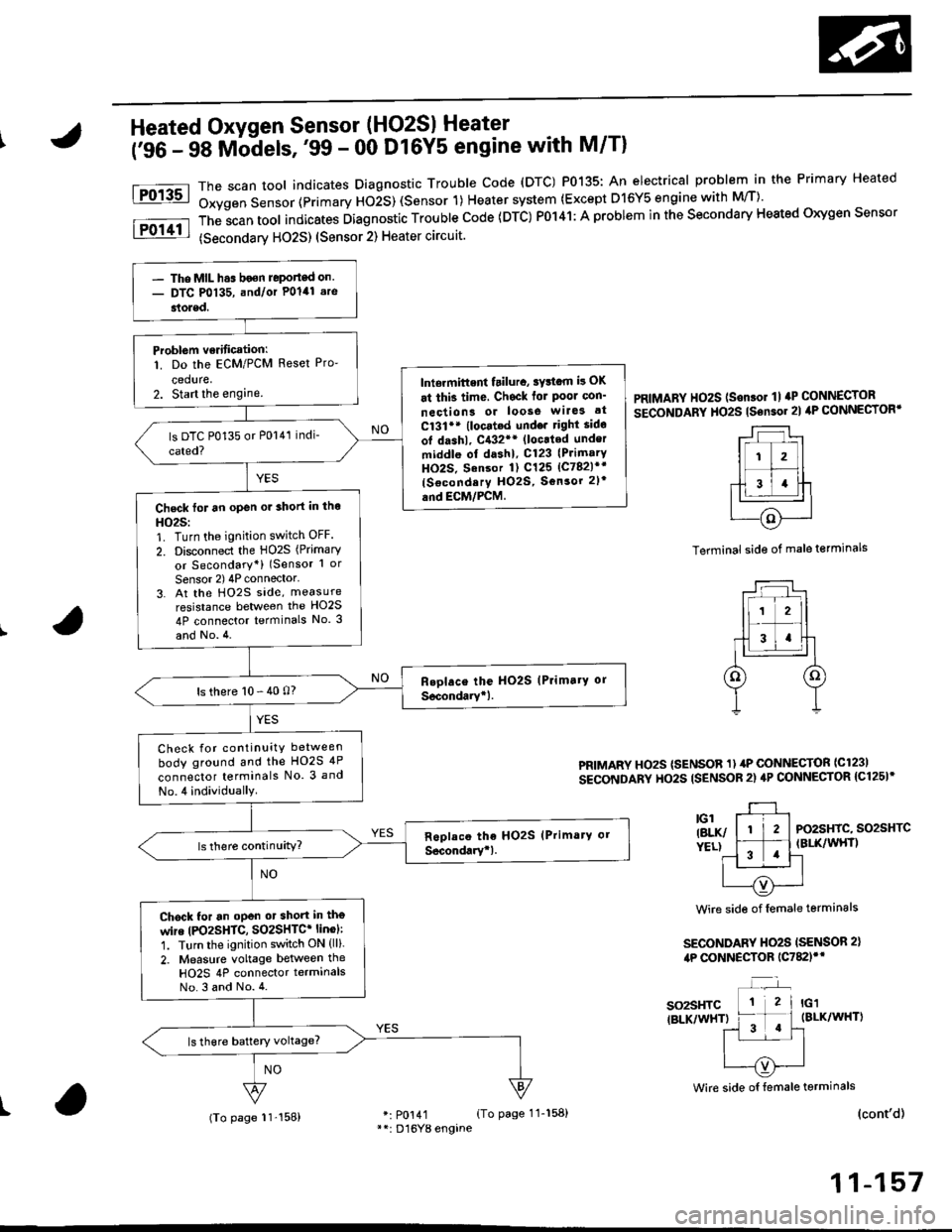
tFo135l
iPol4tl
Heated Oxygen Sensor (HO2SI Heater
('96 - 98 Mbdels,'99 - 00 Dl6Y5 engine with M/Tl
*: p0141 (To page 11-158)**: D'16Y8 engane
The scan tool indicates Diagnostrc Trouble code (DTC) P0135: An electrical probl€m in the Primary Heated
Oxygen Sensor (Primary HOiS) (Sensor 1) Heater system (Except D16Y5 engine with M/T)'
The;can tool indicates Diagnostic Trouble code (DTC) P0141: A problem in the secondary Heated oxygen sensor
(secondarv HO2S) (Sensor 2) Heater circuit.
PRIMARY HO2S (Son.or 1l aP CONNECTOR
SECoNDARY HO2S tsensor 2l ilP CONNECTORT
Terminal side of male terminals
PRIMARY HOzS (SENSOR 1) 4P CONNECTOR ICl23I
SECONDARY HO2S ISENSOR 2) 4P CONNECTOR {C125I*
PO2SHIC, SO2SHTCIBLK/WHT)
Wire side of female terminals
SECONDARY HO2S ISENSOR 2),tP CONNECTOR 1C782)'*
so2sHTC{BLK/WHT)
Wire side oI female terminals
I(cont'd)
11-157
- The MIL h.s boen Jeponed on.- DTC P0135, and/or Polal .re
stoled.
Problem verificationl
1. Do the ECM/PCM Reset Pro-
ceduae,2. Start the enginelniermittent tailura, sYttam i! OK
at thi3 time, Chsck for Poor con'
neciion3 or loose wilG3 at
C131** (locat.d undo. right sido
ot dashl, C{32** (loc.ted under
middle ol dashl, C123 (PrimarY
HO2S. Sansor 1) C125 lc782l*r
{Socondery H02S, Sonsor 2l'
and EcM/PcM.Check for an open or 3hort in tho
HO25:1. Turn the ignition switch OFF.
2. Disconnect the HO2S (Primary
or Secondary*) (Sensor 1 or
Sensor 2) 4P connector'3. At the Ho2s side, measure
resistance between the HO2S
4P connector terminals No. 3
and No.4.
ls there 10 - 40 0?
Check for continuity between
body ground and the HO2S 4P
connector terminals No. 3 and
No.4 individually
Chock for an oPen ot short in tho
wire |PO2SHTC, SO2SHTC* linol:
1. Turn the ignition switch ON (ll).
2. Measure voltage between the
HO2S 4P connector terminalsNo.3 and No.4.
(To page 11'158)
Page 427 of 2189

PGM-FI System
a
a
Heated Oxygen Sensor (HO2S) Heater
('96 - 98 Models,'99 - 00 D16Y5 engine with M/T) (cont'dl
PRIMARY HO2S {SENSOR 1I 4P CONNECTOR{c1231SECONDARY HO2S {SENSOR 2} 4PcoNNECTOR 1C125)r
r-l --'1
ll i2l
f;T;ttcl|BLK/ &)YELI Y
Wire side of fomale lerminals
SECONDARY HO2SISENSOR 2) 4P CONNECTOR{c78ilf
IBLK/WHT)
Wire side of lemale terminals
(From page 11-157)
Wire sid€ ot temale terminals
SO2HTC(BLK/WHTI* PO2SHTC{BLK/WHTI
*: P0141*+: Dl6Y8 engine
11-158
(From page 11-157)
Check tor an op6n or 3hoft in thewire {lGl lin6):Measure voltage between theHO2S 4P connector terminals No.3(D16Y8 engine: No. 4) and bodyground.- Repair open or shon in thewire between Primary HO2Slson.or 1), {No. 15 ALTERNA-TOR SP SENSORI (7.5 Al fuseand Secondary HO2S, Sonsol2t,.- Replace the No. 15 ALTERNA-TOR SP SENSOR 17.5 A) tuse.Check for an open in the wireIPO2SHTC, SO2SHTC' linel:1. Turn the ignition switch OFF.2. Reconnect the HO2S 4P con-nector.3. Disconnect the ECM/PCM con-nector A (32P).
4. Turn the ignition switch ON (ll).
5. Measure voltage between theECM,/PCM connector terminals46 and 410 {A5 and A10)*.
Ropail opan in the wire b€twoenECM/PCM lA6, A5l* and HO2S{Primary, Secondary+1.
ls there 0.1 V or less?
Substitute a known-good ECM/PCM and recheck. ll symptom/indication goes awry, repbcetho origin.l ECM/PCM.
ECM/PCM CONNECTOR A I32P)
so2sHrc ItBLK/WH0.J
pozsxtc E/
IBI-K/WHTI ^,-----{v}-|.=,|I
PG1IBLK}3u I JsTgT roll12r3t5t6Ittar920z2l 2321
25272A2i3o
Check tor a short in the wire{PO2SHTC. SO2SHTC* line):'1. Turn the ignition switch OFF.2. Disconnect the ECM/PCM con-nector A (32P1.
3. Check for continuity betweenthe ECM/PCM connector termi-nal 46 (A5)* and body ground.
Repair short in thg wire betwe€nECM/PCM lA6, A5*l .nd HO2S(P.im.ry, Socondary*).
Substitute a known-good ECM/PCM and recheck. It symptom/indicetion goes away, rophcethe original ECM/PCM.
Page 428 of 2189
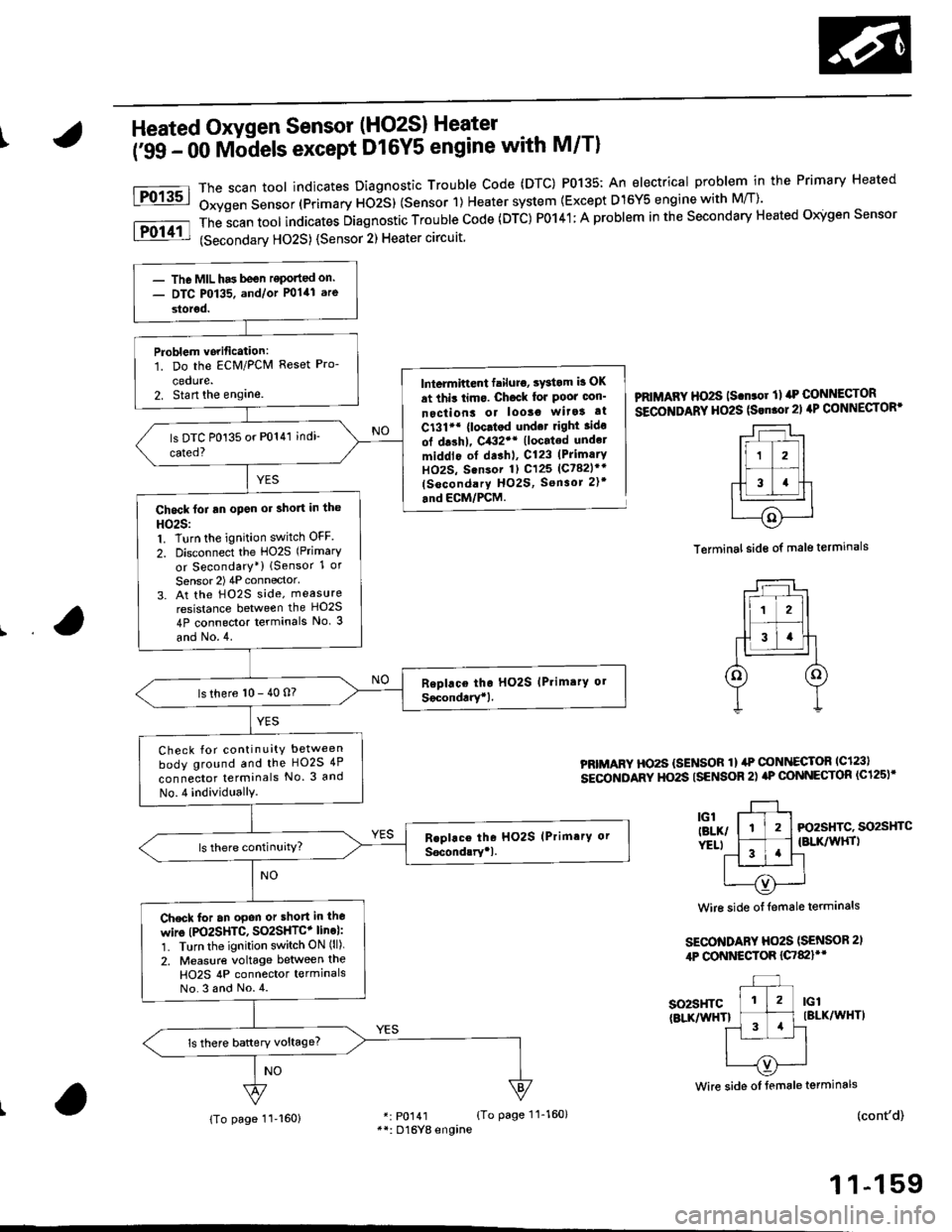
IHeated Oxygen Sensor (HO2S) Heater
i'ss - oo Mb-dels except D16Y5 engine with M/Tl
The scan toot indicates Diagnostic Trouble Code (DTC) P0135: An electrical problem in the Primary Heated
Oxygen Sensor (Primary ttOiS) (Sensor 1) Heater system {Except D15Y5 engine with M/T)'
The
-scan tool indicates Diagnostic Trouble Code (DTC) P0141; A problem in the Secondary Heated Oigen Sensor
(Secondarv HO2S) {Sensor 2) Heater circuit
Fo13sl
Fol11l
lntermiftent failuro, sYstom b OK
at thit limo. Ch6ck lor Poor oon'
nectiont or looso wita! at
C131'* {loc.tod und.t right ido
ol drshl, C432'* (located undel
middlo of dashl, C123 (PrimarY
HOzS, Sensor 1) C125 (Ct82lr'
(socondary HO2S, Sensor 2)t
.nd ECM/PCM.
PRIMAFY HO2S ls.n.or ll rrP CONNECTOR
SECOITIDARY HO2S (Srn.ol21 4P CONNECTOR'
Terminal side of male terminals
PRIMARY HO2S {SENSOR 1} ilP @NI{ECTOR lc123l
sEcoNDARY HO2S ISENSOR 2) aP @NNECTOR (C125)'
3l-, l-tl-t Fo2sHrc. so2sHrc
ver.t l ^-1 .'l {BLK/wHrl
11 '!'l-l
| --=- Iu----{v)'---..-'
Wire side of {emale terminals
SECO'TIDARY Ho2S (SENSOR 2,
4P CONNESTOR {C7&llt'
so2sHTc(BLKnflHTlIBLK/WHT)
(cont'd)
1 1-159
Wire side oI female terminals
r: p0141 {To page 11-160}**: D16Yg engine
- The MIL has been reponed on.- DTC P0135. and/or P0141 are
storod.
Problem vorification:1. Do the ECM/PCM Reset Pro-
cedute.2. Stan the englne.
Chock foi an open or short in the
HO25:1. Turn the ignition switch OFF
2. Disconnect the HO2S (Primary
or Secondary*) lSensor 1 or
Sensor 2) 4P connector'
3. At the H02S side, measure
resistance between the HO2S
4P connector terminals No. 3
and No.4.
ls there 10 - 40 n?
Check for continuity between
body ground and the HO2S 4P
connector terminals No. 3 and
No.4 individuallY.
Check for an opon or short in lho
wire (PO2SHTC, SO2SHTC+ line):'1. Turn the ignition switch ON (ll).
2. Measure voltage between the
H02S 4P connector termlnalsNo.3 and No.4.
{To page 11-160}
Page 429 of 2189

PGM-FI System
Heated Oxygen Sensor (HO2S) Heater
('99 - 00 Models except D16Y5 engine with M/T)
(From page 11-159)
Substitute a known-good ECM/PCM and recheck. lf symptom/indication goes away, replacethe origin.l ECM/PCM.
(cont'dl
PRIMARY HO2S ISENSOR 1I 4P CONNECTOB{c123)SECONDANY HO2S ISENSOR 2} 4PcoNNECTOR (C125)*
-r--r ,
lr zl
-f-13 4llc'l L--r-J-r
relxr p1YELI Y
Wire side of temale terminals
SECONDARY HO2S(SENSOR 21 4P CONNECTOR{c782}rr
IG1 IBLK/WHT)
NO
Wire side of female telminals
ECM/PCM CONNECTORS
Wire side of female terminals
ECM/FCM CONNECTORS
*: P0141**: Dl6Y8 engine
1 1-1 60
Check for an open in the wires{lGl* line}iMeasure voltage between the primary HO2S 4P connector terminalNo. 3 (D16Y8 engine: No. 4) andbody ground.- Repeir open or shon in thewire between Primary HO2Slsensor 1), {No. 15 ALTERNA-TOR SP SENSOR) (7.5 A) fus€and Secondary HO2S, Sensor2t,.- ReDlace the No. 15 ALTERNA-TOR SP SENSOR {7.5 A tuse.
ls there battery voltage?
Check ,or an open in the wires(PO2SHTC, SO2SHTC' linel:1. Turn the ignition switch OFF.2. Reconnect the HO2S 4P con-nector,3. Disconnect the ECN4/PCM connector C (31Pi (ECM/PCM con-nector A (32P))i.
4. Turn the ignition switch ON (lli.
5. Measure voltage between theECM/PCM connector terminals82 and Cl 182 and AB)*.
Reprir open in the wirc betwo€nECM/PCM (Cl, A8i) and HO2S(Primary, Secondary+).
ls there 0.1 V or less?
(From page 11 l59i
Check tor a short in the wiresIPO2SHTC, SO2SHTC* linel:1. Turn the ignition switch OFF.2. Disconnect the ECM/PCM con-nector C (31Pi (ECM/PCM connector A (32P)i*.
3. Check tor continuity betweenthe ECM/PCM connector terminal C1 {A8)* and body ground.
Repai. short in the wire b€tweenECM/PCM lcl, A8.l and HO2S(Pdmery, Secondary*1.
Substitute a known-good ECM/PCM end recheck. lf symptom/indication goes away, replacethe o.iginal ECM/PCM.
Wire side of female terminals