1999 HONDA CIVIC brake fluid
[x] Cancel search: brake fluidPage 977 of 2189

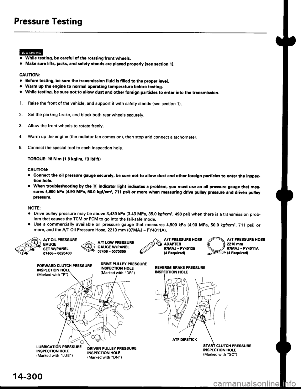
Pressure Testing
. While testing, be careful of the rot8ling front wheels.
. M8k6 suro lifts, iacks, and satety stands are placed properly lsee section 11.
CAUTION:
. Before testing, be sur. the transmb3ion fluid is fillod to the propor lcvel.. Warm up the engin€ to nolmal operating tsmperature bofore testing. While t€sting, be 3ure not to allow dust and other loreign particles to onler into the transmi$ion.
1. Raise the front of the vehicle, and support it with safety stands (see section 1).
2. Set the parking brake. and block both rear wheels securely.
3. Allow the front wheels to rotate freely.
4. Warm up the engine (the radiator fan comes on), then stop arid connect a tachometer.
5. Connect the special tool to each inspection hole.
TOROUE: 18 N.m (1.8 kgt'm, 13 tbtfr)
GAUTION:
. Connect the oil pressuro gauge !!€curoly, bs sur6 not to allow dust and other foroign particlG3 to ontar the inspsc-tion hole.
. Whon troubleshooting by tho E indicltor light indic.t6 a problam. you mu3t u3e an oil p.essure gluge that moa,sures 4,9(X) kPa (a.90 MPa,50.0 kS cr*,771psi) or more when molsuring driv. pulley pressure and driven pullcypre33ure.
NOTE:
. D.ive pulley pressure may be above 3,430 kPa (3.i8 MPa,35.0 kgf/cmr, 498 psi) wh€n there is a transmission prob-
lem that causes the TCM or PCM to go into the fail-safe mode,. Use a commercially available oil pressure gauge that measures 4,900 kPa {4.90 MPa, 5O.O kgf/cmr, 711 psi) ormore, and the Ay'T Oil Pressure Hose, 2210 mm (07MAJ - PY4011A).
FORWARD CLUTCH PRESSUREINSPECTION
lMarked with "F")
REVERSE BRAKE PRESSUREINSPECTION I.IOLE
A/T OIL PRESSUREGAUGESET W/PANEL0ta{r6 - oO2Oi|(Xt
A/T LOW PRESSUREGAUGE W/PANEL0706 - qt7o:t{ro
DRIVE PULLEY PRESSUREINSPECTION HOI.E(Marked with "DR")
A/T PRESSURE HOSEADAPTER07MAJ - PYar'120lil R.qulr.d)
A/T PRESSUBE HOSE2210 mm07MAJ - PYitollAla R.quir.d)
(
INSPECNON HOLE(Marked with "SC")
CLUICH PRESSURE
INSPECTION HOLE(Marked with "LUB")
DRIVEN PULLEY PRESSUREINSPECTION HOLElMarked with "DN")
14-300
ATF DIPSTICK
Page 978 of 2189

1.
Start the engine.
Shift to the respective shift lever positions in the table, and measure the following pressures at 1'500 rpm'
. Forward Clutch Pressure
. Reverse Brake Pressure
. Drive Pulley Pressure
. Driven Pulley Pressure
8. Shift to E posltion, and measure the lubrication pressure at 3,000 rpm'
Disconnect the special tool after pressure testlng
Install the sealing boits in the jnspection holes with new sealing washers, and tighten the bolts to the specified
toroue.
TOROUE: 18 N.m {1.8 kgf'm, 13 lbf'ft}
CAUTION: Keep all foreign particles out of the transmission'
9.
10.
PBESSURESHIFT LEVER
POSmONSYMP{OMPROBABLE CAUSE
FLUID PRESSURE
Standard/Ssrvice Limit
Forwa rd
Clutch
ENo or low for-
ward clutch
pressure
Forward Clutch1.4 - 1.75 MPa
(14.3 - 17.8 kgtcm'�, 203 - 253 Psi)
Reverse
Brake
tsNo or low
reverse brake
pressure
Reverse Brake1.4 - 1.75 MPa
(14.3 - '17.8 kg7cm'�, 203 - 253 Psi)
Drive
Pulley
NNo or low
drive pulley
pressure
ATF pump, PH reg-
ulator valve, PL
regulator valve,
Shift valve
0.2 - 0.7 MPa
(2 - 7.1 kgflcm'�, 28 - 101 Psi)
Drive pulley
pressure roo
high
PH regulator valve,
PL regulator valve,
Shift valve. Shift
control linear
solenoid
Driven
Pulley
No or low
driven pulley
pressure
ATF pump, PH reg-
ulator valve, Shift
valve, Shift control
linear solenoid
1.5 - 2.3 MPa
(15.3 - 23.5 kg?cm'�, 218 - 334 Psi)
Driven pulley
pressure too
h igh
PH regulator valve
LubricationNo or low
lubrication
pressure
ATF pump,
Lubrication valve
Above 0.2 MPa
(Above 2 kgf/cm'�. 30 Psi)
14-301
Page 979 of 2189

Lower Valve Body Assembly
Replacement
@ Make sure lifts, iacks, and saf€ty stands
are placsd prop€rly {sea section 1).
CAUTION: While removing and installing th6 lower
valve body asssmbly, b€ sule not to allow dust and
other for€ign particles to entsr inio the transmksion.
1. Raise the front of the vehicle, and support it with
safetv stands (see section 1).
2. Set the parking brake, and block both rear wheels
securetv.
4.
6.
Remove the drain plug, and drain the CVT fluid.
Reinstall the drain plug with a new sealing washer(see page 1+299).
CAUTION: Keop all of other toreign parliclos out of
the transmission.
Disconnect the 8P connector from the solenoid har-
ness connector.
Remove the ATF cooler hoses at the ATF cooler
lines. Turn the ends of the ATF cooler hoses up to
prevent ATF from flowing out, then plug the ATF
cooler noses.
CAUTION: Keep all of other foroign particlo3 out of
tho transmission.
Remove the right front mounvbracket.
10 x 1.25 mmila N.m (,1.5 kgf.m, 33 lbtft)
RIGHT FRONTMOUNT/BRACKET
ATF COOLER LINE
10 x 1.25 mmsil N.m 15.5 kgf.m,40 rbr.ft)
ATF COOLER HOSE
14-302
14.
7. Remove the ATF cooler outlet line.
8. Remove the ATF cooler line bracket bolt.
9. Remove the ATF pan (fourteen bolts).
10. Remove the ATF strainer (two bolts).
1 l. Remove the one bolt securing the solenoid harness
connector,
12. Remove the
bolts).
lower valve body assembly (eight
LINE BOLT28 N.m (2.9 kgtm,21 lbtft)SEALINGReplace.
ATF COOI.-EROUTLET
OOWEL PIN
O.RINGFeplace.
SOLENOIO HARNESSCONNECTOR
5x1.0mm12 N.m 11.2 kgt.m,8.7 tbt.ftlO.RINGReplace.ATFSTNAINER
6x1.0mm12 N.m 11.2 kgt m,E.7 tbt'ft)
OOWEL NN
BODY ASSEMBLY
6x1.0mm12 N.m 11.2 kgf.m,8.7 rbf.ft)
ATF PAN GASKETReplace.
VALVE
ATF COOLER INLETUNE BRACKET BOLT8 x 1,25 mm26 N.m {2.7 kgf.m,20 tbf.frl
13.
ATF PANx 1.0 mm12 N.m 11.2 kgf.m, E.7 lbf.ftl
Install the new lower valve bodv in the reverse
ordgr of the removal orocedure.
CAUTION: Koep all ot other fo.oign particles out of
ths transmission.
NOTE:
. Replace the following parts:
- O-rings on the solenoid harness connector
and the ATF strainer- ATF pan gasket- Sealing washers
. lf the ATF cooler inlet line bracket is bent or
warped, put it back to the original position.
Perform the start clutch calibration orocedure on
page 14-293.
Page 980 of 2189

ATF Filter
l.Removal/lnstallation
!@ Make sure lifts, lEcks, snd safoty stands
ara pl8ced properly {sae section 1).
CAUTION: While removing and installing the ATF tilier,
be sure not to allow dust or other for6ign particle3 to
enter thg transmission.
1. Raise the front of the vehicle, and support it with
safety stands (see section 1).
2. Set the parking brake, and block both rear wheels
securely.
3. Remove the drain plug, and drain the CVT fluid.
Reinstall the drain plug with a new sealing washer
{see page 14-299).
fl,
5.
CAUTION: Keep all toreign particles out ot the
transmission.
Remove the ATF cooler hoses at the ATF cooler
lines. Turn the ends of the ATF cooler hoses up to
prevent ATF from flowing out, then plug the ATF
cooler noses.
CAUTION: Keep all foreign particles out of the
transmission.
Remove the right front mounvbracket.
10 x 1.25 mm4{ N.m {i1.5 kgf.m,33 lbf ft)
ATF COOLER LINE
10 x 1.25 mm54 N.m {5.5 kgt'm,
40 rbl.ft)
ATF COOLER HOSE(|'t
14-303
6. Remove the ATF cooler outlet line.
7. Remove the ATF cooler line bracket bolt.
8. Remove the ATF pan (fourteen bolts)
9. Remove the ATF cooler inlet line from the ATF pan
(three bolts).
10. Remove the ATF filter, and clean it.
11. Check that the ATF filter is in good condition.
12. Replace the ATF filter if it is clogged.
LINE BOLT28 N.m {2.9 kgf.m,21 lbt.ft)
ATF COO1TR OUTIET
6x1.0mm
ATF COOLER INI-ETLINE ERACKET BOLT8 x 1.25 mm26 N.m (2.7 kgt.m,20 rbtftt
O.RINGReplace.
ATF
ATF FILTER
ATF PAN
6x1.0mm12 N.m (1.2 kgt'm,8.7 lbl'ft)
lnstall the ATF filter in the reverse order of the
removal procedure.
GAUTION: Keep all foreign particles out ot the
transmission,
NOTE:
Replace the O-rings, the ATF pan gasket and
sealing washers.
lf the ATF cooler inlet line bracket is bent or
warped. put it back to the original position
GASKETReplace.
'13.
12 N m (1.2 kgf m,
Page 1014 of 2189

Transmission
Reassembly
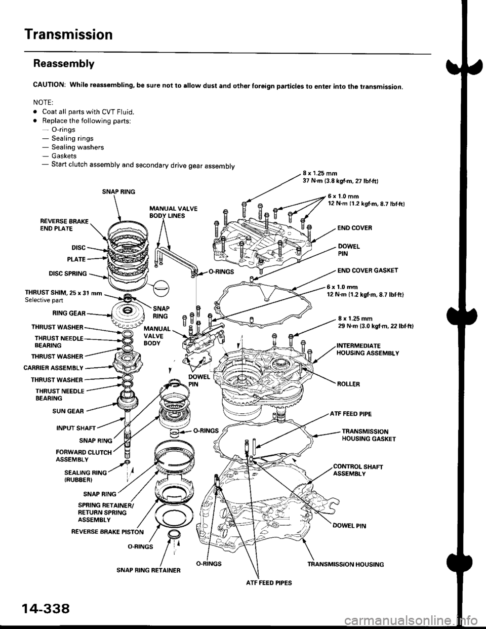
CAUTION: While reassembling. be sure not to sllow dust and othor foreign particles to enter into the transmission.
NOTE:
. Coat all parts with CVT Fluid.
. Replace the following parts:- O-rings- Sealing rings- Sealing washers- Gaskets- Start clutch assembly and secondary drive gear assembly8 x 1.25 mm37 N.m {3.8 kgf.m,27 lbtftl
MANUAL VALVE
6x1.0mm12 N m 11.2 kgf.m,8.7 lbl.ft)
LINESREVERSE BRAKEEND PLATE
Dtsc
PLATE
DISC SPRING
THRUST WASHER
CARRIER ASSEMBLY
THRUST WASHER
THRUST NEEDLEBEARING
END COVEB
DOWELPIN
END COVER GASKET
6x1.0mm12 N.m 11.2 kgtm,8.7 lbtft)THRUST SHIM,25 x 31 mmSelective part
RING GEAR
THRUST WASHER
THRUSTBEARING
8 x 1.25 mm29 N.m 13.0 kgl m, 22 lbtftl
INTERMEDIATEHOUSING ASSEMBLY
ROLI.IR
SNAPRINGeBH^cMANUALVALVEBOOY
SUN GEAR
INPUT SHAFT
(RUBEERI
ATF FEED PIPE
O-RINGSTRANSMISSIONHOUSING GASKETSNAP RING
FORWARD CLUTCH
SNAP RING
SHAFTASSEMALY
DOWEL PtN
SPRING RETAINER/RETURN SPRINGASSEMBLY
REVERSE BRAKE PISTON
O.RINGS
SNAP RING
ATF FEED PIPES
14-338
SNAP RING RETAINERTRANSMISSION HOUSING
Page 1015 of 2189

1.
7.
lnstall the ATF feed pipe in the transmission hous-
ing, and install the three ATF feed pipes with new
O-rings in the transmission housing,
Install the two dowel pins and new transmission hous-
ing gasket on the transmission housing.
Push the control shaft assembly toward the outside
of the transmission housing, then install the inter-
mediate housing assembly (four bolts).
lnstall the manual valve body separator plate and
the two dowel pins on the intermediate housing,
then install the rnanual valve body with the detent
spring (five bolts).
Put the control shaft assembly back, then install the
roller in the intermediate housing.
lnstall the reverse brake piston in the intermediate
housing.
Install the spring retainer/return spring assembly on
the reverse brake Piston.
NOTE: Installthe return springs on the spring guides
of the reverse brake piston securely
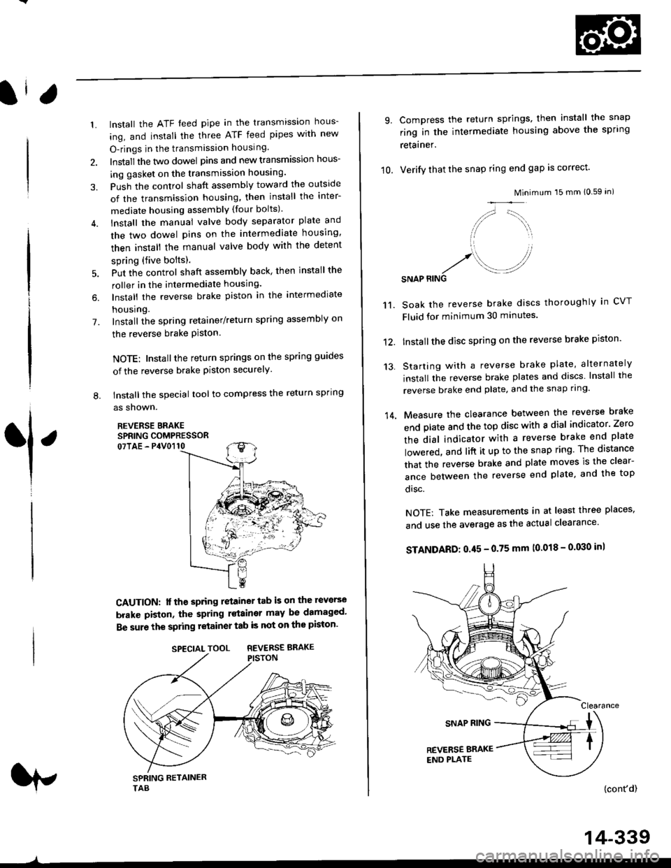
tnstall the special tool to compress the return spring
as shown.
REVERSE BRAKESPRING COMPRESSOR07TAE - P4V0110
6.
L
1
CAUTION: lf the spring retainer tab is on the reverse
brakc piston, the spring rstainer may be damaged'
Be sure the spring retainer tab is not on the piston'
rp
SPECIALTOOL REVERSEBRAKE
-^
14-339
10.
9.
14.
Compress the return springs, then install the snap
ring in the intermediate housing above the spring
retainer.
Verify that the snap ring end gap is correct'
Mini
/,,- '-t,,,,.
// \i/ ',r
'1 ,
.r' //'/. .-J?RINGSNAP
mum 15 mm 10.59 in)
Soak the reverse brake discs thoroughly in CVT
Fluid for minimum 30 minutes.
Installthe disc spring on the reverse brake piston'
Starting with a reverse brake plate, alternately
install the reverse brake plates and discs lnstall the
reverse brake end plate, and the snap ring'
Measure the clearance between the reverse brake
end plate and the top disc with a dial indicator' Zero
the dial indicator with a reverse brake end plate
lowered, and lift it up to the snap ring The distance
that the reverse brake and plate moves is the clear-
ance between the reverse end plate, and the top
disc.
NOTE: Take measurements in at least three places'
and use the average as the actual clearance'
STANDARD: 0.45 - 0.75 mm (0.018 - 0'030 in)
{cont'd)
11.
12.
13.
Page 1027 of 2189

22. Install the shift cable end on the control lever, and
install the shift cable on the shift cable bracket'
CAUTION: Take care not to bend the shift cable'
23. lnstall the clip in the direction shown.
LOCKNUT
SHIFI CABLE 29 N m {3.0 kg{ m, 22lblftl
SHIFT CABLEERACKET
WASHERIPLASTIC)
CONTROL LEVER
24, Connect the solenoid harness connector. the drive
pulley speed sensor connector. and the ground
cable terminals.
6x1.0mm12 N.m {1.2 kgf.m.8,7 rbtft)
GROUND CABLETERMINAL 6x1.0mm
GROUNDTERMINAL
12 N.m {1.2 kgf'm,8.7lbtfrl
DRIVE PULLEYSPEED SENSORCONNECTOR
SOLENOID HARNESS
CONNECTOR
25. Connect the starter motor cable on the starter motor.
and install the cable holder.
NOTE: When installing the staner motor cable. make
sure that the crimped side of the ring terminal is
facing out (see section 23).
STARTEB
BMOUNTING NUT
9 N.m (0.9 kgf m,7 lbf ft)
26. Install all removed connectors and clamps'
27. Install the distributor.
28. Install the intake air duct and air cleaner housing
29.
assemDly.
Refill the transmission with the recommended
Genuine Honda CVT Fluid (see page 14-2991
CAUTION: While filling the CvT Fluid, bs surs not io
allow dust and other fotoign particles to entor into
the transmission.
Connect the battery positive (+) terminal first, then
the negative (-l terminal to the battery'
Check the ignition timing (see section 23).
Start the engine. Set the parking brake, and shift the
transmission through all gears three times Check
shift cable adjustment (see page 14-355).
Check the front wheel alignment (see section 18)
Let the engine reach operating temperature (the
radiator fan comes on) with the transmission in lXl
or E position, then turn it off and check fluid level'
Perform the start clutch calibration procedure on
page 14-293.
Road test as described on pages 14-296 and 14-297
30.
31.
34.
36.
STARTER MOTOR
14-351
Page 1052 of 2189

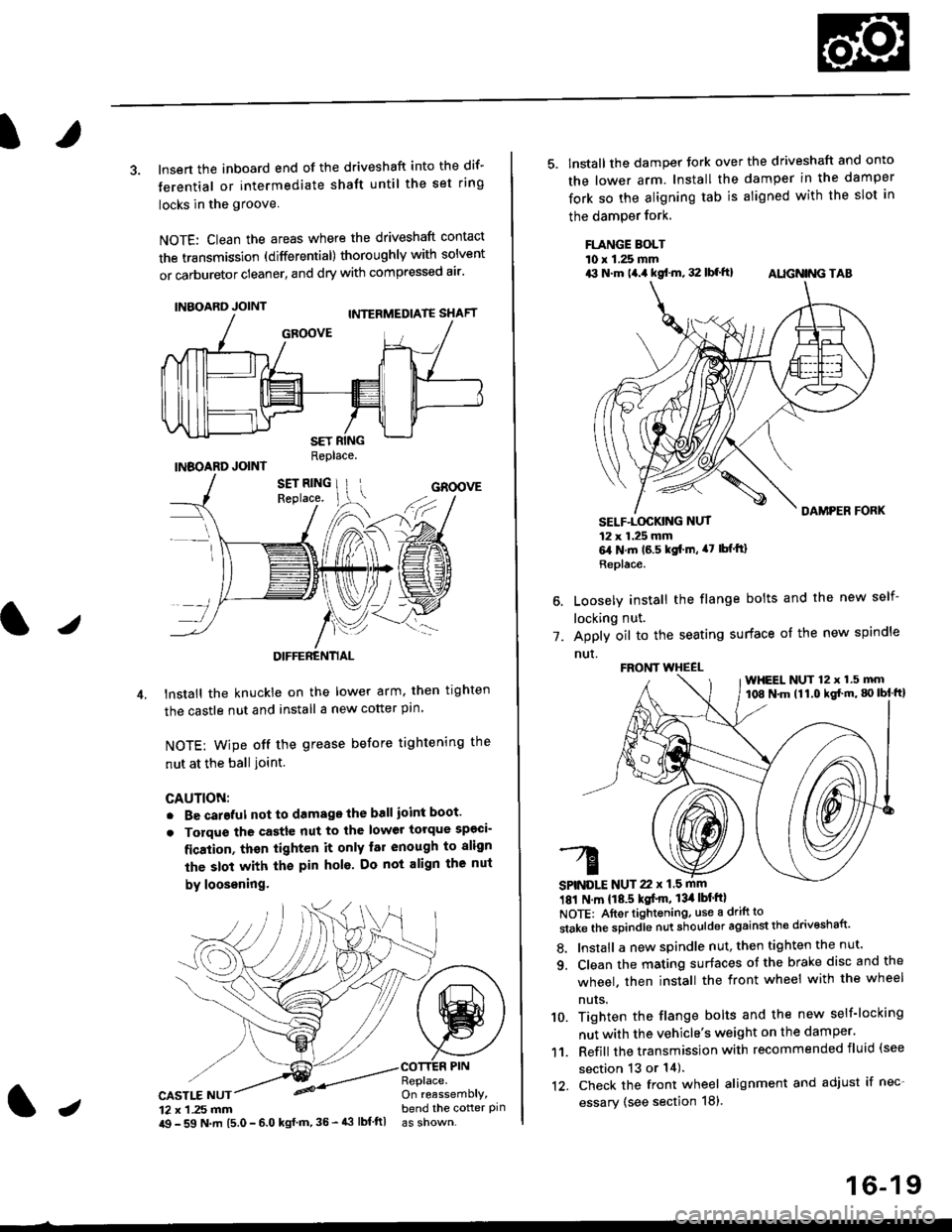
3. lnsert the inboard end of the driveshaft into the dif-
terential or intermediate shaft until the set ring
locks in the groove
NOTE: Clean the areas where the driveshaft contact
the transmission (differential) thoroughly with solvent
or carburetor cleaner, and dry with compressed air'
INBOARD JOINT
INBOARD JOINTReplace.
GROOVE
an
DIFFERENTIAL
lnstall the knuckie on the lower arm. then trghten
the castle nut and install a new cotter pin
NOTE: wipe off the grease before tightening the
nut at the ball ioint.
CAUTION:
. Be careful not to damago the ball ioint boot'
. Torque the castle nut to the lower torque sp€ci-
fication, thsn tighten it only far enough to align
the slot with th€ pin hol6. Do not align the nut
by loosening.
CASTLE NUT12 x 1 .25 mm
COTTER PINReplace.On reassemblY,bend the cotter pinJi$ - 59 N.m 15.0 - 6.0 kgl m,35 - 43 lbf ftl
16-19
5. lnstall the damper tork over the driveshaft and onto
the lower arm. Install the damper in the damper
fork so the aligning tab is aligned with the slot in
the damPer fork.
FLANGE BOLTl0 r 1.25 mmrit N.m t4.a kgf.m, 32 lbf.ft) AIIGN|NG TAB
1.
SELF-LOGKING NUT12 x 1.25 mm6,1N.m 16.5 kgi.m, a7 lbfftl
Replace.
Loosely install the flange bolts and the new self-
locking nut.
Apply oil to the seating surface of the new spindle
nut.
181 N m 118.5 kgt'm, 13il lbt'ftl
NOTE: Aftortightening, use a drift to
stake the spindle nut shoulder against the drivoshaft'
8. Install a new spindle nut, then tighten the nut'
9. Clean the mating surfaces ot the brake disc and the
wheel. then install the front wheel with the wheel
nuts.
10. Tighten the flange bolts and the new self-locking
nut with the vehicle's weight on the damper.
11. Refill the transmission with recommended fluid (see
section 13 or 14).'t2. Check the front wheel alignment and adjust if nec-
essary (see section 18),
FRONT WHEEL
SPINDLE NUT 22 x 1.5 mm
WHEEL NUT 12 x 1.5 mm108 N.m (11.0 kgl'm, g) lbl ftl