1999 HONDA CIVIC Power steering pump
[x] Cancel search: Power steering pumpPage 1088 of 2189
Inspection and Adjustment
Pump Belt
NOTE: When using a new belt, first adjust the deflection
or tension to the values for the new belt, then readjust
the deflection or tension to the values for the used beltafter running engine for five minutes.
Inspection
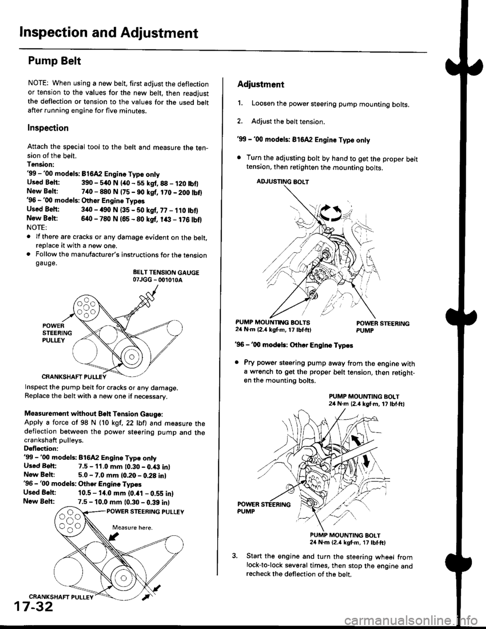
Attach the special tool to the belt and measure the ten-sion of the belt.
Tension:'99 -'00 mod€ls: B1642 Engin. Type onlyUsed Bsh: 390 - 540 N lao - 55 kgt.88 - 120 tbf)New Belt:740 - 880 N {75 - 90 kgf, 170 - 200 tbt}'96 - '00 models: Other Engine Types
Used Beh: 340 - 490 N (35 - 50 kgf, 77 - ilO tbflNew Belt:640 - 780 N 165 - 80 ksf, 1& - 176 tbf)NOTE:
. lf there are cracks or any damage evident on the belt,reDlace it with a new one.. Follow the manufacturer's instructions for the tensiongauge.
BELT TENSION GAUGE07JGG _ 001010A
Inspect the pump belt for cracks or any damage.Replace the belt with a new one if necessary.
Measuremont without Beh Tension Gauga:
Apply a force of 98 N (10 kgt,22 lbfl and measure thedeflection between the power steering pump and thecrankshaft pulleys.
Dsflectior:'99 -'00 model3: 816A2 Engine Typ€ ontyUsed Beh: 7.5 - 11.0 mm t0.30 - 0.43 inlNew Beh:5.0 - 7.0 mm (0.20 - 0.28 in)'96 - '00 models: Othor Engine Typos
Used Behi 10.5 - 14.0 mm (0.ial - 0.59 inlNow Beh:7.5 - 10.0 mm (0.30 - 0.39 inl
POWER STEERING PULUY
CRANKSHAFT PULLEY
17-32
Adiustment
1. Loosen the power steering pump mounting bolts.
2. Adjust the belt tension.
'99 - '00 mod€ls: 816A2 Engin€ Typo only
. Turn the adjusting bolt by hand to get the proper belttension, then retighten the mounting bolts,
ADJUSNNG BOLT
PUMP MOUNNNG BOLTS24 N.m (2.4 kgf'm, 17 tbtftlPOWER STEERINGPUMP
'96 -'00 modek: Othcr Engins Typos
. Pry power steering pump away from the engine witha wrench to get the proper belt tension, then retight-en the mounting bolts.
PUMP MOUNTING BOLT24 N.m (2,4 kgf.m, 17 lbl.ftl
PUMP MOUNTING BOLT24 N.m {2.a kgt m, 17 tbtftl
Start the engine and turn the steering wheel fromlock-to-lock several times, then stop the engine andrecheck the deflection of the belt,
Page 1090 of 2189
lnspection and Adjustment
Pump Pressure Check
Check the fluid pressure as follows to determine
whether the trouble is in the pump or gearbox.
NOTE: First check the power steering fluid level andpump belt tension.
CAUTION: Disconnect the high pr$sure hos€ with care
so as not lo spill the power sieering tluid on tha frame
and other parts.
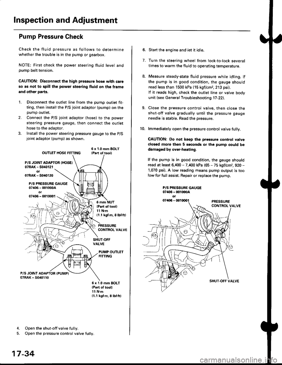
1. Disconnect the outlet line from the Dumo outlet fit-
ting, then installthe P/S joint adaptor (pump) on the
Dumo outlet.
2. Connect the P/S joint adaptor (hose) to the power
steering pressure gauge, then connect the outlet
hose to the adaptor.
3. Install the power steering pressure gauge to the P/Sjoint adaptor (pump) as shown.
ourlEr HosE FnrNo ,t"ll lrilu"ott
P/S JOINT ADAPTOB IHOSEI07RAK - S0i10l2rol07RAK- 50{{)120
P/S PRESSURE GAUGE07406 - 001000Aor07406 - 0010001
4. Open the shut-off valve fully.
5. Open the pressure control valve fully.
17-34
(Pa.t of tooll11 N.m11.1 kgt m, 8 lbf.ftl
PRESSURECONTROL VALVE
SHUT.OFFVALVE
PUMP OUTLETFITTING
6 x 1.0 mm BOLTlPart of tool)11 N.m11.1 kgf m, 8 lbtftl
7.
Start the engine and let it idle.
Turn the steering wheel from lock-to-lock several
times to warm the fluid to operating temperature.
Measure steady-state fluid pressure while idling. If
the pump is in good condition, the gauge should
read less than 1500 kPa (15 kgf/cmr, 213 psi).
lf it reads high, check the outlet line or valve body
unit (see General Troubleshooting 17-22).
Close the pressure control valve, then close the
shut-off valve gradually until the pressure gauge
needle is stable. Read the oressure.
lmmediately open the pressure control valve fully.
GAUTION: Do not keep lhe prossure control valve
clos€d more then 5 soconds or the pump could be
damagod by over-heating.
lf the pump is in good condition, the gauge should
read at least 6,400 - 7,400 kPa (65 - 75 kgflcm,, 920 -
1,070 psi). A low reading means pump output is too
low for full assist. Repair or replace the pump,
9.
P/S PBESSURE GAUGE07{16 -@1@OA
oi
SI{UT.OFF VALVE
Page 1095 of 2189
Power Steering Hoses, Lines
Fluid Leakage Inspection
HOSES and LINES
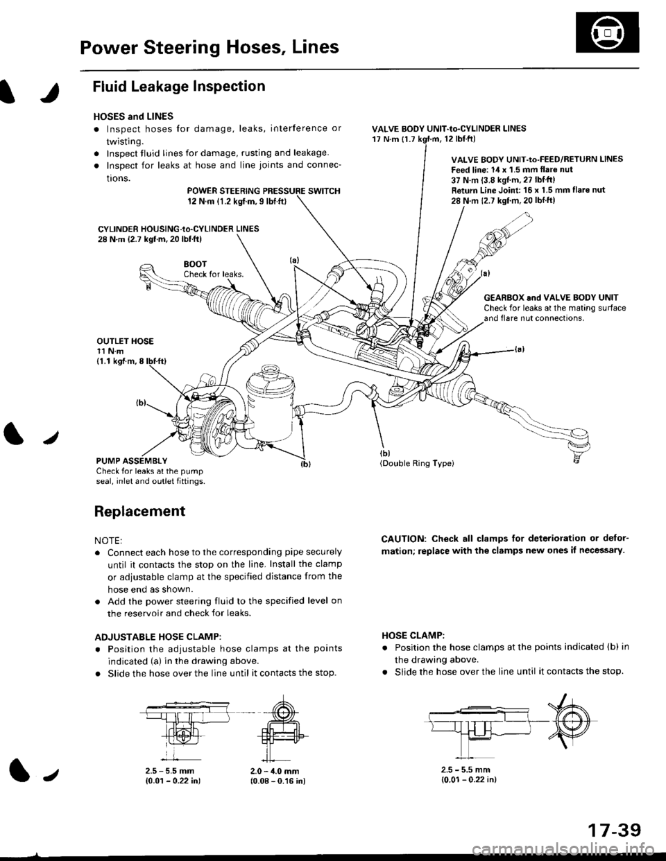
. Inspect hoses for damage, leaks, interference or
twisting.
. Inspect tluid lines for damage, rusting and leakage.
. Inspect for leaks at hose and line joints and connec-
tions.
POWER STEERINGswtTcH12 N.m {1.2 kgt.m,9lbt.ft}
CYLINDER HOUSING-to.CYLINDER LINES28 N.m (2.7 kgf.m, 20 lbf.ft)
VALVE BODY UNIT-to-CYLINDER LINES'17 N.m {1.712 tbl.ftl
VALVE BODY UNIT-Io-FEED/RETURN LINES
Feed line: 14 x '1.5 mm llare nut
37 N.m {3.8 kgJ.m, 27 lbf'tt)
Return Line Joint 16 x 1.5 mm flare nut
28 N m 12.7 kgf.m,20 lbtft)
HOSE CLAMP:
. Position the hose clamps at the points indicated (b) in
the drawing above.
. Slide the hose over the line until it contacts the stop.
8()07Check for leaks.
OUTLET HOSE11 N.m
G€AR8OX and VALVE BODY UNITCheck for leaks at the mating surfaceand flare nut connections,
tbt(Double Ring Typei
CAUTION: Check all clamps for deterioration or delor-
mation; replace with the clamps new ones il necessary.
(1.1 kgf.m,8
PUMP ASSEMBLYCheck for leaks at the pump
seal, inlet and outlet fiftings.
Replacement
NOTE:
. Connect each hose to the corresponding pipe securely
until it contacts the stop on the line. Install the clamp
or adiustable clamp at the specified distance from the
hose end as shown.
. Add the power steering fluid to the specified level on
the reservoir and check for leaks.
ADJUSTABLE HOSE CLAMP:
. Position the adiustable hose clamps at the points
indicated (a) in the drawing above.
. Slide the hose over the line until it contacts the stop.
2.5 - 5.5 mm{0.01 - 0.22 in)2.0 - 4.0 mm(0.08 - 0.16 in)
2.5 - 5.5 mm(0.01- 0.22 in)1.,
17-39
Page 1096 of 2189
Power Steering Pump
RemovaUlnstallation
NOTE: Eefore disconnecting the hoses from the pump,
Dlace a suitable container under the vehicle.
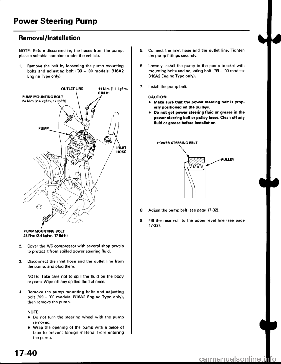
1. Remove the belt by loosening the pump mounting
bolts and adjusting bolt ('99 -'00 models: 81642
Engine Type only).
OUTLET LINE11 N.m {1.1 kgf'm,8
L
PUMP MOUNTING BOLT24 N.m (2.4 kgl.m, 17 lbf ft)
2. Cover the Ay'C compressor with several shop towels
to protect it from spilled power steering fluid.
3. Disconnect the inlet hose and the outlet line from
the pump, and plug them.
NOTE: Take care not to spill the fluid on the body
or parts, Wipe off any spilled fluid at once.
4. Remove the pump mounting bolts and adjusting
bolt ('99 -'00 models: 816A2 Engine Type only),
then remove the pump.
NOTE:
. Do not turn the steering wheel with the pump
removeo.
. Wrap the opening of the pump with a piece of
tape to prevent foreign material from entering
the pump.
17-40
1.
8.
Connect the inlet hose and the outlet line. Tiqhten
the pump fittings securely.
Loosely install the pump in the pump bracket with
mounting bolts and adjusting bolt ('99 -'00 models:
81642 Engine Type only).
Installthe pump belt.
CAUTION:
. Make sure that the power steering belt is prop-
orly positioned on the pulleys.
. Do not get power stoering tluid or grease in the
power steering bsh or pulley faces. Clean off any
fluid or grease before installrtion.
Adjust the pump belt (see page 17-32).
Fill the reservoir to the upper level line (see page
Page 1097 of 2189
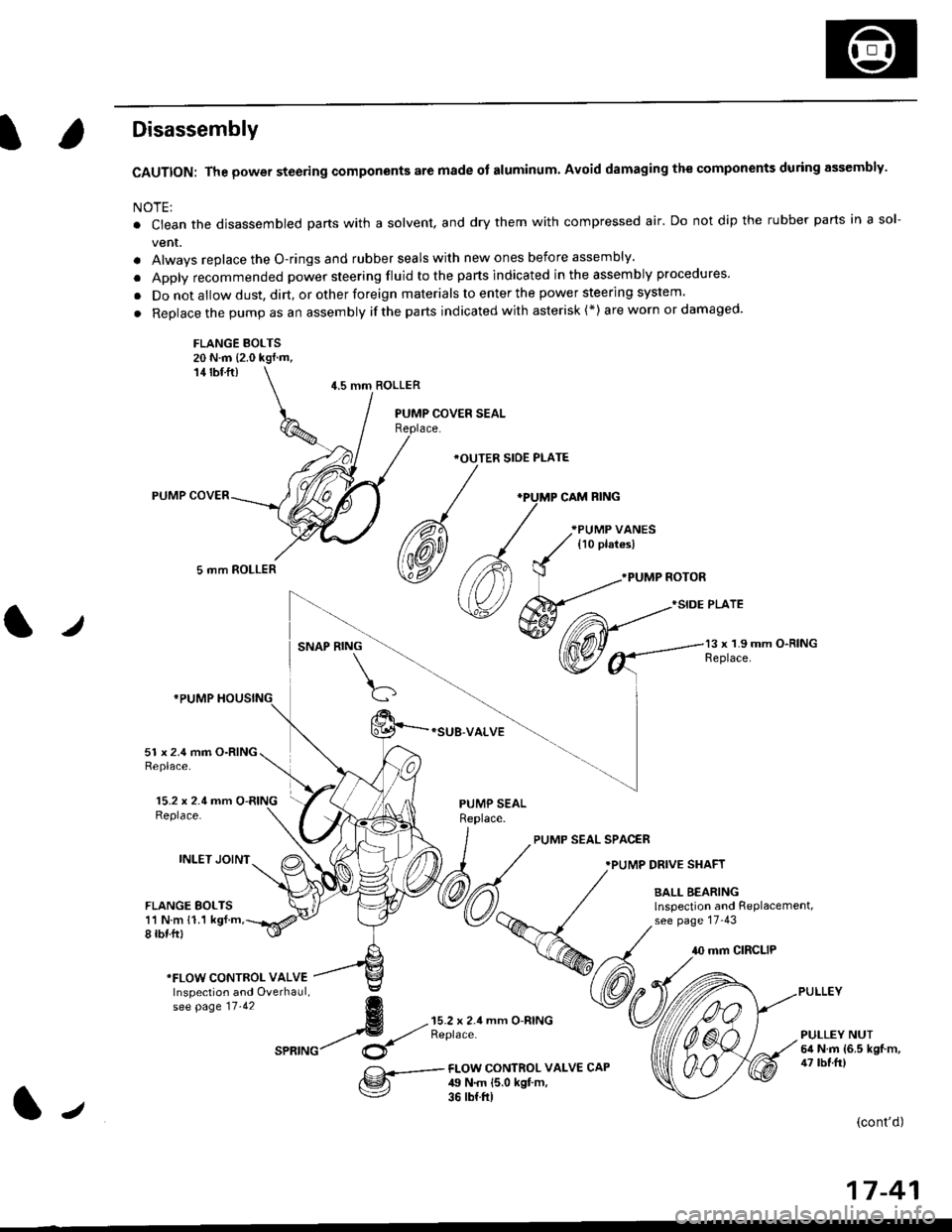
Disassembly
CAUTION: The power steering components are made of aluminum. Avoid damaging the components during assembly.
NOTE:
. Ctean the disassembled parts with a solvent, and dry them with compressed air. Do not dip the rubber parts in a sol-
vent.
. Alwavs replace the O-rings and rubber seals with new ones before assembly.
. Apply recommended power steering fluid to the parts indicated in the assembly procedures'
. Do not allow dust, dirt, or other foreign materials to enter the power steering system.
. Replace the pump as an assembly ifthe parts indicated with asterisk (*) are worn or damaged'
FLANGE BOLTS20 N.m {2.0 kgf.m,14 rbf ft)
5 mm ROLLER
4.5 mm ROLLER
*OUTER SIOE PLATE
*SUB-VALVE
.PUMP NOTOR
}SIDE PLATE
l,/SNAP RING13 x 1.9 mm O-RINGReplace.
15.2 x 2.4 mm O-RINGReplace.
INLET JOINT
51 x 2.4 mm O-RINGReplace.
FLANGE BOLTS11 N m 11.1 kgf.m,8 rbf.ftl
PUMP SEALReplace.
PUMP SEAL SPAC€R
.PUMP DRIVE SHAFT
BALL BEARINGlnspection and RePlacement,see page 17-43
10 mm CIRCLIP
*FLOW CONTROI- VALVEInspection and Overhaul,se[ pase tt.tz g
4 --{;'rX!;'seatuc/ $
mm O-RINGPULLEY NUT6il N.m {6.5 kgf.m,47 tbf.frlFI-OW CONTROL VALV€ CAP49 N.m {5.0 kgt m,36 rb{.ft)
(cont'd)
17-41
J
Page 1098 of 2189
Power Steering Pump
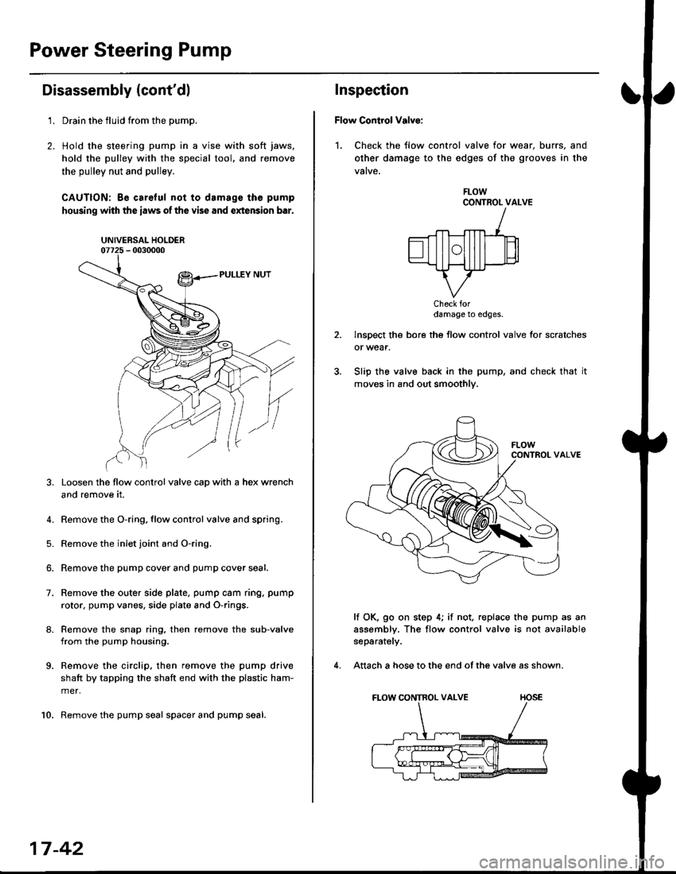
Disassembly (cont'dl
2.
't.Drain the fluid from the pump.
Hold the steering pump in a vise with soft jaws,
hold the pulley with the special tool, and remove
the pulley nut and pulley.
CAUTION: Be careful not to damage the pump
housing with the iaws of the vise and extension bar.
UNIVERSAL HOLDER
Loosen the flow control valve cap with a hex wrench
and remove it.
4. Remove the O-ring, flow control valve and spring.
5. Remove the inlet joint and O-ring.
6. Remove the pump cover and pump cover seal.
7. Remove the outer side plate, pump cam ring, pump
rotor, pump vanes, side plate and O-rings.
8. Remove the snap ring, then remove the sub-valve
from the pump housing.
9. Remove the circlip, then remove the pump drive
shaft by tapping the shaft end with the plastic ham-
mer.
10. Remove the pump seal spacer and pump seal.
17-42
Inspection
Flow Control Valve:
1. Check the tlow control valve for wear. burrs, and
other damage to the edges of the grooves in the
vatve,
FLOWCONTROL VALVE
Check fordamage to edges.
Inspect the bore the flow control valve for scratches
or wear.
Slip the valve back in the pump, and check that it
moves in and out smoothly.
lf OK, go on step 4; if not, replace the pump as an
assembly. The flow control valve is not available
separately.
Attach a hose to the end of the valve as shown.
FLOW CONTROL VALVE TIOSE
4.
Page 1100 of 2189
Power Steering Pump
Reassembly
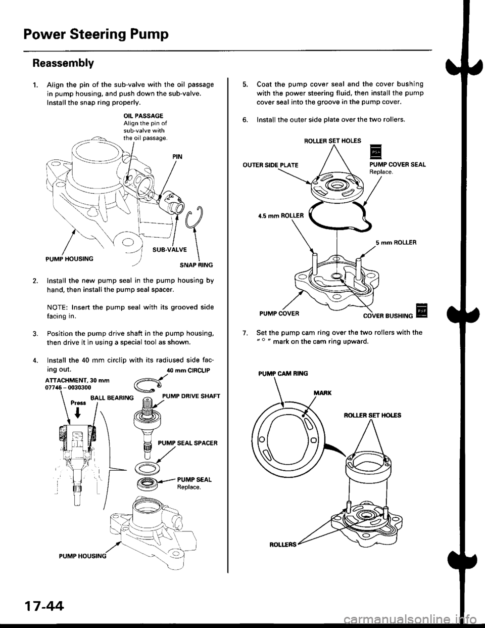
1.Align the pin of the sub-valve with the oil passage
in pump housing. and push down the sub-valve.
Installthe snap ring properly.
OIL PASSAGEAlign the pin of
the oil passage.
PUMP HOUSINGSNAP RING
Install the new pump seal in the pump housing by
hand, then installthe pump seal spacer.
NOTE: Insert the pump seal with its grooved side
facing in.
Position the pump drive shaft in the pump housing,
then drive it in using a special tool as shown.
Install the 40 mm circlip with its radiused side fac-
ing out,
ATTACHMENT, 30 mm
BALL BEARING
40 mm CIRCLIP
d
gf'uMP oRrvE sHAFr
/ffi\
f.\'vj
H PUMP SEAL SPACER
n,/
/:K
/ZA\.-- PUMP SEAL
V Reptace.
17 -44
ROLl.ERS
Coat the pump cover seal and the cover bushing
with the power steering fluid, then install the pump
cover seal into the groove in the pump cover.
lnstall the outer side olate over the two rollers.
ROL1IR
OUTER SIDE PLATE
4.5 mm ROLLER
5 mm ROLLER
PUMP COVERBUSHING
Set the pump cam ring over the two rollers with the" o " mark on the cam ring upward.
7.
ROI,IIR SET HO'"ES
PUMP CAM RING
Page 1101 of 2189
I
8.
9.
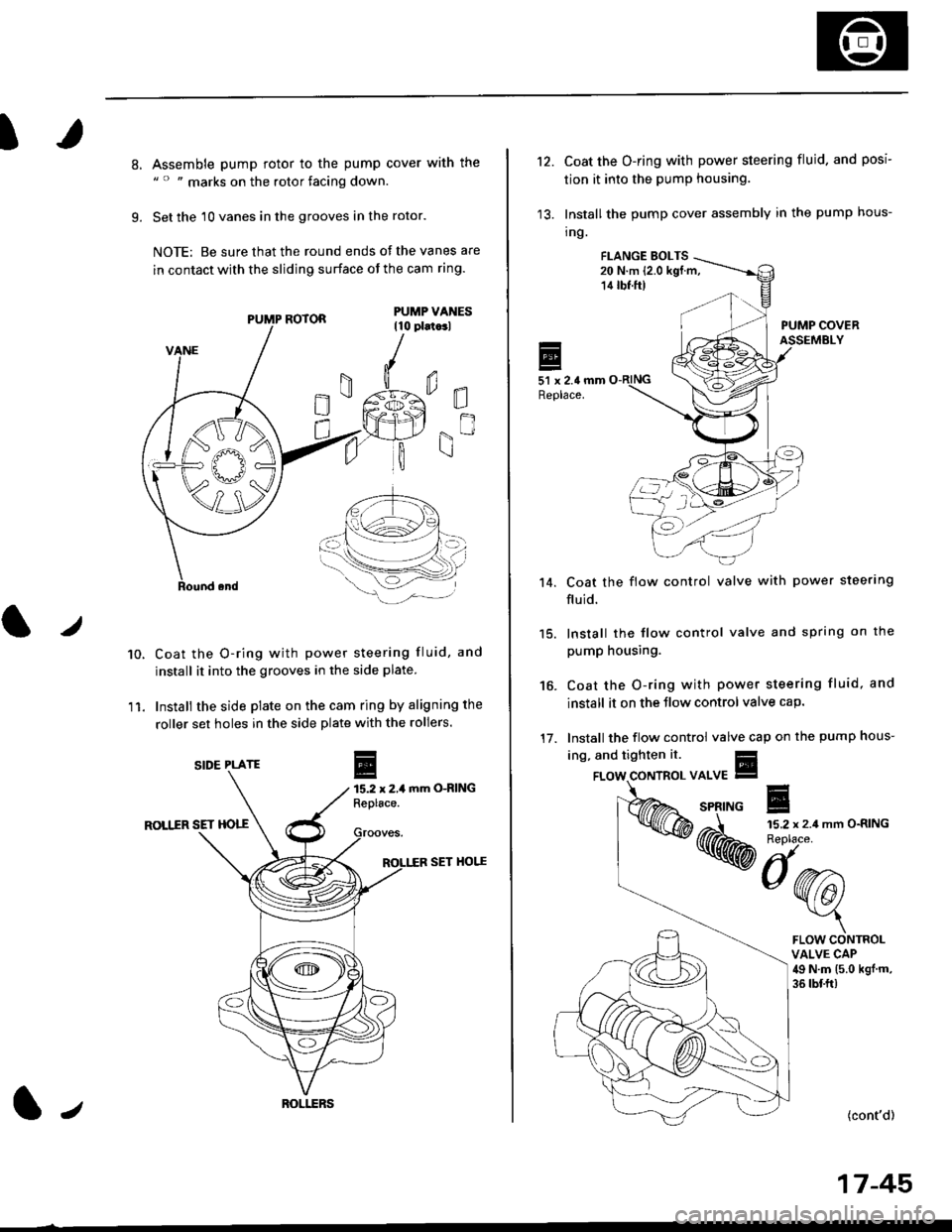
Assemble pump rotor to the pump cover with the" " " marks on the rotor facing down.
Set the 10 vanes in the grooves in the rotor.
NOTE: Be sure that the round ends ot the vanes are
in contact with the sliding surface of the cam ring.
Coat the O-ring with power steering fluid, and
install it into the grooves in the side plate.
Install the side plate on the cam ring by aligning the
roller set holes in the side plate with the rollers.
mm O-RING
ROLIIR SET HOTT
SET HOI.^E
0E
gn
10.
11.
r
E15.2 x 2,1Replace.
PUMP ROTOR
SIDE PLATE
ROI.I.ERSl,
't2.Coat the O-ring with power steering fluid. and posi
tion it into the pump housing.
Install the pump cover assembly in the pump hous-
tng.
FI.ANGE EOLTS20 N.m (2.0 kgf.m,14 tbf.ft)
PUMP COVERASSEMBLY
51 x 2.4 mmReplace.
Coat the flow control valve with power steerlng
fluid.
15. lnstall the flow control valve and spring on the
pump housing.
Coat the O-ring with power steering fluid, and
install it on the Jlow control valve cap.
Install the flow control valve cap on the pump hous-
't 4.
16.
17.
ing, and tighten it.
{cont'd)
17-45
FLOW CONTROLVALVE CAP49 N.m (5.0 kgj m,
36 tbf.ft)