Page 1550 of 2189
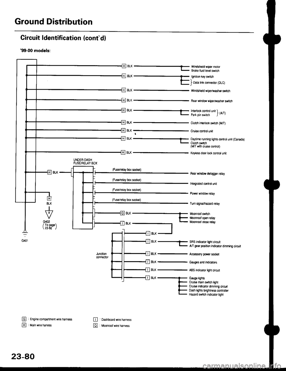
Ground Distribution
Circuit ldentification (conf d)
'99-00 models:
EWir'rdshield wipe. nolorBGke lluid level swildl
6L^ -- €nrnon €y sv loa-)l- i oala hnk conn€clol lDlcl
8LK
BLK
Windshigld dper^vash€r switdt
Re windo wiperlflasher ssitch
BLK
J
To 9aqe23.A2-
tr
E
UNOEN.DASHFUSgRELAYSOX
-r^ -..-- tmenoo( @ rotunn l ._.l- pa* oin swhrh l\4tl
ClLrldr inlerlod swildr (M,T)
Cruis€ confol unit
BL( ---- Oay me running tights controtund (Canadal_ Ctuldt sfich(l,t/T vrith ruis€ cor rol)
Key'ess door lock control unit
(Fuserelay box sockst)
(Fus€/relay box sod(8t)
(Fusdrelay bor sockel)
(Fuserelay box sock€l)
8LK
BLK
BLK
BLK
8LK
near windoYr delogger rclay
htograted co.Ird unil
Tum signal/hazard lelay
SRS indicalor lighl cirqtil,y'T goer position indicator dimming cirdlit
Accessory poxer sod@l
Gaug€s and indicators
ABS indicalor light ciro.lil
Gauge lighbCruis€ main swil$ lEhlCruiso indicator dimming ciroritoash lohls brighlness confolbtHazard s$tdl indicator liohl
G401
(
oh --- Moonroot swnm
t- iroonrool open relay- Moonroot dose reiay
t
fil BLK -J
: Engine @mparlrnenl wire hamess
: Main wire haness
,JUncll0n@nfreclol
E : Dashboard wire harness
El , Mo*tool *ite har"..
23-80
Page 1552 of 2189
Ground Distribution
Circuit ldentification (cont'dl
'99-00 models:(Wilholl ABS)
r'1BL( -< 6 | c40. tFror oaoe 23-BC. II
L
E
UNDEF.H@DFUSF]RELAY BOX
_::I
A,/I gefi posilion swilchELD unil
Servi@ check connector
BL-_14BL- rl--{ry--Browe,mororreray
L4 ,r^ -.;--a-r,* -11-51 BLK - Hearer conrror o6nt n"*-fi-+aLx-lfuBLK- Hearer conrror panel
eLx -iff BLK - ff;?,m",:[:' "n'
or*
ABS glmp motor
_trl
G501
Pos€r door lock cortaol unitDivers door lock aclualorDriver's door lock switchLefl miror delogger
BLK --.+t _
F J Power wndos man swdch
-. Dive/s Fo*gr window motor
TBLK -.1 F--{ BLK - Fighr.niror detogger
tr
tr
E : Healer sub-haness A
El : Healer sub'harress B
: Floor wire hamess
: Drve/sdoorwife haness
-
|,-"*T-"^tl I
vl-L"."
G551
ort,
El ' Main *it" hanes
E : Dashboafd wirc harness
23-82
@ Passenger's doof w're hamess
Page 1565 of 2189
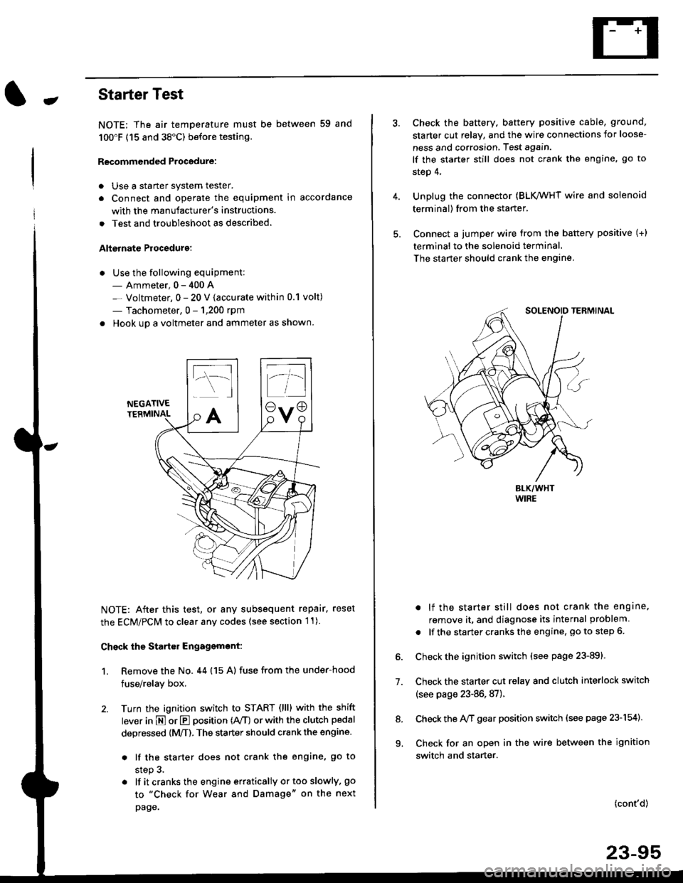
-Starter Test
NOTE; The air temoerature must be between 59 and
100'F (15 and 38"C) before testing.
Recommended Procedure:
. Use a staner system tester.
. Connect and operate the equipment in accordance
with the manufacturer's instructions.
. Test and troubleshoot as described,
Alternate Procedurg:
. Use the following equipment:- Ammeter, 0 - 400 A
- Voltmeter, 0 - 20 V (accurate within 0.1 volt)
- Tachometer, 0 - 1,200 rpm
. Hook up a voltmeter and ammeter as shown.
NEGATIVETERMINAL
NOTE: After this test, or any subsequent repair. reset
the ECM/PCM to clear any codes (see section l1)
Check the Start€r Engagemont:
1. Remove the No. 44 (15 A) fuse from the under-hood
fuse/relay box,
2. Turn the ignition switch to START (llll with the shift
lever in E or E position (rVT) or with the clutch pedal
depressed {M/T). The starter should crank the engine.
. lf the starter does not crank the engine, go to
step 3.
. lf itcranksthe engineerraticallyortooslowly, go
to "Check for Wear and Damage" on the next
page.
Check the battery. battery positive cable, ground,
starter cut relay, and the wire connections for loose-
ness and corrosion, Test again.
lf the starter still does not crank the engine, go to
step 4,
Unplug the connector (BLK,/WHT wire and solenoid
terminal) from the starter,
Connect a jumper wire from the battery positive (+)
terminal to the solenoid terminal.
The starter should crank the engine.
. lf the starter still does not crank the engine,
remove it, and diagnose its internal problem
. lf the startercranksthe engine, goto step 6.
Check the ignition switch (see page 23-891.
Check the starter cut relay and clutch interlock switch
(see page 23-86,87).
Check the A/f gear position switch (see page 23-154).
Check for an open in the wire between the ignition
switch and starter.
7.
(cont'd)
23-95
9.
Page 1579 of 2189
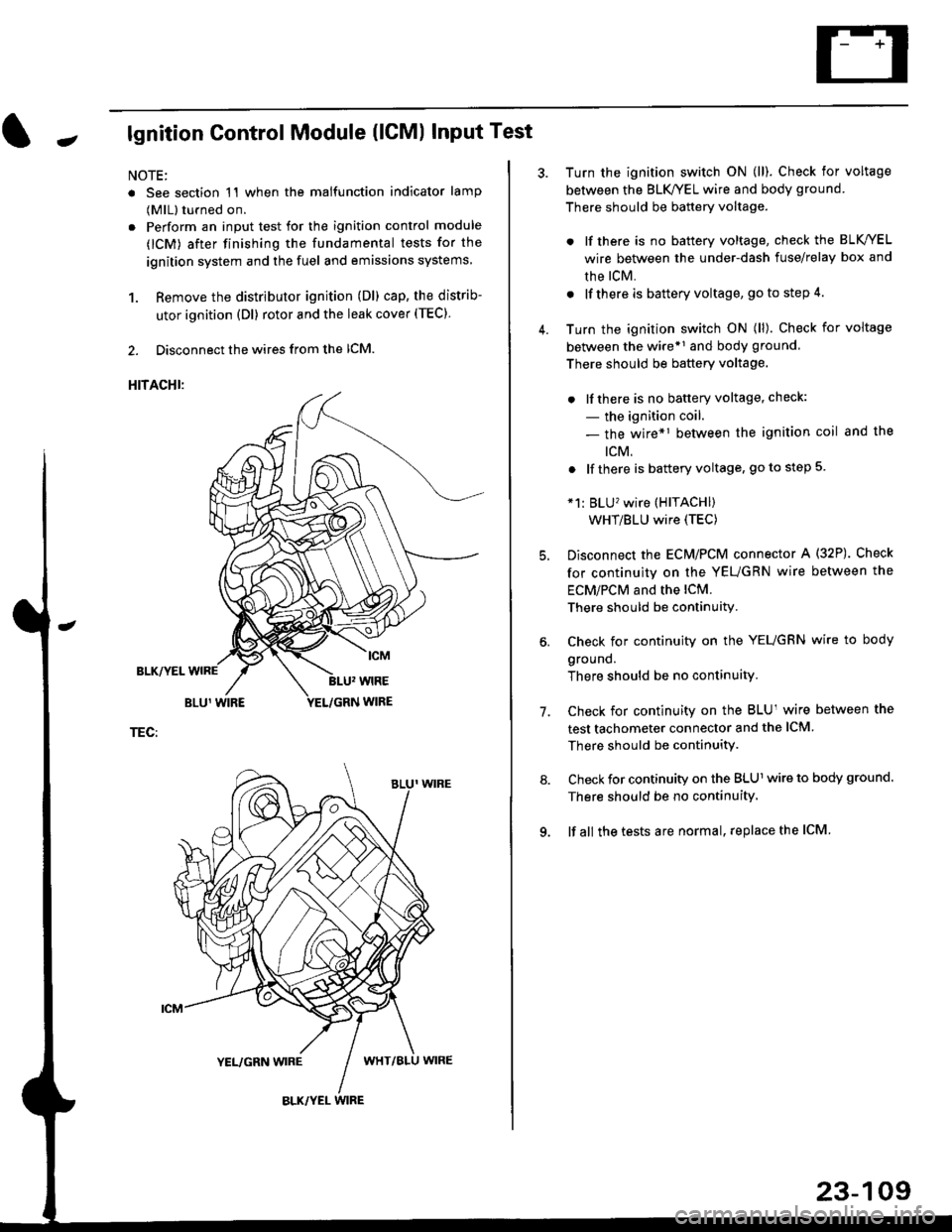
Jlgnition Control Module (lCMl Input Test
NOTE:
. See section 1'l when the malfunction indicator lamp
(MlL) turned on.
. Perform an input test for the ignition control module
(lCM) after finishing the fundamental tests for the
ignition system and the fuel and emissions systems
1. Remove the distributor ignition (Dl) cap, the distrib-
utor ignition (Dl) rotor and the leak cover (TEC).
2. Disconnect the wires from the lCM.
HITACHI:
BLK/YEL
TEC:
Turn the ignition switch ON (ll). Check for voltage
between the BLK/YEL wire and body ground.
There should be battery voltage.
. lf there is no battery voltage, check the BLK/YEL
wire between the under-dash fuse/relay box and
rhe lcM.
. lf there is battery voltage, go to step 4.
Turn the ignition switch ON (ll). Check for voltage
between the wire*r and body ground
There should be battery voltage.
. lfthere is no battery voltage, check:
- the ignition coil.
- the wire*1 between the ignition coil and the
tcM.
. lf there is battery voltage, go to step 5
*1: BLU'�wire (HITACHI)
WHT/BLU wire (TEC)
Disconnect the EcM/PCM connector A (32P). Check
for continuity on the YEUGRN wire between the
ECM/PCM and the lCM.
There should be continuity.
Check for continuity on the YEUGRN wire to body
ground.
There should be no continuity.
Check for continuity on the BLUl wire between the
test tachometer connector and the ICM
There should be continuitY.
Check for continuity on the BLUl wire to body ground.
There should be no continuity.
lf all the tests are normal, replace the ICM
7.
23-109
Page 1585 of 2189
-
Wire side offemale terminals
LtwHT/8LUl
ALTERNATOR 3P CONNECTOR
lCanada)
Wire side oftemale terminals
LIWHT/BLUI
L
{W}IT/BLU)
.+1lr l2l
l3T.l-l-
ir/
(WHT/BLUI
(cont'd)
23-115
{From previous page)
Check tor an open in tho L cir'
cuit-1:1. Turn the ignition switch OFF
2. Disconnect the 4P [3Pl con-
nector from the alternator.
3. Ground the No. 3 terminal of
the 4P l3Plconnector.4. Turn the ignition switch ON (ll)
Turn the ignition swhch OFF, and
rep.ir tho open in tho wHT/
BLU wire.
Does the charging system
light come on?
Check for an open in the L cir-
cuit-2:Disconnect the No 3 terminal o{
the 4P [3PI connector from theground.
Does the charging system
light go off.r
Turn lhe ignition 3whch OFF, and
.epair the 3hort to gtound in the
wHT/Bl-U wire.
ALTERNATOR 4P CONNECTOR(USAI
r?-rl1l2l
FFI
]--
I
I l: canada
Page 1586 of 2189
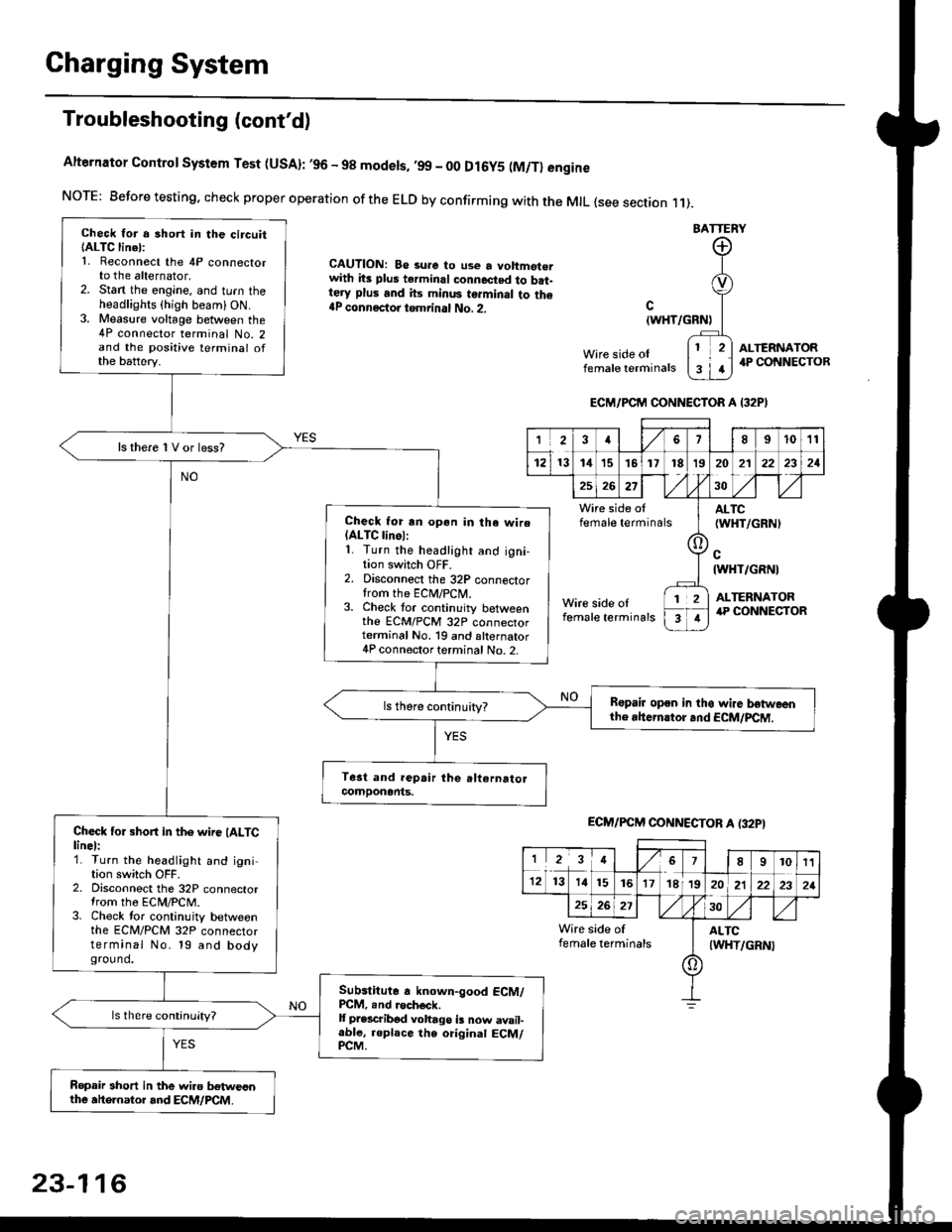
Charging System
Troubleshooting (cont'd)
Alternator Control System Test (USA): ,96 - 98 modets, ,99 _ 00 Dl6y5 (M/Tl engine
NorE: Before testing. check proper operation of the ELD by confirming with the MrL {see section r 1).
BATTERY
CAUTION: Be 3ure to use a voltmot€.with its plus terminal connected to b.t-tery plus and its minus terminal to the{P connectoi tgmrinal No. 2.c
{WHT/GRNt
Wire side oIfemale terminals
ALTERNATOR.P CONNECTOB
Check for a 3hort in the circuitIALTC linel:1. Reconnect the 4P connectorto the alternator,2. Stan the engine, and turn theheadlights {high beam) ON.3. Measure voltage between the4P connector terminal No. 2and the positive terminal ofthe battery.
ls there 1V or less?
Check for rn opon in tha wire(ALTC linol:1. Turn the headlight and igni-tion switch OFF.2. Disconnect the 32P connectortrom the ECM/PCN4.3. Check tor continuity betweenthe ECM/PCM 32P connectorterminal No. 19 and alternator4P connector terminal No. 2.
Bspair open in thg wire lrstweenthe rhern.tor .nd ECM/PCM.
Check for short in the wire (ALTClinel:1. Turn the headlight and ignition switch OFF.2. Disconnect the 32P connectortrom the ECM/PCM.3. Check tor continuity betweenthe ECM/PCM 32P connectorterminal No. 19 and bodyground.
Subslitute a known-good ECM/PCM, .nd .och6ck.It p.escribod vohago i! now avail-able, replace the original ECM/PCM.
Ropair 3hort in the wiro betweonthe ahe.nator and ECM/PCM.
ECM/PCM CONNECTOR A I32PI
'Ia18I1011
121314151718t9
7
202'l2221
262730
Wire side offemale terminalsALTC(WHT/GRNI
c{WHT/GRNI
ALTERNATORWire side oIfemale terminals
([l
T
12
1
ECM/PCM CONNECTOB A (32PI
I23478910t1
1213 14151617182021222321
262730
Wire side of I AITCfemate terminats
A
(WHT/GRN|
23-116
Page 1587 of 2189
-
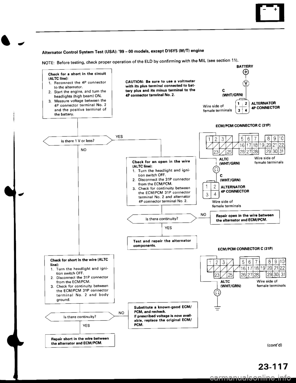
Alternator Control System Test {USA}: '99 - 0O models, except Dl6Y5 {M/T} engine
NOTE: Before testing, check proper operation ofthe ELD by confirming with the MIL (see section 11)'
BATTERY
CAUTION: Be sura lo use a voltmeter
with its plus te.minal conneqted io bat-
tery plus and it3 minus tgrminal to ths
4P connoctot tomrinal No. 2.
Wire side of
female terminals
c(WHT/GRNI
wire side offemale terminals
ALTERNATOR.P CONNECTOR
ECM/PCM CONNECTOR C 13lPI
ECM/PCM CONNECTOR C (31PI
(cont'd)
23-117
Check lor a sho.t in the circuit
{ALTC line):1, Beconnect the 4P connector
to the alternator.
2. Start the engine, and turn the
headlights (high beam) ON.
3. Measure voltage between the
4P connector terminal No. 2
and the Positive terminal of
the battery.
ls there 1 V or less?
Chcck for rn opon in the wire(ALTC lin6l:1. Turn the headlight and igni-
tion switch OFF
2. Disconnect the 31P connector
trom the ECM/PCM.
3. Check for continuity betlveen
the ECM/PCM 31P connectorterminal No. 2 and alternator
4P connector terminal No. 2
Repair opcn in the wire botweon
the alternstoi.nd ECM/PCM.ls there continuity?
Check tor short in the wire IALTC
line):1. Turn the headlight and igni-
tion switch OFF2. Disconnect the 31P connector
from the ECM/PCM.
3. Check for continuity between
the ECM/PCM 31P connector
terminal No. 2 and body
ground.
Substitute a known'good ECM/
PCM, and recheck.It prscribed voltagg is now avail'
abl€, replace tho original ECM/
PCM.
Raoair short in the wite between
the alle.nator and ECM/PCM,
1235618I10
/11611lo191 zo2122
23252621?82930JI
ALTC Wire side of(WHT/GRN) female terminals
o
Page 1610 of 2189
Vehicle Speed Sensor (VSSI
Troubleshooting
Before testing, inspect the No. 15 (7.5 A) fuse in the under-dash fuse/relay box.
TEST HARNESSOTLAJ _ PT3O2OAREO TEST HARNESSCLIP
PROTECTIVETAPE
TEST HARNESSOTLA' . PT3O2OA
(To next page)
Test the BLK wire:1. Disconnect the 3P connectorfrom the vehicle speed sensor(vss).
2. Connect the test harness(07LAJ PT30200) only to theengine wire harness,3. Connect the RED test harnessclip to the positive probe of a
4. Check for continuity betweenthe RED test harness clip andbody ground.
Repair opon in the BLK wireb€twe€n the VSS and G101.ls there continuity?
Te3t the BLK/YEL wire:1. Connect the WHT test harnessclip to the positive probe of avoltmeter, and connectthe REDtest harness clip to the negativeprobe.2. Turn the ignition switch ON {ll).
Repair open in iho BLK/YEL wirebetween the VSS and the under-d6sh tuse/relav box.
vss
GRN TEST HARNESS
RED TEST HARNESS
WHT TEST HARNESS CLIP
23-140