Page 1710 of 2189
Gruise Control
Component Location Index
MAIN SWITCHTesVReplacement,page 23-242CABLE REELReplacement, section 24
BRAKE SWITCH, fest, page 23-244. Pedal Height Adjustment,section 19CRUISE CONTROI. UNITInput Test, page 23-240
swrTcH {M/T). Test. page 23-244. Clutch Pedal Adjustment,section 12
atfSWTTCH. Test, page 23-154' Replac€ment, page 23-'155
ACTUATOR CABLEAdjustment, page 23-246
VACUUM TANK
TOR ASSEMBLY. Test, pag€ 23-245. Replacement, page 23-246. Solenoid Test, page 23-247' Disassembly, page 23-248
23-240
Page 1713 of 2189

)
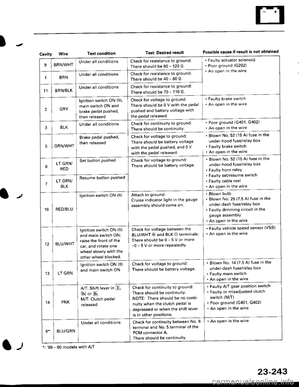
CavityWireTest conditionTest: Desired resultPossible cause if result is not obtained
BRNA/VHTUnder all conditionsCheck for resistance to ground:
There should be 80 - 120 O.
Fau lty actuator solenoid
Poor ground (G202)
An open in the wire
1BRNUnder all conditionsCheck for resistance to ground:
There should be 40 - 60 0.
11BRN/BLKUnder all conditionsCheck for resistance to ground:
There should be 70 - 110 0.
2GRY
lgn jtion switch ON (ll),
main switch ON and
brake pedal pushed,
then released
Check for voltage to ground:
There should be 0 V with the Pedal
pushed and battery voltage with
the pedal released.
'Faulty brake switch
. An open In the wlre
3BLKU nderall conditionsCheck for continuitY to groundl
There should be continuity
' Poor ground (G401, G402)
. An open in the wire
5GRNA,A/HT
Brake pedal pushed,
then released
Check for voltage to groundl
There should be batterY voltage
with the Pedal Pushed. and 0 V
with the pedal released
. Blown No. 52 (15 A) fuse in the
under-hood fuse/relaY box
. Faulty brake switch. An open in the wire
LT GRN/
RED
Set button pushedCheck for voltage to ground:
There should be batterY voltage.
Blown No. 52 (15 A) fuse in the
under-hood fuse/relaY box
Faulty horn relay
Faulty sevresume switch
Faulty cable reel
An open in the wire7LT GRN/
BLK
Resume button Pushed
10RED/BLU
lgnition switch ON (ll)Attach to ground:
Cruise indicator light in the gauge
assembly should come on.
Blown bulb
Blown No. 25 (7.5 A) fuse in the
under dash fuse/relay box
Faulty dimming circuit in the
gauge assemDly
An open in the wire
BLU,A/VHT
lgnition switch ON (ll)
and main swilch ON;
raise the front of the
car, and rotate one
wheel slowly with the
other wheel blocked.
Check for voltage between the
BLUMHT @ and BLK O terminals:
There should be 0- 5 V or more
-0- 5 V or more repeatedlY
. Faulty vehicle speed sensor {VSS)
. An open in the wire
LT GRN
lgnition switch ON (ll)
and main switch ON
Check for voltage to ground:
There should be batterY voltage.
Blown No. 14 (7.5 A)fuse in the
under-dash luse/relaY box
Faulty main switch
An open in the wire
14PNK
A,T: Shift lever in E,
ojorE
M/T: Clutch pedal
released
Check for continuity to ground:
There should be continuity.
NOTE: There should be no conti-
nuity when the clutch Pedal is
depressed or when the shift lever
is in other positions.
Faulty A/f gear position switch
Faulty or misadjusted clutch
switch (M/T)
Poor ground (G401, G402)
An open in the wire
BLU/GRN
Under all conditionsCheck for continuity between No. I
terminal and No. 5 terminal of the
PCM connector A.
There should be continuity
. An open in the wire
*: '99 - 00 models with A,/Tl-,
23-243
Page 1717 of 2189

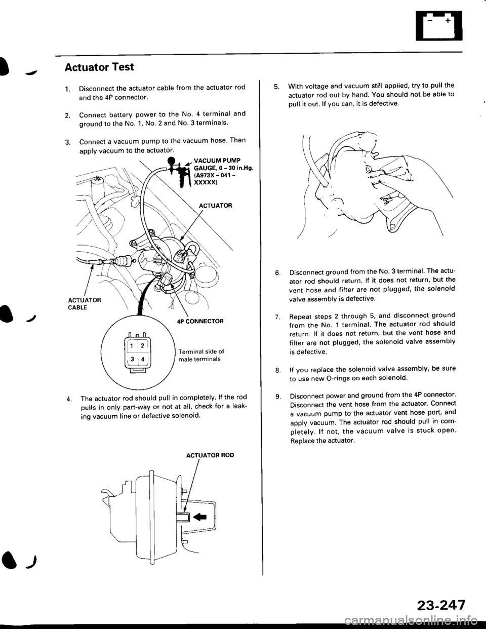
)Actuator Test
't.Disconnect the actuator cable from the actuator rod
and the 4P connector.
Connect battery power to the No 4 terminal and
ground to the No. 1, No. 2 and No. 3 terminals.
Connect a vacuum pump to the vacuum hose Then
apply vacuum to the actuator.
2.
VACUUM PUMPGAUGE,0 - 30 in.Hg.
{A973X - 041 -
xxxxxl
ACTUATOR
,lP CONNEcToR
Terminalside o{male termrnals
4. The actuator rod should pull in completely. lf the rod
pulls in only pan-way or not at all' check for a leak-
ing vacuum line or defective solenoid.
ACTUATOF ROD
l-t
23-247
5. With voltage and vacuum still applied, try to pull the
actuator rod out by hand. You should not be able to
oull it out. ll you can, it is defective
1.
Disconnect ground from the No.3 terminal. The actu-
ator rod should return lf it does not return, but the
vent hose and filter are not plugged, the solenoid
valve assembly is defective.
Repeat steps 2 through 5, and disconnect ground
from the No. 1 terminal. The actuator rod should
return. lI it does not return, but the vent hose and
filter are not plugged. the solenoid valve assembly
is defective.
It you replace the solenoid valve assembly, be sure
to use new O-rings on each solenoid.
Disconnect power and ground from the 4P connector.
Disconnect the vent hose from the actuator. Connect
a vacuum pump to the actuator vent hose port, and
apply vacuum. The actuator rod should pull in com-
pletely. lf not, the vacuum valve is stuck open.
Replace the actuator'
8.
Page 1719 of 2189
)Actuator Solenoid Test
1. Disconnect the 4P connector from the actuator'
ACTUATOR
2. Check for resistance between the terminals accord-
ing to the table.
NOTE: Resistance will vary slightly with tempera-
ture; sDecified resistance is at 70"F (20'C).
SAFETY VALVE
VACUUMVALVE
J
From VENTHOSE
+ To VACUUM
Terminalside otmale terminals
Terminal
Resistance (O) \
234
VENT SOLENOID40 600o---o
VACUUM SOLENOID30- 500G---o
SAFETY SOLENOID40- 600o---o
l)
TANK
23-249
Page 1720 of 2189
Gruise Control
Actuator Disassembly
ACTUAYOR CABLE
0
o
ACTUATOR BRACKET
WIRE SUPPORT BRACKET
ACTUATORTest, page 23 245
SOLENOID VAI-VESTest, page 23 247
SOLENOIDSEAL
I
+*RlAC
E
23-250
Page 1832 of 2189

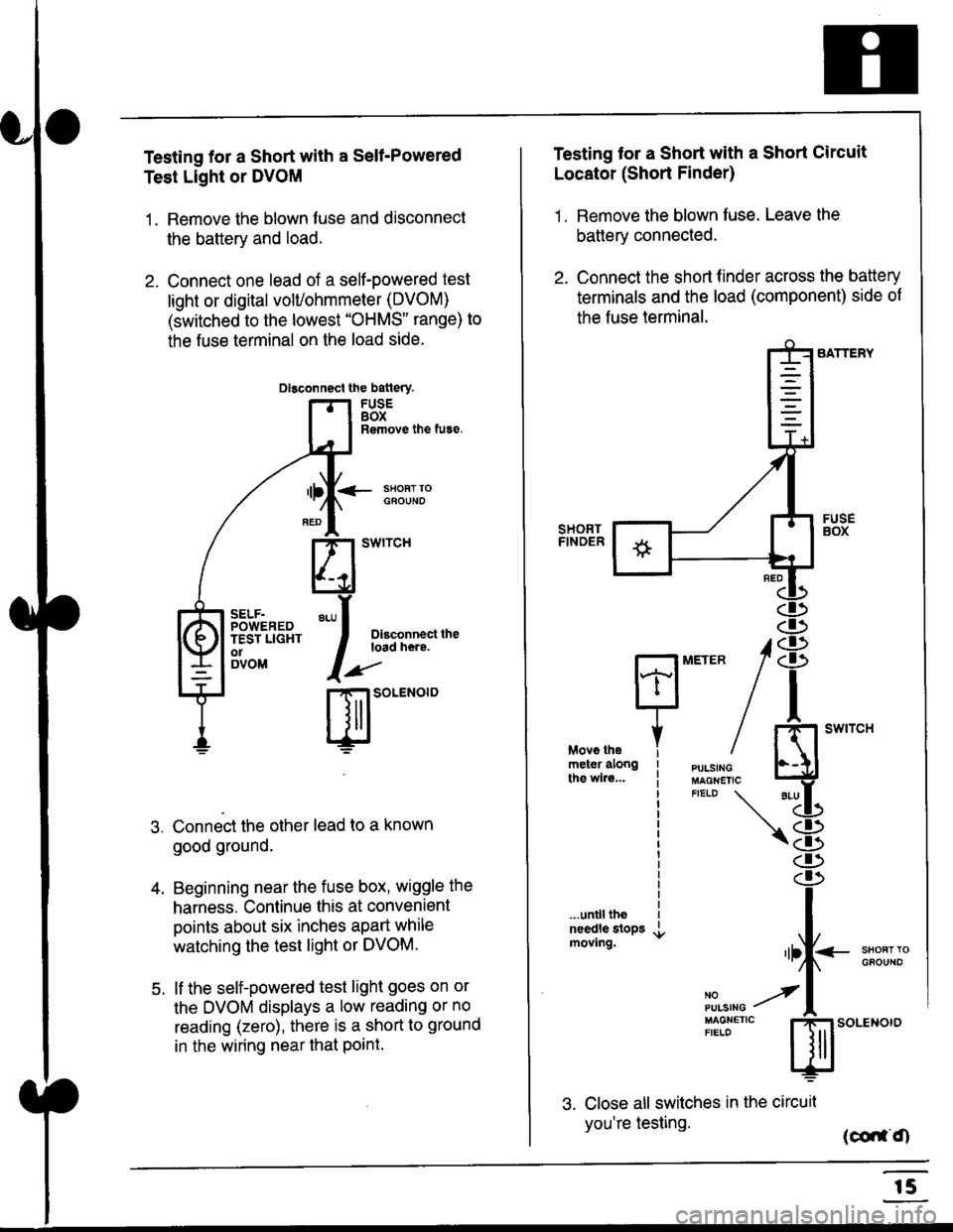
Testing for a Short with a Sell-Powered
Test Light or DVOM
1. Remove the blown fuse and disconnect
the battery and load.
2. Connect one lead of a self-powered test
light or digital volUohmmeter (DVOM)
(switched to the lowest "OHMS" range) to
the fuse terminal on the load side.
Dlsconnect the batlery.
FUSEBOXRemove the fuse.
<- ssoRr rociouNo
Dlsconnect theload here.
.)"'
r| SOLENOID
Connect the other lead to a known
good ground.
Beginning near the fuse box, wiggle the
harness. Continue this at convenient
points about six inches apart while
watching the test light or DVOM.
lf the self-powered test light goes on or
the DVOM displays a low reading or no
reading (zero), there is a short to ground
in the wiring near that Point.
SELF.POWEREDTEST LIGHTo1DVOM
4.
5.
Testing tor a Short with a Short Circuit
Locator (Short Finder)
1 . Remove the blown fuse. Leave the
battery connected.
2. Connect the short finder across the battery
terminals and the load (component) side of
the fuse terminal.
SATTERY
SHORTFINOER
FUSEBOX
PULSINGMAGNETICFIELD \
NOPUISING
\
I swtrcH
I
<- stl
Kl"I- -.T.1
"'at
\8
d)
.r.
rlll<
,l
m
...unilltheneedle slopsmoving.SHOFTTGFOUNO'llt
No --tPULS|NG z
MAGNETTC IFIELD ISoLENOTO
3. Close all switches in the circuil
you're testing. (co,f,O
r5
Page 1840 of 2189

Ground-to-Components I ndex
f.,lONOTE: All ground wires are BLK unless otherwise noted.
GroundPageComponents or Circuit Grounded
Battery (BLKYEL)
Steering pump bracket
t+-rg ITransmission housing
l
G101
(-1)
G101
(-2)
14-2
and
14-3
ano
14-1
Powertrain or engine control module (PG1 and pG2 are BLK: LG1 and LG2 are
BRN/BLK), EGR control solenoid valve (CW, EGR valve and lift sensor (Dt6yS enginewith M,/T), Engine coolant temperature switch, pGM-Fl main relay, power steeringpressure switch (USA), Primary HO2S (D16Y5 engine with l\/,/T), Vehicle speed sensor,VTEC pressure switch (D16Y5/D16Y8 engines), CKF sensor (BRN/BLK), Transmission
control module (CYf) (Pc1 is BLK: LG1 is BRN/BLK)
Shielding betvveen the PCM or ECM and these components (all have BRN/BLK wires):
CKF sensor, TDC/CKP/CYP sensor. Primary and secondary heated oxygen sensors.
Knock sensor (CWDl6YB engine), Mainshaft speed sensor (AiT except CVT),
I Countershaft speed sensor (A/T except CVf)
Shielding between the TCM and these components (CVT) (all have BRN/BLK wires):
Drive pulley speed sensor, Driven pulley speed sensor, Secondary gear shaft
speed sensor
Powertrain or engine control module (PG1 and pG2 are BLK; LG1 and LGz are
BRN/BLK), EGR control solenoid valve (D16Y5 engine), EGR valve (Dt685), Engine
coolant temperature switch, Fuel pressure regulator shut-off solenoid valve (D1685),
PGM-FI main relay, Power steering pressure switch (USA), Vehicle speed sensor, VTECpressure switch (All except D16Y7 engine), CKF sensor (A
except 81642) (BRN/BLK)
Shielding between the PCM or ECM and these components (all have BRN/BLK wires):
CKF sensor, TDC/CKP/CYP sensor, Primary and secondary heated oxygen sensors,
Knock sensor (All except D16Y7 engine), i/ainshaft speed sensor (Arf except CW),
Countershaft speed sensor (A,/T except CVf), Drive pulley speed sensor (CW), Drivenpulley speed sensor (CVT), Secondary gear shaft speed sensor (CVf)
I Badiator fan motor, Right front parking/turn signat tight, Right headtight
G20214-4I Cruise control actuator, Left front parking/turn signal lights, Left headlight, Rear window
I washer motor, Windshield washer motor, Washer fluid level switch (,99-'00 Canada)
G401| +-o
and
14-7
Accessory power socket, Brake fluid level switch, Clutch interlock switch (M/T), Clutchswitch (lillT with cruise/D16Y5 engine with MfD, Combination wiper switch (Z wires),
Cruise control main switch, Cruise control unit, Dash lights brightness controller, Data
link connector, Daytime running lights control unit (Canada), Gauge assembly, Horn('96-'97 models), Integrated control unit, Interlock control unit (ArI), Keyless door lock
control unit ('99-'00 models with keyless), Moonroof close and open relays, Moonroof
switch, Park pin switch (A/r), Power window relay, Rear window defogger relay, Rear
window defogger switch ('96-'98 models), Steering lock, Stereo radio tuner (,96-,98
USA: LX, EX, and HX), Turn signal/hazard relay, Windshield wiper motor.....plus
everything grounded through G402
6-6
Page 1847 of 2189

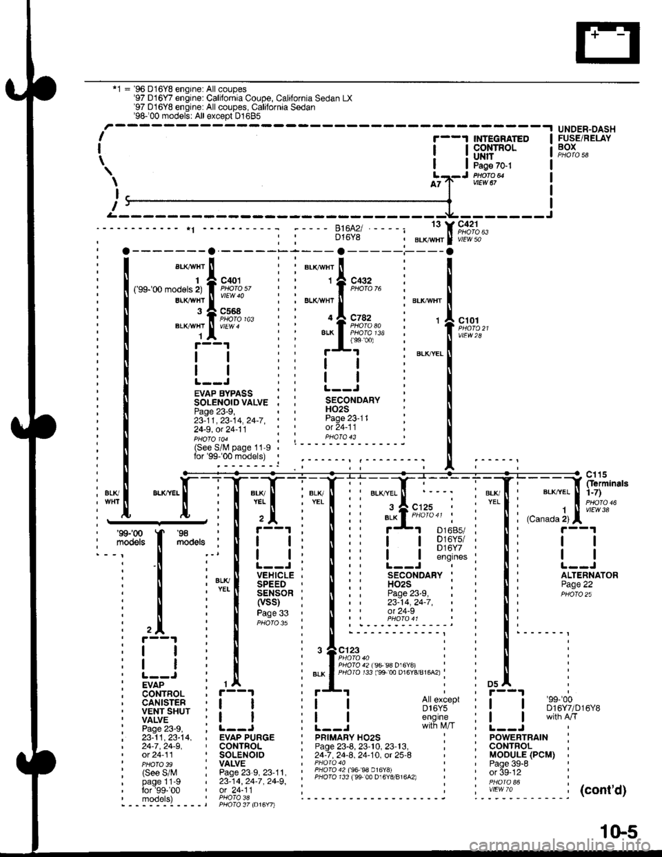
'1 = '96 D16Y8 engine: All coupes'97 D16Y7 engine: California Coupe, California Sedan LX'97 D16YB engine: All coupes, California Sedan'98100 models: All except D1685-.t UNDER-DASHI
I
\
'--1 $NEGRATED
| !s$il:'Ptlofo avtEw 67
c42'lPHO|O 63vlEW 50
ct01
vtEw28
FUSE/RELAYBOX
\
I
T
D16Y8
13
c568
ELKAYTIT
BLKAVHT
1
143
EVAP BYPASS : :SOLENOIDVALVE . ,Page 23-9,23-11,23-14,24-7,' '
24-9, ot 24-11
H02SPage 23-11ot 24-11pHoTolo4 ; ; PHoTo 43(See S/lV page 11-9lor'99-'00 models) ,
i1[
":"[-lT:T
l+Tli'::f;:r i"'{' l;;;]fip;:
I Fs'[
**,
I il i I ii !-l s];$:i i Ii t--l
i ! i'*[ iEi.;*Ti lii
'fl*-i
i li itqii-*
i l il[l?ti
lii iiii;:" i:li
i trr i I i.r^.:.'.'.'i::::;j i !' i
: i i , I i ,+e;::"," i : ! i
itI
i! | i | :".*lfigi3li;ts's"";:tg;u'u^.i : ! :
iv7"-- : rA : *'I i i osl :
; CoNTBOL , r--1
i liiit- i i_j i i_j #s,{;'i' i [__j
ffnih'*'
i 23:11,23-t4, , EVAP PURGE I pRtMARy Ho2s : ' powERTRAtN :| 24-7,24-9, ' CONTFOL ; Page 23-8, 23'10, 23'13, , ; CONTROL ,' ot 24-11 ' SOLENOIO , 24-7 .24-8. 24-10. ot 25-8 ' , MOOULE (PCM) ,' pHoTo 3s : VALVE I PHoro 40 ' ' Paqe 39-8 '
| (see s/M : Pase23-s,23'11, : ii3l311l l3;ll Pl?191,.,"^,, : ' orSe-12 :
' PHoTo 39 I vALvE | ' Paqe 39-6
: (See S/M : Page 23-9, 23'11. ' lHqI94?199 99 0.16Y!i - i ' or 5g-tz :i bi-gllt-g i zs:tq, zc-i, zc-g', ' PHoro 733 ree 00 D16Y8/816A2) i '. in6i "i i
:':1T:9' ',91"?i'l; i------ ------j ".-':-*-'1. -----j(cont'd)- - - -::-:-l - - - - t PHO\O 37 to16Y7l
1(}5