Page 1618 of 2189
Interlock System
Park Pin Switch Test
1, Remove the front console (see section 2Ol.
Disconnect the 4P connector from the park pinswitch.
Check for continuity between the No. 3 and No. 4terminals with:- the shift lever any position other than E, or- the push button pushed in E.There should be continuity.
Check for continuity between the No. 3 and No. 4terminals with the shift lever in E and the push but-ton released. There should be no continuiw. lf nec-essary, replace the park pin switch.
NOTE: Park pin switch 4p connector No. 1 and No.2terminals are lor Ay'T gear position console light.refer to the circuit diagram on page 23-1S0.
23-14A
Page 1623 of 2189

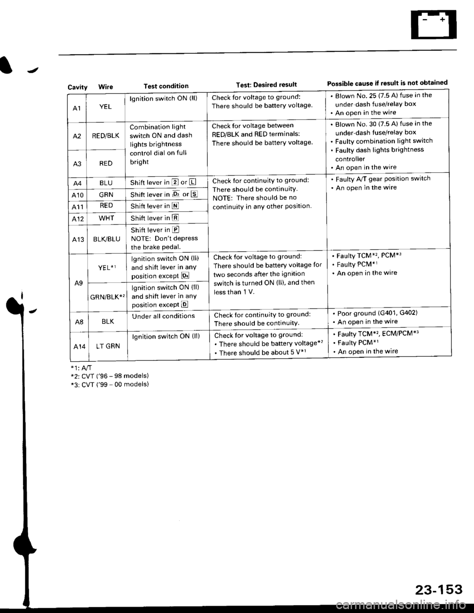
Test conditionTest: Desired resultPossible cause it result is not obtainedCavity
AIYEL
lgnition switch ON (ll)Check for voltage to ground:
There should be banerY voltage.
. Blown No.25 (7.5 A) fuse in the
under dash fuse/relay box
. An open in the wire
A2RED/BLK
Combination light
switch ON and dash
lights brightness
control dial on full
bright
Check for voltage between
RED/BLK and RED terminals:
There should be batterY voltage.
Blown No. 30 {7.5 A) fuse in the
under-dash tuse/relay box
Faulty combination light switch
Faulty dash lights brightness
controller
An open in the wireA3RED
BLUShift lever in P or ICheck for continuity to ground:
There should be continuitY
NOTE: There should be no
continuity in anY other Position.
. Faulty A/T gear Position switch
. An open in the wire
A10GRNShift lever in E or E
A11REDShift lever in E
412WHTShift lever in E
A13BLK/BLU
Shift lever in E
NOTE: Don't depress
the brake pedal.
A9
YEL+ ]lgnition switch ON (ll)
and shift lever in any
position except Pi
Check for voltage to ground:
There should be battery voltage for
two seconds after the ignition
switch is turned ON (ll), and then
less than 'l V.
Faulty TCM*'�, PCM*3
Faulty PCM*r
An open in the wire
GRN/err*'
lgnition switch ON {ll)
and shift lever in anY
position except E
A8BLKUnder all conditionsCheck for continuitv to ground:
There should be continuitY.
. Poor ground (G401, G402)
. An open in the wire
414LT GRN
lgnition switch ON (ll)Check for voltage to ground:
. There should be baftery voltage*'�
. There should be about 5 V*r
Faulty TCM*'�, ECM/PCM*'
Faulty PCM*1
An open in the wire
*2: CVT ('96 - 98 models)*3r CVT ('99 - 00 modelsl
23-153
Page 1624 of 2189
A/T Gear Position Indicator
A/T Gear Position Switch Test
1. Remove the front console (see section 2O).
2. Disconnect the 14P connector from the A/T gear position switch.
3. Check for continuity between the terminals in each switch position according to the table.
' Move the shift lever back and forth without pushing the shift lever at each switch position, and check for continuitywithin the range of free play of the shift lever.' lf there is no continuity within the range of free play, adjust the position of the switch as described on the nextpage.
Terminal side of male terminals
A/T Gear Position Switch
+ 1 : With cruise controlsystem
23-154
Eack - upLight SwitchNeutralPosition Switch
Page 1625 of 2189

A/T Gear Position Switch
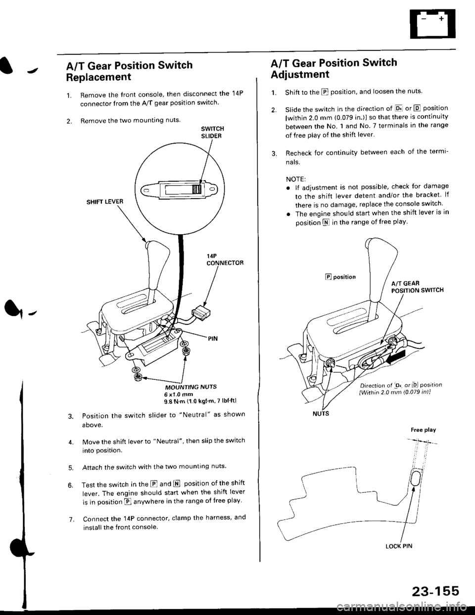
Replacement
1.
2.
7.
Remove the front console, then disconnect the
connector from the A/f gear position swltch
Remove the two mounting nuts
swrTcHSLIDEB
MOUNT'NG NUTS6x1 0mm98Nm(10kgtm'7lblftl
Position the switch slider to "Neutral" as shown
above.
Move the shift lever to "Neutral", then slip the switch
into position.
Aftach the swjtch with the two mounting nuts.
Test the switch in the E and E position ofthe shift
lever. The engine should start when the shift lever
is in position fl anywhere in the range of free play
Connect the 14P connector, clamp the harness, and
install the front console
14P
A/T Gear Position Switch
Adjustment
1.
3.
Shift to the E position, and loosen the nuts.
slide the switch in the direction of El or E position
lwithin 2.0 mm (0.079 in.)l so that there is continuity
between the No. 1 and No 7 terminals in the range
of free play of the shift lever'
Recheck for continuity between each of the termi-
nats.
NOTE:
. lf adjustment is not possible, check for damage
to the shift lever detent and/or the bracket lf
there is no damage. replace the console switch
. The engine should start when the shift lever is in
position N in the range of free play
E positionA/T GEARPOSITION SWITCH
Djrection of -on, or Dl Positionlwithin 2.0 mm (0.079 in)1
Free play
-lfr-
LOCK PIN
23-155
Page 1713 of 2189

)
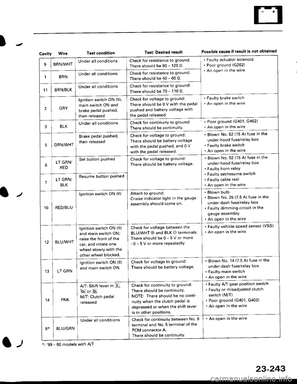
CavityWireTest conditionTest: Desired resultPossible cause if result is not obtained
BRNA/VHTUnder all conditionsCheck for resistance to ground:
There should be 80 - 120 O.
Fau lty actuator solenoid
Poor ground (G202)
An open in the wire
1BRNUnder all conditionsCheck for resistance to ground:
There should be 40 - 60 0.
11BRN/BLKUnder all conditionsCheck for resistance to ground:
There should be 70 - 110 0.
2GRY
lgn jtion switch ON (ll),
main switch ON and
brake pedal pushed,
then released
Check for voltage to ground:
There should be 0 V with the Pedal
pushed and battery voltage with
the pedal released.
'Faulty brake switch
. An open In the wlre
3BLKU nderall conditionsCheck for continuitY to groundl
There should be continuity
' Poor ground (G401, G402)
. An open in the wire
5GRNA,A/HT
Brake pedal pushed,
then released
Check for voltage to groundl
There should be batterY voltage
with the Pedal Pushed. and 0 V
with the pedal released
. Blown No. 52 (15 A) fuse in the
under-hood fuse/relaY box
. Faulty brake switch. An open in the wire
LT GRN/
RED
Set button pushedCheck for voltage to ground:
There should be batterY voltage.
Blown No. 52 (15 A) fuse in the
under-hood fuse/relaY box
Faulty horn relay
Faulty sevresume switch
Faulty cable reel
An open in the wire7LT GRN/
BLK
Resume button Pushed
10RED/BLU
lgnition switch ON (ll)Attach to ground:
Cruise indicator light in the gauge
assembly should come on.
Blown bulb
Blown No. 25 (7.5 A) fuse in the
under dash fuse/relay box
Faulty dimming circuit in the
gauge assemDly
An open in the wire
BLU,A/VHT
lgnition switch ON (ll)
and main swilch ON;
raise the front of the
car, and rotate one
wheel slowly with the
other wheel blocked.
Check for voltage between the
BLUMHT @ and BLK O terminals:
There should be 0- 5 V or more
-0- 5 V or more repeatedlY
. Faulty vehicle speed sensor {VSS)
. An open in the wire
LT GRN
lgnition switch ON (ll)
and main switch ON
Check for voltage to ground:
There should be batterY voltage.
Blown No. 14 (7.5 A)fuse in the
under-dash luse/relaY box
Faulty main switch
An open in the wire
14PNK
A,T: Shift lever in E,
ojorE
M/T: Clutch pedal
released
Check for continuity to ground:
There should be continuity.
NOTE: There should be no conti-
nuity when the clutch Pedal is
depressed or when the shift lever
is in other positions.
Faulty A/f gear position switch
Faulty or misadjusted clutch
switch (M/T)
Poor ground (G401, G402)
An open in the wire
BLU/GRN
Under all conditionsCheck for continuity between No. I
terminal and No. 5 terminal of the
PCM connector A.
There should be continuity
. An open in the wire
*: '99 - 00 models with A,/Tl-,
23-243
Page 1848 of 2189
Power Distribution
- From Fuses to Relays and Components (cont'd)
@
FUSE 24{PAr/ FELAY}{S/R RELAY)?
_____
s7
FUsE 25 IMETEF I-------r-----l rII\IA6JI r*r tttrecnlreo \-
| | lcoNrRoLUNlr \
I i iPaseTo \
I L__Jlj:p,l2uo II vtt|| bl
tf
lt.---l--- "---t I---r--'g- -------Jcs01 '16YC419
PHata'a ' a PHolo 6"vtEw 55 ' yEL a vtEw 49
:t
i;l-l-l. i
'ttlll
:rttl' L--J !-,J. SHIFT INTERLOCK .
: LocK coNTRoL ,
; SOLENOID UNIT' Page 138 Page 138 I' or 138-1 or 138-1I DHOTO 7- D4O|O 69I vtFW26
'AT ---------
.-- A/T --.
"..ij#j--
",li,,lii"lii-lii^,li".l-l
i------------::r::-:-::'::---::r:-:-:--T--------1
tl
tl
alt------- --------J
.I POWER
I wrNDow
1 RELAYj Page 120
uorlI
I
c501 17C420 11
r::1
I uorr I
ll
MOONROOFOPEN RELAYPage 122ot 122 1
r=?1
I uorr I
ll
MOONROOFCLOSE RELAYPage 122ot 122-1
vtEw 13
(Not (NotUsed) Used)
ABSCruiseControlShift-upInorcalor 'r _
t
GAUGE ASSEMBLYPages 80, 80-1, 80'2,80-3, 81, 89, and 89-1
10-6
Page 1886 of 2189
PGM-FI (All '9G'98 Models except Dl685; '99r0O D16y5 with M/T)
TRANSMISSIONCONTROLMODULE (TCM)
llEv/ 69
ECM ECMcontrol controlReference data datavollage inDutNREF) OMA}:q{.J
(VREF) OMA) OMB)Reference ECM ECMcontroldatajnput
EGRcontrol shift' I solenoid
i
-l
"""'"x :i1",'
sofenoid lock Pa(klvave Circult neutr; I vave circuit neutral| | control control inPut, ! (EsOLr {sru, (A}FNP):L------
voltag€ controldataoutput
I
{
ta
i;;;;';;
."
*
'i\,
' circuit neutral Reverse D4 D3 2 indtcator, ;' control input input input input input control | -,| (sLU) rAlPNPr TATPFI {ATpO4i dlPD3) tAfPzr rDa rNDl | /
[J=:ITTIT'{t
' Interlock See Automatrc: Svstem Transmission Controls I
i i controt
i
"'J;:;;,.,"^,
!
l1l
"lL
:1,.
i
".f:;;,.,"^, 1.,."n,
: I lt ti.."stEBkTJBi ""il*l"*
: | /" I SOLENOTD VALVE
i \J PHaro 12a I
i
t'i!",,,
Bi"ifit**1
';
i l ;;;a ',, pase 14 !'#$tl ii{"Ff*,
i
*-1.
---f !.gg1mr..
' 4 cror| - PHAfO 123
23-6
Page 1923 of 2189

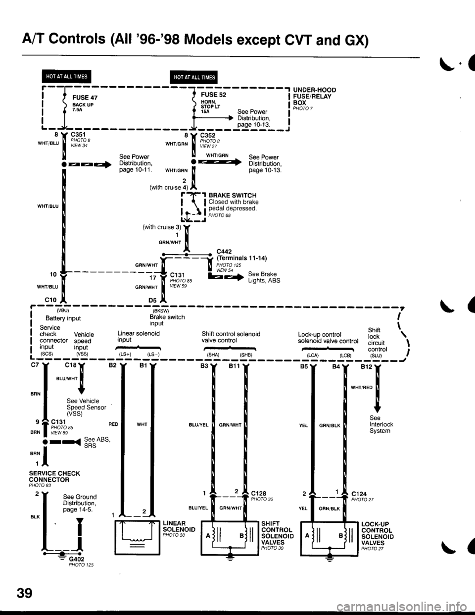
A/T Controls (All '96-'98 Models except CW and GX)
r.(
r5A see power I
--li$"i':,--iL-.At----- __*____..,,53-j"i__8 Y 93^s_1- 8Y C352'"'".u
I iii'i"' ""'o"* | i#?1o.'
ll see power ll wrr cnn See Power
la--- oisirioution, ! -t 6iri,iortion,
[--*
t"*tr*t1,'.':,:;i. wHr GFN lt page 10-13.
,i(with crurse 4) Al"'rl(-1 BRAKE swrrcH
| lClosed.with brake
Ir-I Il,?,|fll,"P'"""oL*--J
c18lr 82
"ar-"t I
I
See VehicleSpeed Sensor(vss)
ct31PHO|O 35vtEw 59
r< See ABs'
UNDER"HOODFUSE/RELAYBOXI
I
I
BFN
9
BFN
o
""il
SERVICE CHECKCONNECTOR
See GroundDistribution,page 14-5.
I
YEL
c124
L__lH:""".: G402
SHIFTCONTROLSOLENOIDVALVES
LOCK-UPCONTROLSOLENOIDVALVES
,. L ---- - - --.#ku" :::::'o f
---------tty"c;11,, l;-,f l;?t?:if,-:;tr *";.!, *"
c10 ,| Ds^'
I Lvou, (SKSV,
! Battery input Brake lwitch I
service nPUt ehin t;;;;i- Vehrcte Linear sotenoid Shift controt sol€noid Lock-up conkol iJ'[
'\
connector speed input valve conhol solenoid vatve controt tliiJ"it \uo trut tconrrol t: (scs) (vss) {Ls}) rLs ) {sHA' {SHB, (LCA) (LCB) {S-U) .--:-'--J
ct28
39
GFN/ALK
(