Page 1616 of 2189

Interlock System
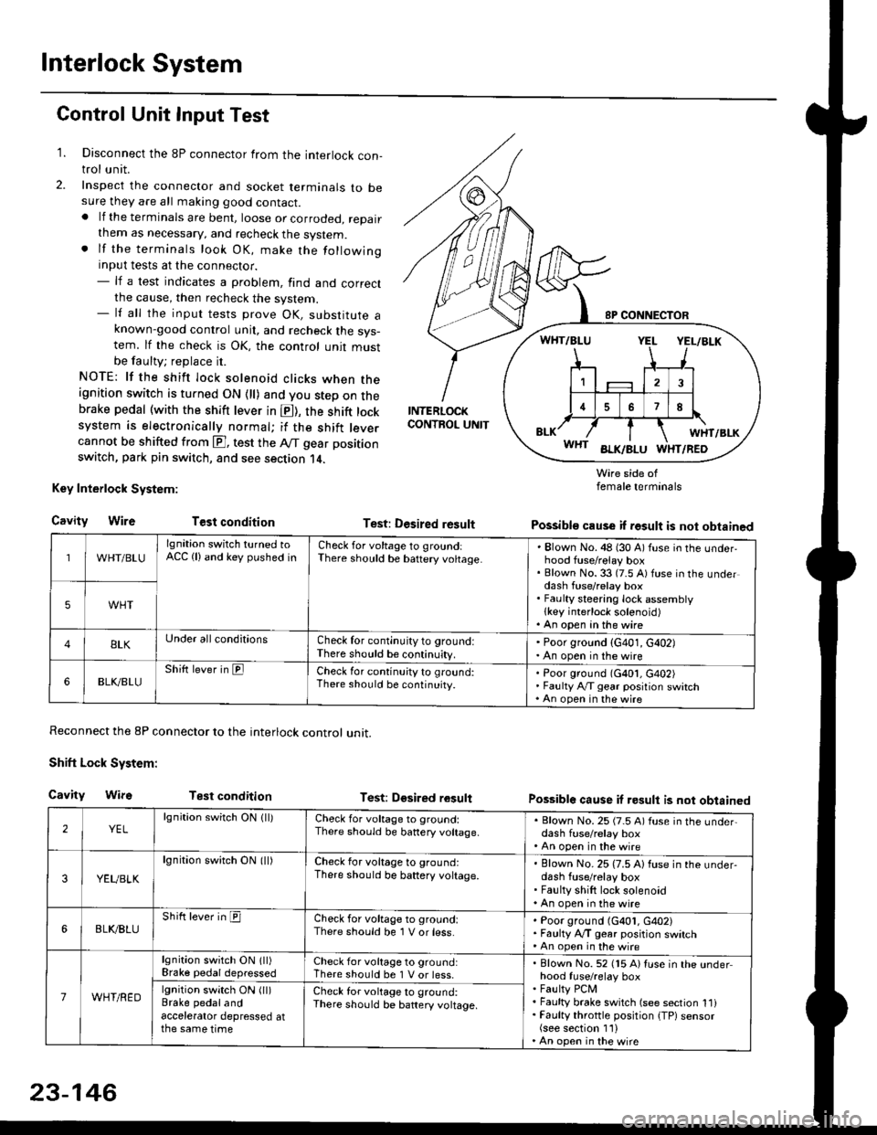
Control Unit Input Test
1. Disconnect the 8P connector from the interlock con-trol unit.
2. Inspect the connector and socket terminals to besure they are all making good contact.. lf the terminals are bent, loose or corroded, repairthem as necessary, and recheck the system.. lf the terminals look OK, make the followinginput tests at the connector.- lf a test indicates a problem, find and correctthe cause, then recheck the system.- lf all the input tests prove OK, substitute aknown-good control unit, and recheck the sys-tem. lf the check is OK, the control unit mustbe faulty; replace it.
NOTE: lf the shift lock solenoid clicks when theignition switch is turned ON {ll) and you step on thebrake pedal (with the shift lever in E), the shift locksystem is electronically normal; if the shift leve.cannot be shifted from E], test the Aff gear position
switch, park pin switch, and see section 14.
Key Interlock System:
CavityWireTest condition
Reconnect the 8P connector to the interlock control unit.
Shift Lock System:
Cavity WifsTest condition
INTERLOCKCONTROL UNIT
Test: Desired result
Test: Dgsired result
Wire side offemale terminals
Possible cause if result is not obtained
Possible cause if result is not obtained
WHT/BLU
lgnition switch turned toACC (lland key pushed inCheck for voltage to groundiThere should be baftery voltage.Blown No. 48 (30 A) fuse in the underhood fuse/relay boxBlown No. 33 (7.5 A) fuse in the underdash fuse/relay boxFaulty steering lock assemblylkey interlock solenoid)An open in the wire
5WHT
BLKUnder all conditionsCheck for continuity to ground:There should be continuity.
' Poor ground (G401, G402). An open in the wire
6BLK./BLUShift lever in ElCheck for continu;ty to ground:There should be continuity.Poor ground (G401, G402)Faulty Ay'T gear position switchAn open in the wire
2YELlgnition switch ON lll)Check for voltage to ground:There should be banery voltage.
. Blown No. 25 (7.5 A) fuse in the under,dash fuse/relay box. An open in the wire
3YEUBLK
lgnition swirch ON (ll)Check for voltage to ground:There should be baftery voltage.Blown No. 25 (7.5 A) fuse in the under-dash fuse/relay boxFaulty shift lock solenoidAn open in the wire
6BLI(BLUShift lever in ICheck for voltage to ground:There should be 1 V or less.Poor ground (G401, G402)Faulty A,/T gear position switchAn open in the wire
7WHT/RED
lgnition switch ON lll)Brake pedaldepressedCheck for voltage to ground:There should be 1 V or less.Blown No. 52 (15 A) Iuse in the underhood fuse/relay boxFaulty PCMFaulty brake switch (see section 1l)Faulty throttle position {TP) sensor(see section 1'l )An open in the wire
lgnition switch ON (ll)Brake pedalandaccelerator depressed atthe same time
Check for voltage to ground:There sho(Jld be battery voltage.
23-146
Page 1623 of 2189

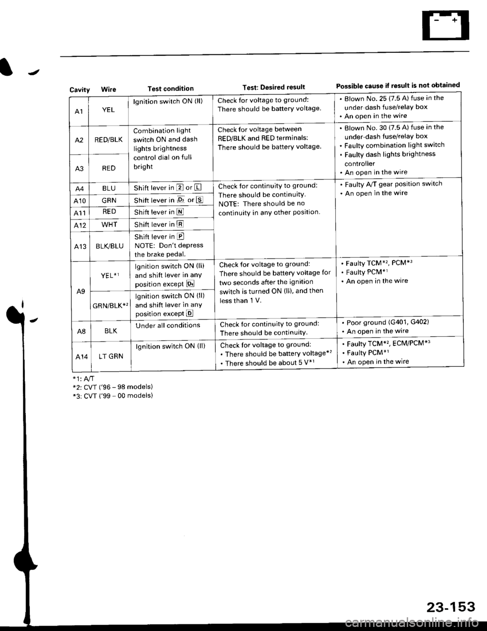
Test conditionTest: Desired resultPossible cause it result is not obtainedCavity
AIYEL
lgnition switch ON (ll)Check for voltage to ground:
There should be banerY voltage.
. Blown No.25 (7.5 A) fuse in the
under dash fuse/relay box
. An open in the wire
A2RED/BLK
Combination light
switch ON and dash
lights brightness
control dial on full
bright
Check for voltage between
RED/BLK and RED terminals:
There should be batterY voltage.
Blown No. 30 {7.5 A) fuse in the
under-dash tuse/relay box
Faulty combination light switch
Faulty dash lights brightness
controller
An open in the wireA3RED
BLUShift lever in P or ICheck for continuity to ground:
There should be continuitY
NOTE: There should be no
continuity in anY other Position.
. Faulty A/T gear Position switch
. An open in the wire
A10GRNShift lever in E or E
A11REDShift lever in E
412WHTShift lever in E
A13BLK/BLU
Shift lever in E
NOTE: Don't depress
the brake pedal.
A9
YEL+ ]lgnition switch ON (ll)
and shift lever in any
position except Pi
Check for voltage to ground:
There should be battery voltage for
two seconds after the ignition
switch is turned ON (ll), and then
less than 'l V.
Faulty TCM*'�, PCM*3
Faulty PCM*r
An open in the wire
GRN/err*'
lgnition switch ON {ll)
and shift lever in anY
position except E
A8BLKUnder all conditionsCheck for continuitv to ground:
There should be continuitY.
. Poor ground (G401, G402)
. An open in the wire
414LT GRN
lgnition switch ON (ll)Check for voltage to ground:
. There should be baftery voltage*'�
. There should be about 5 V*r
Faulty TCM*'�, ECM/PCM*'
Faulty PCM*1
An open in the wire
*2: CVT ('96 - 98 models)*3r CVT ('99 - 00 modelsl
23-153
Page 1627 of 2189
(A,4)
A,T GEARPosrfloN swlrcH _ _(Closed h posilon l?l ot [!l )
BLU/BLK -> [h'#f- |COMEINATIONLIGHT SWITCH
V
IREO/GRN
UNDEF.DASH FUSEi RELAY BOX
a
E
YEL
I
A iEi,I,B"'T
vll".i,l
| ,rr.nrorro .orrro, ,*,,
tt-
t(
rffi
|
BEMI\DEB crqcurl
lm
| /t I
tffinEoTsru REDTBLU BLIJ/RED clnculr
-neoieru | ,,-,r.0 J
l, "ulTo
/fP /Itr\
YVI onrveqs I or rtor
l3fifl&''' l5frl'.'
l (3'&T' 8iytr") l
(3&Y fiti'fJ"fl )
BLK BLK
TT
c552 G401
I
. BRAKE FLUIDLEVEL SWITCH. PARKING ERAKEswrTcH (usA)
' CEILING LIGHT. KEYLESS RECE VER CIRCUIT(ln lhe audio unil")
..aorr,rro Y
A
Iu$ut,""'
I3fif'�3#3trr,)-::
DRIVER'SDOOFswtTcHfolosed : Door open )(Open :Doordosed/
STARTERCUT FELAY
a
-
GFNi RED
23-157
Page 1630 of 2189

Integrated Gontrol Unit
Input Test (cont'dl
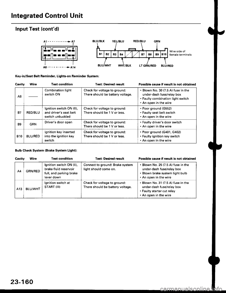
A8--------.--all
Key-in/Seat Belt R€mind€r, Lights-on Reminder Systom:
Cavity WireTest condhion
Bulb Check System (Brako System Light):
Cavity WireTest condilion
Tost: D€sirod r€guh
T6st: Dosirad result
Possible cause if result is not obtained
Possibls cause if rasuft b not obtainod
A8
Combination light
switch ON
Check for voltage to ground;
There should be battery voltage.
Blown No.30 (7.5 A)fuse in the
under-dash fuse/relay box
Faulty combination light switch
An open in the wire
B7RED/BLU
lgnition switch ON (ll),
and driver's seat belt
switch unbuckled
Check for voltage to ground:
There should be 1 V or less.
Poor ground (G552)
Faulty seat belt switch
An open in the wire
B9GRNDriver's door openCheck for voltage to ground:
There should be 1 V or less.
. Faulty driver's door switch. An open in the wire
Bl0BLU/RED
lgnition key inserted
into the ignition key
switch
Check for voltage to ground:
There should be 1 V or less.
Poor ground (G401. G402)
Faulty ignition key switch
An open in the wire
A4GRN/RED
lgnition switch ON {ll),
brake fluid reservoir
full, and parking brake
tever oown
Connect to ground: Brake system
light should come on.
Blown No.25 (7.5 Alfuse in the
under-dash fuse/relay box
Blown brake system light bulb
An open in the wire
A13BLUA/1r'HT
lgnition switch at
START (III)Check for voltage to ground:
There should be battery voltage.
Blown No.31 (7.5 A) fuse in the
under-dash fuse/relay box
Faulty starter cut relay
An open in the wire
23-160
Page 1631 of 2189
Lighting System
Component Location Index
DAYTIME RUNNING LIGHTSRESISTOR {Canada)Test, page 23 167
DAYTIME RUNNING LIGHTS
CONTROL UNIT (Canadal
Input Test, Page 23 166*HEADLIGHT
Adiustment, page 23-168Replacement, page 23-167
SIGNAL LIGHTReplacement, page 23 167
HIGH MOUNT BRAKE LIGHT
Replacement, page 23-177
LICENSE PLATE LIGHTS
Replacement, Page 23'174
INNER TAILLIGHTReplacement, page 23-169
OUTER TAILLIGHTReplacement, page 23 I69
*: Headlight and front parking/front turn signal light cannot be separated.(cont'd)
23-161
Page 1636 of 2189

Lighting System
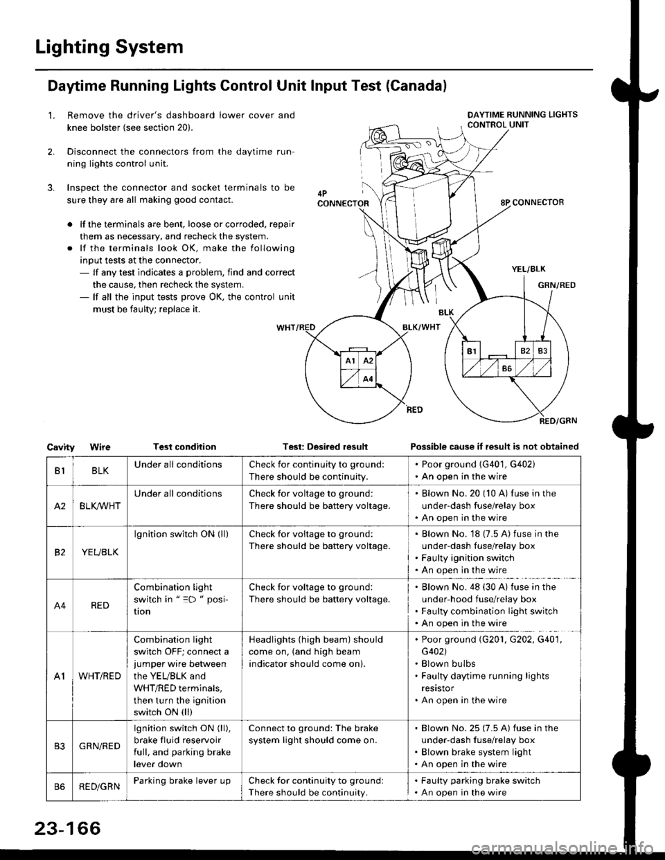
Daytime Running Lights Control Unit Input Test (Canadal
2.
3.
LRemove the driver's dashboard lower cover and
knee bolster (see section 20).
Disconnect the connectors from the daytime run-
ning lights control unit.
Inspect the connector and socket terminals to be
sure they are all making good contact.
lf the terminals are bent, loose or corroded. repair
them as necessary, and recheck the system.
lf the terminals look OK, make the following
input tests at the connector,- lf any test indicates a problem, find and correct
the cause, then recheck the system.- lf all the input tests prove OK, the control unit
must be faulty; replace it.
CavityWireTGst conditionTest: Desired resultPossible cause it result is not obtained
BLKU nderall conditionsCheck for continuity to g.ound:
There should be continuity.
. Poor ground (G401, G402). An open in the wire
A2BLK /VHT
Underall conditionsCheck for voltage to ground:
There should be battery voltage.
Blown No.20 (10 A) fuse in the
under-dash fuse/relay box
An open in the wire
etYEUBLK
lgnition switch ON (ll)Check for voitage to ground:
There should be battery voltage.
Blown No. 18 {7.5 A) fuse in the
under-dash luse/relay box
Faulty ignition switch
An open in the wire
A4RED
Combination light
switch in " =D " posi-
UOn
Check for voltage to ground:
There should be battery voltage.
Blown No. 48 (30 A) tuse in the
under-hood fuse/relay box
Faulty combination light switch
An open in the wire
A1WHT/RED
Combination light
switch OFF; connect ajumper wire between
the YEUBLK and
WHT/RED terminals,
then turn the ignition
switch ON (ll)
Headlights (high beam) should
come on, (and high beam
indicator should come on).
. Poor ground (G201, G202, G40'1,
G402). Blown bulbs. Faulty daytime running lights
resrstor. An open in the wire
GRN/RED
lgnition switch ON (ll),
brake fluid reservoir
full, and parking brake
lever down
Connect to ground: The brake
system light should come on.
Blown No.25 (7.5 A) fuse in the
under-dash f use/relay box
Blown brake system light
An open in the wire
REDiGRNParking brake lever LrpCheck for continuity to groundl
There should be continuity.
. Faulty parking brake switch. An open in the wire
23-166
Page 1641 of 2189
Taillights
Replacement (Except'99 - 00 Sedanl
NOTE:
. Inspect the gasket; replace it il it is distorted or stays
compressed.
. After installing the taillights, run water over them to
make sure they do not leak.
Outer Taillights ('96 - 00 models, except'99 - 00 Sedan):
1. Open the trunk lid/hatch.
2. Disconnect the 4P or 6P connector trom the outer
taillight.
3. Remove the four mounting nuts, then pull out the
outer taillight.
l-
Hatchback:
BRAKE/TAILLIGHT: 2115W
TURN SIGNAL LIGHT: 21 W
BACK-UP LIGHT: 21 W
4P or 6P CONNECTOR
BRAKE/TAILLIGHT: 2115W
TURN SIGNAL LIGHT: 21 W
BRAKEiTAILLIGHT: 2115 W
BACK-UP LIGHT: 21 W
Inner Taillights (Coupe'96 - 00 models/Sedan'96 - 98
models):
1. Open the trunk lid, then remove the access panel.
2. Disconnect the 4P connector from the inner taillight.
3. Remove the four [three] mounting nuts, then pull
out the inner taillight.
I l: Sedan
Coupei
INNER TAILLIGHT
Sedan:
INNER TAILLIGHT
4P CONNECTOB
Page 1642 of 2189
Taillights
Replacement ('99 - 00 Sedanl
NOTE:
. Inspect the gasket; replace it if it is distorted or stays
compressed.
. After installing the taillights, run water over them to
make sure they do not leak.
Outer Taillights:
1. Open the trunk lid/hatch.
2. Disconnect the 4P and 2P connector trom the outer
taillight.
3. Remove the four mounting nuts, then pull out the
outer taillight.
TAILLIG}fi
4P CONNECTOR
BRAKE/TAILLIGHT: 2115W
TURN SIGNAL LIGHT: 21 W
r*i/et./
23-172
Inner Taillights:
'1. Open the trunk lid, then remove the access panel.
2. Disconnect the 3P and 2P connector from the inner
taillight.
3. Remove the three mounting nuts, then pull out the
inner taillight.
[ ]: Sedan
BRAKE/TAILLIGHT: 2r15 W
BACK.UP LIGHT: 21 W
3P CONNECTOR