Page 915 of 2189

Symptom-to-Component Chart
Electrical System -'96 - 98 Models
*: The DTC in parentheses is the code @ indicator light indicates when the Data Link Connector is connected to the HondaPGM Tester.
DTC*O Indicator
LightMILDetection ltemPage
P1790
(3)BlinksONThrottle position sensor14-242
P179'l
(4)BlinksONVehicle speed sensor14-243
P1705
(5)BlinksONAy'T gear position switch (short to groundl't 4-244
P1706
(6)OFFONA/T gear position switch {open)14-246
P0725
(11)BlinksONlgnition coil14-248
P1793
112lBlinksONManifold absolute pressure sensor14-249
P 1870(30)BlinksONShift control linear solenoid14-250
P'1873
(311BlinksONPH-PL control linear solenoid14-25'l
P1879(32)BlinksONStart clutch control linear sotenoid14-252
P1882BlinksONInhibitor solenoid14-253
P1885
(34)BlinksONDrive pulley speed sensor1l-Zb4
P1886(35)BlinksONDriven pulley speed sensor14-255
P1888
(36)BlinksONSecondary gear shaft speed sensor14-256
T to55
(37)BlinksONECM or TCM14-257
P1890
l42lBlinksONShift control system14-259
P1891
(43)BlinksONStart clutch control svstem14-260
14-23a
Page 917 of 2189
Symptom-to-Com ponent Chart
Electrical System -'99 - 00 Models
r: The DTc in parentheses is the code E indicator light indicates when the Data Link connector is connected to the HondaPGM Tester.
DTCTE Indicatot
LighrMILDetostion ltemPage
P1705
(5)ElinksONA,/T gear position switch (short to grouno,14-265
P1706
(6)OFFONA"/T gear position switch (open)14-26€
P1870
(30)BlinksONShift control linear solenoid14-271
P1873
(31)BlinksONPH-PL control linear solenoid14-213
P1879
t32lBlinksONStan clutch control linear solenoid
Inhibitor solenoid
14-215
P1882(33)BlinksON't 4-277
P1885
(34)BlinksONDrive pulley speed sensol't 4-279
P1886
(35)BlinksONDriven pulley speed sensor14-281
P1888
(36)BlinksONSecondary gear shaft speed sensor
Shift control system
14-283
P1890
\421BlinksON14-245
P1891
(43)BlinksONStart clutch control system14-286
14-240
Page 927 of 2189

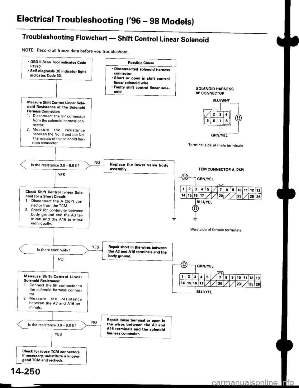
Electrical Troubleshooting (,96 - 9g Modelsl
Troubleshooting Flowchart - Shift Control Linear Solenoid
Possible Cause
' Disconnected 3olenoid h.rn€isconnoctor. Short or open in 3hift controllinear solenoid wire. Faulty shift control linear sole-noidSOLENOID HARNESS8P CONNECTOR
Terminal stde of male terminals
Wire side of female terminals
8LU/YEL
NOTE: Record all freeze data before you troubleshoot.
. OBD ll Scan Toot indicates CodeP1870.. Selt-dirgnosis [d indic.tor tightindicatos Code 30.
Measure Shift Control Linoar Sole-noid Resistance at the SolenoidHarness Connector:1. Disconnect the 8p connectorfrom the solenoid harness connector.2, Measu re the resistancebetlveen the No. 3 and the No.7 terminals ofthe solenoid haFness connector.
ls the resistance 3.8 - 6.8 O?
Check Shift Controt Linear Sote-noid for a Short Circuit:1. Disconnect the A (26p) con,nector from the TCM.2. Check for continuity betweenbody ground and the A3 terminal and the A16 terminalindividually.
Repair shon in tho wire6 betweonthe A3 and A16 termin.ts lnd thobody ground.
Measure Shitt Control Line.rSolenoid Resistance:1. Connect the 8P connector tothe solenoid harness connec,tor.2, Meas u re the resistancebetween the 43 and A16 ter-
Repair loose terminal oa open inthe wires between the 43 andA16 terminal3 and the solenoidharness connector.
ls the resistance 3.8 6.8 O?
Chock for loose TCM connectorc.ll necessary, substitute a known-good TCM and recheck.
BLU/WHT
GRN/YEL
TCM CONNECTOR A I26PI
GRN/YEL
ll 12l:
IriGlx
1578910111213
172t)232526
14-250
Page 928 of 2189

Troub|eshootingF|owchart_PH-PLControJLinearSo|enoid
NOTE| Record all treeze data before you troubleshoot
Possible cause
' Disconnected solenoid harness
connectof. Short or oPen in PH_PL control
linear solenoid wire. Faulty PH-PL control linear sole_
noidSOLENOIO HARNESS8P CONNECTOR
GRN/WHT
Terminal side of male termlnals
Wire side ol female terminals
. OBD ll Scan Tool indicates Codo
P1873.. sef-diagnosis E indicalor light
indicat6 Code 31.
Measure PH-PL Control Linear
Solenoid Resistance at the Sole_
noid Hatness Connectot:1. Disconnect the 8P connector
from the solenoid harness con-
nector,2. Measure the resistance
between the No 2 and the No.
6 terminals ofthe solenoid har
ness connector'
ls the resistance 3.8 - 6.8 0?
Check PH-PL Control Lineer
Solenoid for a Short Circuit:
1. Disconnect the A 126P) con-
nector lrom the TCM
2. Check for continuity between
body ground and the A2 ter
minal and the A15 terminal
individually.
Repair short in th€ wires
between the A2 and A15 lermi_
nals and the body glound.
Measute PH-PL Control Linear
Solenoid Resi3tance:1. Connect the 8P connector to
the solenoid harness connec-
tor,2, Meas u re the reslslance
between the ,q2 and A15 ter_
Rep.il loose tetminal or oPen in
th6 wires betwccn the A2 and
A15 lerminals and the solenoid
harness conn€ctol.
lsthe resistance 3.8-6 8 O?
Check for loose TCM connactors
lf neceasery, Substitute a known-good TCM and rechock.
PNK/BLK
TCM CONNECTOR A (26P)
oPNK/BLK
I234578I10l11213
11't5161720/,,/232526
IGRN/wHr
o
*r}l
t'T,
E[
PNK/8LK
3a5I910111213
1620232526
GRN/WHT
14-251
Page 929 of 2189

Electrical Troubleshooting ('96 - gg Modelsl
Troubleshooting Flowchart - start clutch control Linear solenoid
NOTE: Record all freeze data before you t.oubleshoot.
Po$iblo C.u.o
' Di3aonnoctod solanoid harncatconnactol. Short or opon in start clutchcontrol linoar tolanoid wira. Faulty ttart clutch control lino.rsolanoid
SOLENOID HARNESS8P CONNECTOR
Terminal side of male terminals
Wire side of female terminals
. OBO ll Scan Tool indicatG CodeP1879.. Self-dilgno.is E indicator lightindiclt$ Code 32.
Me.suro Sta.t Clutch ControlLinear Solenoid Rosirtrnco st th.Solenoid Hrrn6rs Connecto.:1. Disconnect the 8P connectorfrom the solenoid harness con-nector.2, Measure the resistancebetween the No. 4 and the No.8 terminals otthe solenoid har-ness connectot.
ls the resistance 3.8 - 6.8 0?
Chock Start Clutch Control Lin-oar Solenoid tor a Short Circuit:1. Disconnect the A (26p) con,nector from the TcM.2. Check lor continuity betweenbody ground and the A1 ter-rninal and lhe Al il terminalindividually.
Raprir 3hort in tha wira3b.ftvcen tho A1 .nd Atil t .mi.n.l. .nd thr body ground.
Measure Stan Clutch Cont.olLineer Solenoid F6aist.ncei1. Connect the 8P connector tothe solenoid harness connec-tor.2. Meas u re the resistancebetween the 41 and Al4 ter-minals,
Rcplir loose tcrminal or oDcn inthG wiras b.tween the Al rndAla torminal3 rnd tha 3olanoidhamaas connactor.
ls the resistance 3.8- 6.8 O?
Check for loose TCM connecto.s.lf necessary, substitute a known-good TCM and iecheck.
YEL
PNK/BLU
TCM CONNECTOR A I26P}
-{r-
E
PNK/BLU
23a51I910ll1213
a15t61'20a252G
YEL
14-252
Page 930 of 2189

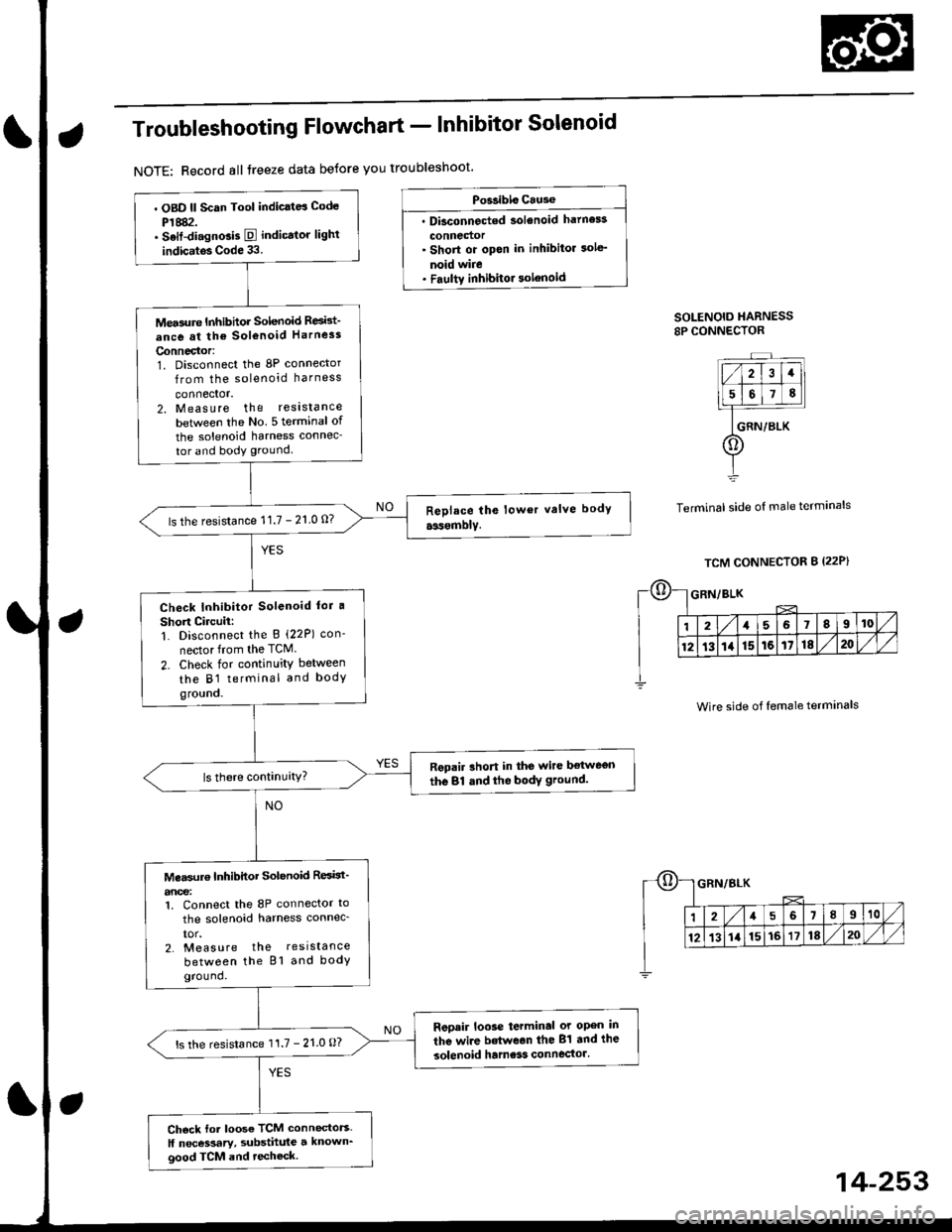
Troubleshooting Flowchart - Inhibitor Solenoid
NOTE: Record all treeze data betore you troubleshoot
Po$ibls Cause
. Dbconnected solenoid hatness
connedor' Short or opon in inhibitor sole'
noid wire. Faultv inhibitor solenoid
SOLENOID HARNESS8P CONNECTOR
Terminal side of male terminals
. OBD ll Scan Tool indic.td Code
P1882.. Selt-di.gnGis E indicator lighl
indic.tos Code 33.
Mea3ure Inhibhor Solenoid Resid-
ance at the sol€noid Harness
Connector:1. Disconnect the 8P connector
from the solenoid harness
connector.2. Measure the reslstance
betlveen the No 5 terminal of
the solenoid harness connec-
tor and body ground.
ls the resistance 11.7 - 21 0 0?
Check Inhibitor Solenoid lor a
Short Circuii:1. Disconnect the B (22P) con-
nector from the TCM.
2. Check for continuity between
the B1 terminal and bodygro!no.
Repair rhort in the wire ltetwegn
the 81 dnd the bodY ground.
Mea$rr€ Inhibitor Solenoid ResBt'
anoe:1. Connect the 8P connector to
the solenoid harness connec_
IOr.2. Measure the resistance
between the Bl and bodyground.
Reoair loose terminal or open in
the wire betwean the 81 and the
solenoid hame3s connector'ls the resistance 11.7 - 21.0 O?
Ch6ck for loose TCM connectors.
ll necessary, substhule a known_good TCM and techeck.
Wire side of female terminals
14-253
Page 937 of 2189

Electrical Troubleshooting ('96 - 98 Models)
Troubleshooting Flowchart - Start Clutch Control System
NOTE: Record all freeze data before you troubleshoot.
Po$ible Ceuaa
Frulty start clutch cont.ol 3ys-tem
14-260
OBO ll Scan Tool indic.le3 Cod6P1891.Solt-diagnosis E indicator lightindicates Code (1.
Check for Another Codo:Check whether the @ indicatorlight indicates another code.
Poiform tho TroublcahootlngFlowchrrt lor the indicat.dCode(sl.
ls the E indicator light indi-cate another code?
Test Strrt Clutch Oper.tion:1. Turn the ignition switch OFF.2. Disconnect the 8P connectorfrom the solenoid harness con,nector.3. Start the engine, and shift toE position.4. Check whether the vehiclemoves.
Rcplaca th. strrt dudt r$amt ly.
Check Creeping Spe€d:1. Turn the ignition switch OFF.2. Reconnect the 8P connector tothe solenoid harness connec-tor,3. Start the engin6, and shift toE position.4. Check whether the vehiclecreeps, and chock the creep-Ing speed.
Does the vehicle move and isthe creeping speed approx.3mph (5 km/h)?
To page 14-261
E
Page 948 of 2189

JTroubleshooting Flowchart - Shift Control Linear Solenoid
NOTE: Record all freeze data before you troubleshoot
Possiblc Cause
. Disconn€cted solenoid harnos3
connectol. Short or oDen in shilt controllinetr solonoid wiro. Faulty shift control linear sole_
noid. Op€n in VB SOL wite. ODen in PG'l and PG2 wires or
poor ground {G10'l)
f,
wire side ot female terminals
LG1 IBRN/BLKILG2IBRN/BLK)
{cont'd)
14-271
PCM CONNECTORS
B(25P) - Dll6P)
.OBD ll Scan Tool indicatos
Code P1870.. Solf-diagnosis E indic.lor light
indic.t€s Code 30.
M6a3ure VB SOL voltage:1. Turn the ignition switch OFF.
2. Disconnect the B 125P) and D(16P) connectors from the
PCM,3. Turn the ignition switch ON (ll).
4. Measure the voltage between
the D5 and 820 or 822 terminals.
Repair open or shod in the wire
between the D5 terminal and the
under-dash tuso/telay box.
Check the Ground Circuitl1. Turn the ignition switch OFF.2. Check lor continuity between
the terminafs 82 and 822 and
between terminals 810 and
820.
Repair open in the wi.e betwoen
the termin.ls 82, B10, B20, and
822 and G101. Repair Poolground (G101).
LG1 IBRN/BLKI
PCM CONNECTOR B PsPI
PG,I IBLK)
10 page 14-272
a