1999 HONDA CIVIC fuse relay box
[x] Cancel search: fuse relay boxPage 1804 of 2189
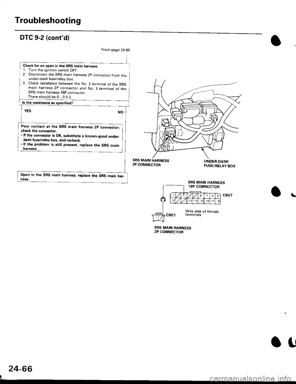
Troubleshooting
DTC 9-2 (cont'dl
2- Disconnect the SRS rnain harness 2p connector lrom theunder-dash fuse/relay box.3- Check resistance between the No. 2 terminal of the SRSmain harness 2P connecior and No. 3 terminal of theSFS main harness 18P connector_
Poor contact at the SRS main ha.ness 2p connector;check the connecto... lf the connector is Ol(, sub3titute a known-good under-dash tuse/r€lay box, and recheck.'lt tho problem is still present, replece the SRS main
Open in the SBS main harness; replace the SRS main har_ness,
SRS MAIN HARNESS2P CONNECTOR
24-66
I
\
From page 24-65
Chock tor an open in th€ SRS main hern€ss:1. Turn the ignition switch OFF.
There should be 0 0.5 0
SRS MAIN
SRS MAIN HARNESS18P CONNECTOR
o!
Page 1817 of 2189

Contents
How to Use This Manual ICircuit Schematics (see Circuit Index)Fuse/Relaylnformation 6Ground-to-Componentslndex 6-6ComponentLocationPhotooraohs 201Conriector Views 202
Circuit Index
Accessory power socket 155Air conditionerAir delivery'96198 models 61'99-'00 models 61-2Blower controls'96198 models 60'99100 models 60-1Compressor controls 62Fans 63Anti-lock brake system (ABS) 44A/T gear position indicatorCVT 89All except CVT 89-1Automatic transmission controlsAll '96-'98 models except CVT and GX 39All '99100 models except CVT 39-8All GX models 39-8'96-'�98 CVT 39-4'99100 cw 39-12Back-up lightsCoupe and Sedan 110Hatchback l'10-1Brake lightsAll Coupes and'96-'98 Sedans 110-15'99-'00 Sedans 110-16Hatchback 110-17Brake system indicator light'96198 models 7'1'99100 models 71-1Ceiling light 114-3Charging system 22Condenser fan 63Console lights 114Cruise control 34Dash lights 114Daytime running lights 110- 13Engine coolant temperature gauge 81-1Fog lights 110-10Front parking lights 110-2Fuel gauge 81-1Fuse/relay boxUnder-dash 6Under-hood 6-4Underhood ABS 6-3Gauges 81Ground distribution 14Ground-to-Componentslndex 6-6Hazard warning lightsAll except '99100 Sedans 110-6'99100 Sedans 110-8Headlights 110-12Headlight switch 100Heater - See Air ConditionerHorn'96197 models 40'98 model 40-1'99100 models 40-2lgnition key reminder 73lgnition systemAll '96198 models except Dl685 20All '99100 models except D16Y5 with Mn 2O-2All D1685 engines 20-2'99-'00 D 16Y5 with M/T 20
lndicators 80Integrated control unit 70lnterlock systemAll except'96J98 CVT 138'96198CVT 138-1License plate lightsAll Coupes and '96-'98 Sedans I l0-3'99100 Sedans 1 10-4Hatchback 110-5Low fuel indicator light 74Moonrool'96197 models |22'98-'00 models 122-1Odometer 81Oil pressure indicator light 80-3Power distributionBattery to ignition switch, fuses, and relaysFuses to relays and components 10-2Power door locksAll models without keyless entry 130'96-'98 models with keyless entry 130-2'99100 models with keyless entry 130-12Power mirrorsWithout detogger 141With defogger '141-2
Power windows 120Programmed fuel injection system (PGNr-Fl)All '96-98 models except D1685 23All '99-'00 models except D16Y5with M/T and D1685 24All D1685 engines 25'99100 D16Y5 with M/T 23Radiator fan 63Rear window defogger'96-,98 models 64'99100 models 64-1Seat belt reminder 73Security system'96.'98 USA HX, LX, EX 133'96-'98 Canada EX, Si 133'99TOO USA HX, LX, EX, DX.V Si 133-4'99100 Canada EX, Si 133-4All CX and DX models 133-8Speedometer 81Starting systemA./T (All except Dl685) 21A"/r (D16Bs) 21-1Manualtransmission 21-2Slereo sound system 150Supplemental rastraint system (SRS) 47Tachometer 81TailliqhtsAllboupes and'96-'98 Sedans 110-3'99100 Sedans 1 10-4Hatchback 110-5Trunk light 114-3Turn signal lightsAll except'99100 Sedans 110-6'99-'00 Sedans 1 10-8Vehicle speed sensor (VSS) 33Wiper/washerFront 91Rear 92
10
Page 1819 of 2189
How To Use This Manual
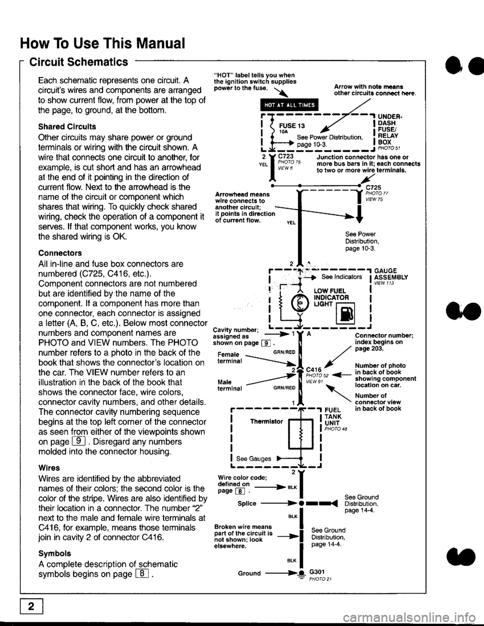
Circuit Schematics
oa
Each schematic represents one circult. A
circuit's wires and components are arranged
to show current flow, from power at the top of
the page, to ground, at the bottom.
Shared Circuits
Other circuits may share power or ground
terminals or wiring with the circuit shown. A
wire that connects one circuit to another, for
example, is cut short and has an arrowhead
at the end of it pointing in the direction of
current flow. Nelit to the anowhead is the
name o{ the circuil or comoonent which
shares that wiring. To quickly check shared
wiring, check the operation of a component it
serves. lf that component works, you know
the shared wiring is OK.
Connectors
All in-line and fuse box connectors are
numbered (C725, C416, etc.).
Component connectors are not numbered
but are identiJied by the name of the
component. lf a componenl has more than
one connector, each connector is assigned
a letter (A, B, C, etc.). Below most connector
numbers and comDonent names are
PHOTO and VIEW numbers. The PHOTO
number refers to a Dhoto in the back of the
book that shows lhe conneclor's location on
the car. The VIEW number refers to an
illustration in the back of the book that
shows the connector face, wire colors,
connector cavity numbers, and other details.
The connector cavity numbering sequence
begins at the top left corner oJ the connector
as seen from either of the viewooints shown
on page ffl . Disregard any numbers
molded into the connector housino.
Wires
Wires are identilied by the abbreviated
names of their colors; the second color rs the
color of the stripe. Wires are also identified by
their location in a connector. The number '2"
next to the male and female wire terminals at
C416, for example, means those terminals
join in cavity 2 of connector C416.
Symbols
A complete description of schematic
symbols begins on page | 8
"HOT" label tells you whenthe ignition switch suppliespower to the fuse. \
Artowhead meanswire connects toanother circuit;
Arrow with note rErngother circuils conncct h€re.
it .a
llu":: ^,{ ii t See Power Distribution, .I t----t oaqe tO-3. IL*--:--------J2 Y C723 Junction connectorYEL I Pao'o'8 more bus bars in it;
I - " " to two or more wire
l,/
-t>?
See PowerDistribution,page 10-3.
UNDER.DASHFUSE/RELAYBOX
has one oleach connactgterminala.
it ooints in directionof current flow.
TheImletor
t_I
Cavity number; L ---
Jiili'iJi!--' -----> '
shoin on page S .
Maleterminal
L?*?l?,-
"'"'I
c725
vlEUt/ 75
Connector number;index begins onpage 203.
Number ot photoin back ol bookshowing componentlocation on cat.
Number ofconneclor viewin back of book
7
GBN/FEO
See Ground
Soe Indicators I ASSEMBLY
:-------J
LOW FUELINDICATOFLIGHT r-l
EI
A
"o'r"/PHOTO 52 <-
\
FUELTANKUNIT
Splice ---------) O rr
".* I Page 14'4'
IBroken wire means | --^ -
iar";J.'It,;,rJ;ii; -----i Bffi,Bili*l
elsewhere. I 0a0e tn-a
IBrK Icround --->lL c301: ptioro 21
Page 1821 of 2189
How To Use This Manual
Power Distribution Schematics (cont'd)
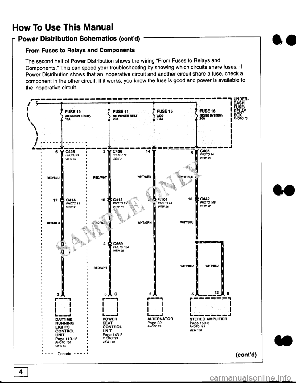
From Fuses to Relays and Components
The second half of Power Distribution shows the wiring "From Fuses to Relays and
Components." This can speed your troubleshooting by showing which circuits share luses. lf
Power Distribution shows thal an inoperative circuit and another circuit share a fuse, check a
component in the other circuit. lf it works, you know the fuse is good and power is available to
the inoDerative circuit.
oa
UNDER.DASHFUSE/RELAYBOXI i *. to i ru..'.' l * tt I tust tt
){nuo$rouc}rr) }g*"""' }tS }ff***,
\
I
,
I-- - ----\&- -----J-------ir
9,s9:,.,
,.,'li"'"rr' ' 'rll$vryglu
:
]:l. ,' "'':r.,
,:ti. .:1,,.,
*_lu*'.
'71ffi"�
- -t**,-
vtEw &
04 18 g C442
2A
tl
12 .L e
tl
ALTENNATORPaoe 22PHdro 29
ll
tlL------JSTEREO AMPLIFIERPaoe 150-3PHdfo 1s3vtEw 106
121
'f,"c;93,. : '� f,t'ffi
lv'Ew6o ! 1,.",
l:lN'll
^.o,r.u I i ".o,*", I
l:t
l,l
u*,.11,2", i "l9*',g
11""" : l*'-
l:lnEDisLu
|
; . ED,w' (
I'lP:ll
! " : .1".,9t3
q - '
I v'Ew3e
h;ll
l:ll
I : FED^rir{r
i
l:i
tii
,.L i slc
r--1 : r--1
tt:ll
ltlllt--J ' l--JDAYTIME : POWERRUNNING ; SEATLIGHTS . CONTROLCONTROL . UNITUNIT ' Paoe 143-2paoe 1to-j2 t PHdro t2.PHdTo 1so i wEw 110vtEw 65
- - -' Canada '_ _ _(cont'd)
Page 1825 of 2189
How To Use This Manual
Symbols
oo
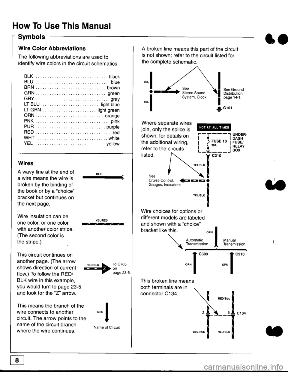
Wire Color Abbreviations
The following abbreviations are used to
identify wire colors in the circuit schematics:
BLK.... .........b|ack
BLU.... ......... blue
BRN.... ,....... brown
GRN.... ........ green
GRY.... ......,.. gray
LTBLU . .....lightbtue
LTGRN. ....lightgreen
ORN.... ....... orange
PNK .... .......,.. pink
PUR .... ........ purple
RED .... .......... red
WHT... .........white
YEL .... ........ yellow
A broken line means this part of the circuit
is not shown; refer to the circuit listed for
the complete schematic.
"ral
o
-.1
See GroundDistribution,page 141.
I G101
Where separate wires
join, only the splice is
shown; for details on
the additional wiring,
refer to the circuits
listed.ili::i
{[
UNDER-OASHFUSE/RELAYBOX
Wires
A wavy line at the end of
a wire means lhe wire is
broken by the binding of
the book or by a "choice"
bracket but continues on
the next page.
Wire insulation can be
one color, or one color
with another color stripe.
(The second color is
the stripe.)
This circuit continues on
another page. (The arrow
shows direction o{ current
flow.) To tollow the RED/
BLK wire in this example,
you would turn to page 23-5
and look for the "2" anow.
This means the branch of the
wire connects to another
circuit. The arrow Doints to the
name of the circuit branch
where the wire continues.
8LK-Cruise Control, €�aaaGauges, Indrcalors
!YEUsLK
Ttl
Wire choices for options or
different models are labeled
and shown with a "choice"
bracket like this.
This broken line means
both terminals are in
connector C134.
a.
+##l:i""lManuallransmission
ryil;::,
.""1
""'
"""1".'0
I
""^l
:-lName of Circuit
Page 1834 of 2189
![HONDA CIVIC 1999 6.G Workshop Manual Fuse/Relay Information
- Under-dash Fuse/Relay Box
Front View
c712(To moonroof wire harness)
. : Canadai : Not UsedO : C926 loprion (+B)l
@ : C927 loption (dash lights)]
O : C928 [Option (ACC]I
@ : C9 HONDA CIVIC 1999 6.G Workshop Manual Fuse/Relay Information
- Under-dash Fuse/Relay Box
Front View
c712(To moonroof wire harness)
. : Canadai : Not UsedO : C926 loprion (+B)l
@ : C927 loption (dash lights)]
O : C928 [Option (ACC]I
@ : C9](/manual-img/13/6068/w960_6068-1833.png)
Fuse/Relay Information
- Under-dash Fuse/Relay Box
Front View
c712(To moonroof wire harness)
. : Canadai : Not UsedO : C926 loprion (+B)l
@ : C927 loption (dash lights)]
O : C928 [Option (ACC]I
@ : C929 loption (lc2)l
Rear View
css2
c421(To main wire harness)
c801CI-o SRS main harness)
c501(To dashboard wire harness)
^ : Not used ('96-'97 models)
c913(To ignition switch)
INTEGRATEDCONTROL UNITCONNECTOR A
c419Oo main wire harness)
REAR WINDOWDEFOGGER RELAY
TURN SIGNAUHAZARD RELAY
c423(To main wire harness)
co
c422(To main wire harness)
POWERwtNDowRELAY
c551flo lloor wire harness)c439 f96.'97 MODELSand ALL GX MOOELS)(To main wire harness)
T1 T-t T"l T"t r-r r-'l T1 F n r-l r-l r'123 24 25 26 27 28 29 30 31 32 33I-J I.J I.J IJ IJ IJ LJ IJ IJ I.J I.J I-I
r"1 r-t r-t T-l r"l r-r Fl r:1 n rJ n -12 13 14 t5 16 17 t8 19 2A 2t 22LI I.J L! LI tJ LJ (J LI IJ IJ T-I I.J
n r:l rj.l |-l T"l Tl r:t n r-l |;.l r-r r-l1 2 3 4 5 6 7 I 9 10 11LI LI IJ LJ LJ I,J T-I I.J TJ IJ I.-I tJ
c420(To main wire harness)
6
(To floor wire harness)
Page 1836 of 2189
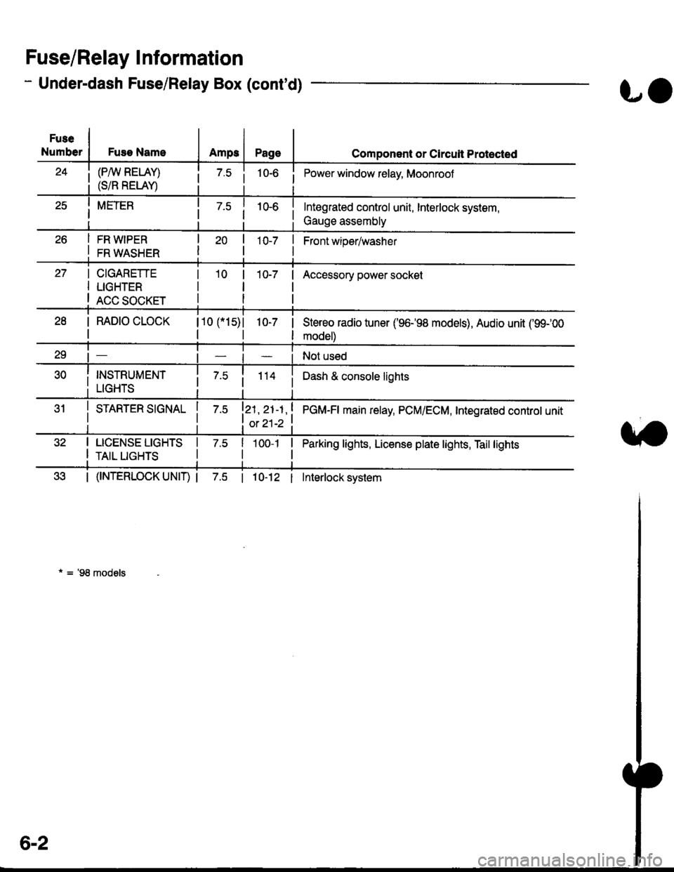
- Under-dash Fuse/Relay Box (cont'd)
Fuse/Relay I nformation
Fuse
NumberFuse NameAmps
(P/W RELAY)
(S/R RELAY)
FR WIPER
FR WASHER
LO
Page
10-7 |
I
Component or Clrcuit Protected
i Power window relay, Moonrool
Front wioer/washer
CIGARETTE
LIGHTER
ACC SOCKET
10-7Accessory power socket
I RAD|O CLOCK
I
110 115)l
tl
1O-7 |
I
Stereo radio tuner ('96198 models), Audio unit ('99100
model)
Not used
i 7.5i 114 iDash & console lights
I srnnrensrorunl | 7.slzl , zt -t , ! eCU-n main retay, PCM/ECM, Integrated controt unit
I ot 21-2 t
I LICENSE LIGHTS I 7.5
I rerr uesls I
Parking lights, License plate lights, Tail lights| 1oo-1 |
tl
| (f NTERLOCK UNIT) | 7.5 | 10-12 I Interlock system
* = '98 models
6-2
Page 1837 of 2189
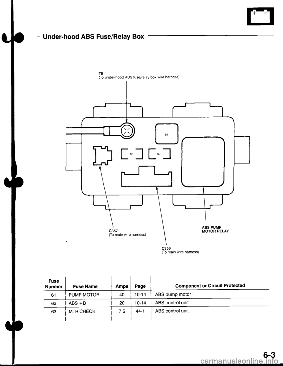
- Under-hood ABS Fuse/Relay Box
Fuse
Number
(To underhood ABS fuse/relay box w re harness)
ABS pump motor
| 10-14 I ABS control unit
i ABS control unit
component or circuit ProiectedFuse Name
PUMP MOTOR
I ABS +B
ABS PUMPMOTOR RELAY(To main wire harness)
(To rnain wlre harness)
I!,ITR CHECK
6.3