1999 HONDA CIVIC battery
[x] Cancel search: batteryPage 1714 of 2189
Cruise Gontrol
3.
1.
2.
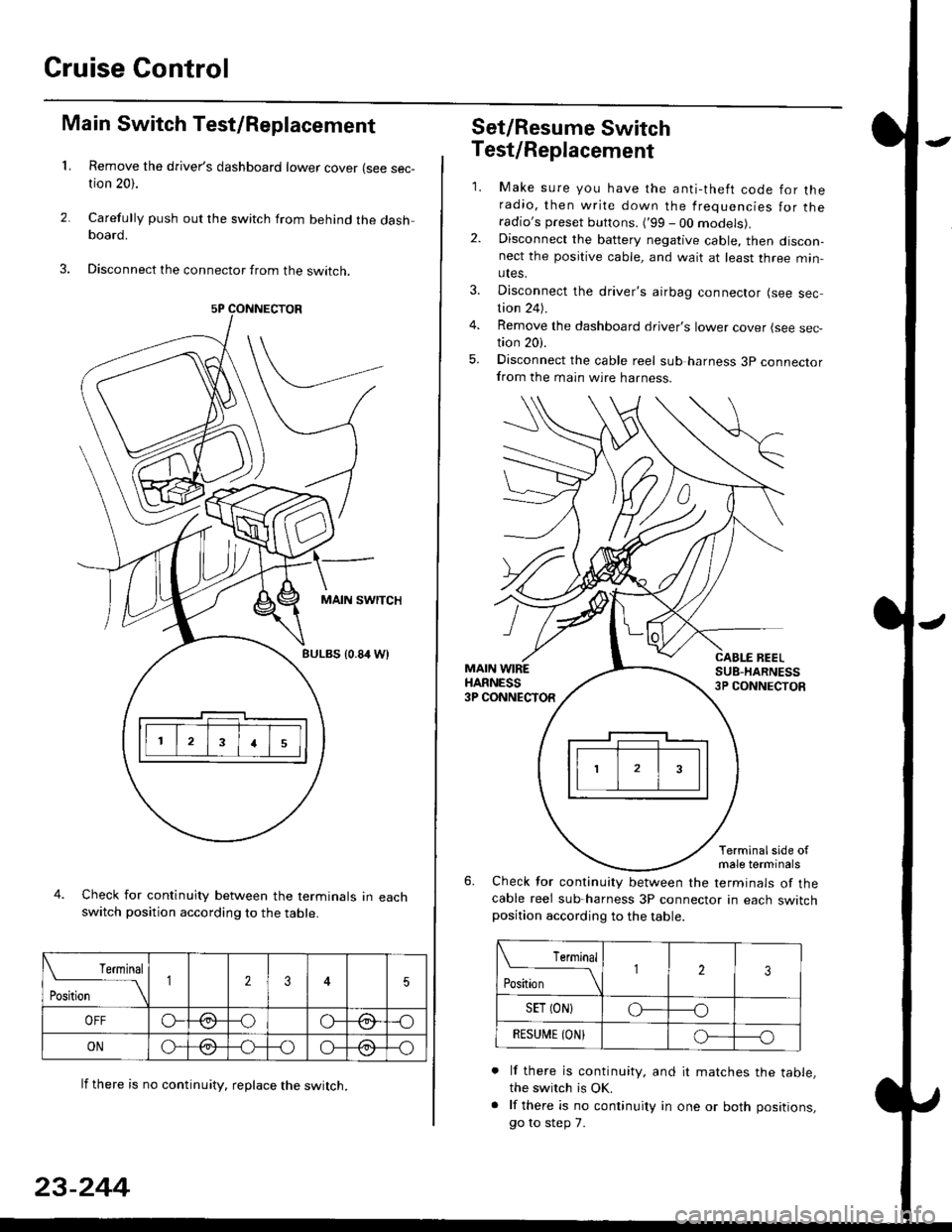
Main Switch Test/Replacement
Remove the driver's dashboard lower cover (see sec-tion 20).
Carefully push out the switch from behind the dashboard.
Disconnect the connector from the swtrcn.
MAIN SWITCH
BULBS {0.84 Wt
Check for continuity between the terminals in eachswitch position according to the table.
lf there is no continuity. reDlace the switch.
4.
Terminal
r**
--\235
OFFo--oGa\-o\:./\a/
ONo-/a-oo--o\:/\:/
23-244
Set/Resume Switch
5.
Test/Replacement
2.
1.
MAIN WIREHARNESS3P CONNECTOR
Make sure you have the anti-theft code for theradio, then write down the frequencies for theradio's preset buttons. ('99 - 00 models).Disconnect the battery negative cable, then discon-nect the positive cable, and wait at least three min-utes.
Disconnect the driver's airbag connector (see sec-tion 24).
Remove the dashboard driver's lower cover (see sec,tion 20).
Disconnect the cable reel sub harness 3p connectorfrom the main wire harness.
CABLE BEELSUB-HARNESS3P CONNECTOS
Terminalside ofmale terminals
Check for continuity between the terminals of thecable reel sub-harness 3P connector in each switchposition according to the table.
L Terminal
Position123
SET (ON}o----o
BESUi,|E IONIo-----o
lf there is continuity, and it matches the table,the switch is OK.
lf there is no continuity in one or both positions,
go to step 7.
Page 1715 of 2189
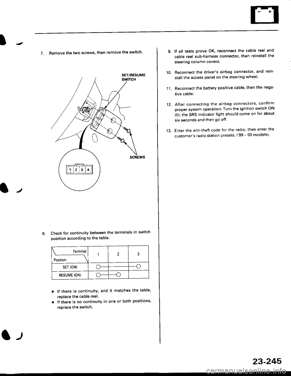
7. Remove th€ two screws, then remove the switch'
Check for continuity between the terminals in switch
position according to the table.
Terminal
t"-"t*
-\23
SET (ON)o--o
RESUI\4E {ON}o----o
lf there is continuity, and it matches the table,
replace the cable reel.
lf there is no continuity in one or both positions,
reDlace the switch.
8.
SET/NESUME
l-l
23-245
11.
q
10.
12.
lf all tests prove OK, reconnect the cable reel and
cable reel sub-harness connector, then reinstall the
steering column covers
Reconnect the driver's airbag connector. and rein-
stall the access panel on the steering wheel.
Reconnect the battery positive cable, then the nega-
tive cable.
After connecting the airbag connectors, confirm
proper system operation; Turn the ignition switch ON
(ll); the SRS indicator light should come on for about
six seconds and then go off.
Enter the anti-theft code for the radio, then enter the
customer's radio station presels {'99 -00 models)'
Page 1717 of 2189
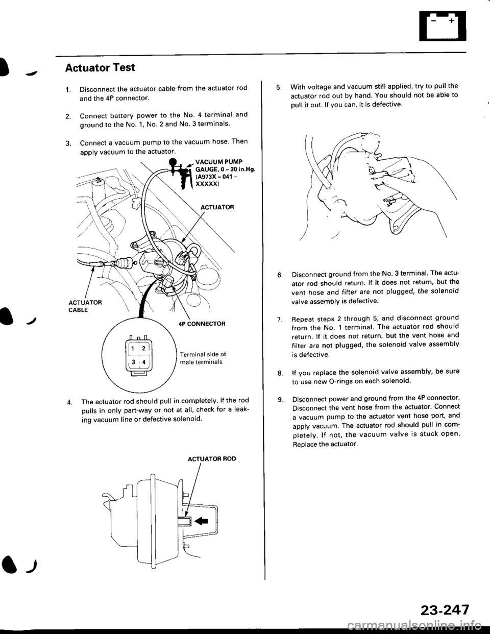
)Actuator Test
't.Disconnect the actuator cable from the actuator rod
and the 4P connector.
Connect battery power to the No 4 terminal and
ground to the No. 1, No. 2 and No. 3 terminals.
Connect a vacuum pump to the vacuum hose Then
apply vacuum to the actuator.
2.
VACUUM PUMPGAUGE,0 - 30 in.Hg.
{A973X - 041 -
xxxxxl
ACTUATOR
,lP CONNEcToR
Terminalside o{male termrnals
4. The actuator rod should pull in completely. lf the rod
pulls in only pan-way or not at all' check for a leak-
ing vacuum line or defective solenoid.
ACTUATOF ROD
l-t
23-247
5. With voltage and vacuum still applied, try to pull the
actuator rod out by hand. You should not be able to
oull it out. ll you can, it is defective
1.
Disconnect ground from the No.3 terminal. The actu-
ator rod should return lf it does not return, but the
vent hose and filter are not plugged, the solenoid
valve assembly is defective.
Repeat steps 2 through 5, and disconnect ground
from the No. 1 terminal. The actuator rod should
return. lI it does not return, but the vent hose and
filter are not plugged. the solenoid valve assembly
is defective.
It you replace the solenoid valve assembly, be sure
to use new O-rings on each solenoid.
Disconnect power and ground from the 4P connector.
Disconnect the vent hose from the actuator. Connect
a vacuum pump to the actuator vent hose port, and
apply vacuum. The actuator rod should pull in com-
pletely. lf not, the vacuum valve is stuck open.
Replace the actuator'
8.
Page 1721 of 2189
Power Door Locks
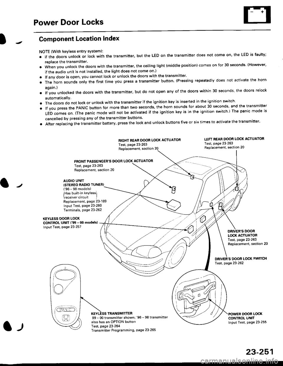
Component Location Index
NOTE (With keyless entry systeml:
. It the doors unlock or lock with the transmitter, but the LED on the transmitter does not come on, the LED is faulty;
replace the transmitter'
. when vou unlock the doors with the transmitter, the ceiling light (middle position) comes on for 30 seconds. (However,
if the audio unit is not installed, the light does not come on )
. lf any door is open, you cannot lock or unlockthe doors with the transmitter'
. The horn sounds only the first time you press a transmitter button. (Pressing repeatedly does not activate the horn
again.)
o lf vou unlocked the doors with the transmitter, but do not open any of the doors within 30 seconds, the doors relock
automatically.
. The doors do not lock or unlock with the transmitter if the ignition key is inserted in the ignition switch
. lf you press the PANIC button for more than two seconds, the horn sounds for about 30 seconds, and the transm'fer
LED comes on. (The panic mode will not be activated iJ the ignition key is in the ignition switch ) The panic mode is
cancelled by pressing any of the transmitter buttons'
o After replacing the transmitter battery, press the lock and unlock buttons five or six times to activate the transmitter'
Replacement, section 20
FRONT PASSENGER'S DOOR LOCK ACTUATOR
RIGHT REAR DOOR LOCK ACTUATOR
Test, page 23-263
I.IFT REAR DOOR LOCK ACTUATOR
Test, page 23 263Replacement, section 20
LOCK ACTUATORTest, page 23-263Replacement, section 20
ORIVER'S DOOR LOCK SWITCH
Test, page 23'262
DOOR L@XCONTROL UN]TInput Test, page 23 255
23-251
Test, page 23-263Replacement, section 20
AUDIO UNIT(STER€O RADIO TUNER)
{'96 - 98 models)
lHas built-in keylessl
eceiver circuit IReplacement, page 23-189
Input Test, page 23-260
Terminals, page 23-262
KEYLESS DOOR LOCKCONTROL UNIT l'99 - 00 modelsl
Input Test, Page 23-257
l-l
TRANSMITTER99 - 0O transmitter shown;'96 -98 transmifter
also has an OPTION buttonTest, page 23-264Transmitter Programming, page 23_265
Qi,,a/
/----
L(ru
i'.-8,-'l
/'-'6
Page 1728 of 2189
Power Door Locks
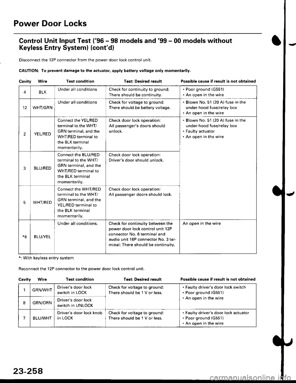
Control Unit lnput Test ('96 - 98 models and'99 - 00 models without
Keyless Entry Systeml (cont'dl
Disconnect the 12P connector from the power door lock control unit.
CAUTION: To prevsnt damage to the actuator, apply battery voltage only momentarily.
Cavity WireTest conditionTest: Desired resultPossible cause if result is nol obtained
*: With keyless entry system
Reconnect the 12P connector to the power door lock control unit.
Cavity WireTest conditionTssl: Desirsd losullPossible cause it resull b not obtained
4BLKUnder all conditionsCheck for continuity to ground:
There should be continuity.
. Poor ground (G55'l ). An open in the wire
WHT/GRN
Under all conditionsCheck for voltage to ground:
There should be battery voltage.
. Blown No. 51 (20 A)fuse in the
under-hood fuse/relay box. An open in the wire
2YEURED
Connect the YEURED
terminal to the WHT/
GRN terminal, and the
WHT/RED terminal to
the BLK terminal
momenraflty.
Check door lock operation:
All passenger's doors should
untocK.
Blown No. 51 {20 A) fuse in the
under-hood fuse/relay box
Faulty actuator
An open in the wire
3BLU/RED
Connect the BLU/RED
terminal to the WHT/
GRN terminal. and the
WHT/RED terminal to
the BLK terminal
momenraflry.
Check door lock operation:
Driver's door should unlock.
5WHT/RED
connect the WHT/RED
terminal to the WHT/
GRN terminal, and the
YEL/RED terminal to
the BLK terminal
momenrafl ty.
Check door lock operation:
All passenger doors should lock.
BLU/YEL
Under all conditions.Check for continuity between the
power door lock control unit l2P
connector No. 6 terminal and
audio unit 16P connector No. 3 ter-
minal: The.e should be continuity.
An open in the wire
GRN,ryVHTDriver's door lock
switch in LOCK
Check for voltage to ground:
There should be 1 V or less.
Faulty driver's door lock switch
Poor ground {G551)
An open in the wire
8GRN/ORNDriver's door lock
switch in UNLOCK
7BLUA/VHT
Driver's door lock knob
in LOCK
Check for voltage to ground:
There should be 1 V or less.
Faulty driver's door lock actuator
Poor ground {G551)
An open in the wire
Page 1729 of 2189
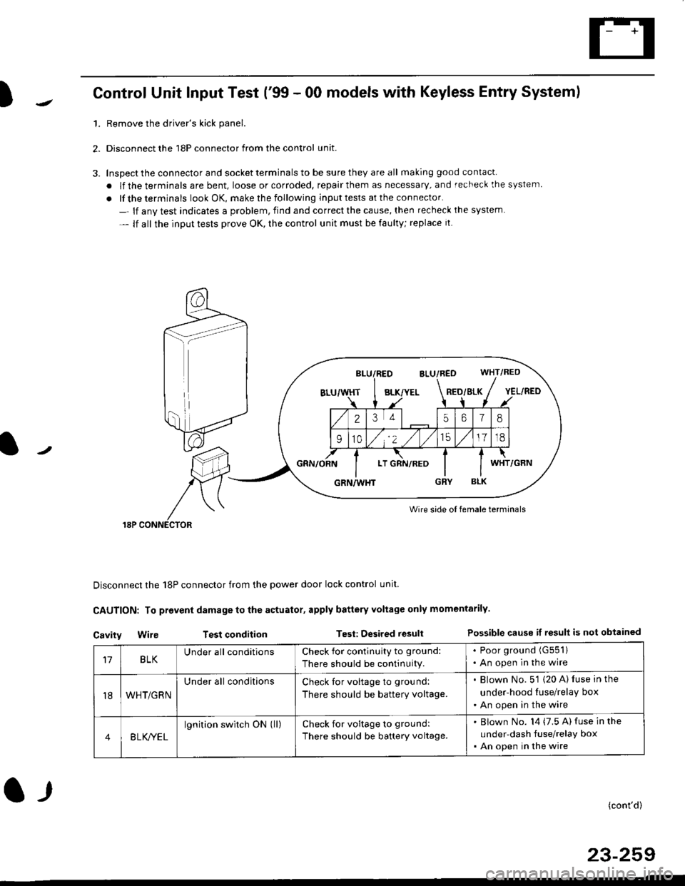
)Control Unit Input Test ('99 - 00 models with Keyless Entry System)
1.Remove the driver's kick panel.
Disconnect the 18P connector from the control unit.
Inspect the connector and socket terminals to be sure they are all making good contacl.
. lf the terminals are bent, loose or corroded, repair them as necessary, and recheck the system
. lf the terminals look OK, make rhe following input tests at the connector.
- lf anv test indicates a problem, find and correct the cause, then recheck ihe system
- lf all the input tests prove OK, the control unit must be faulty; replace it
Wire side oI female terminals
Disconnect the 18P connector from the power door lock control unit.
CAUTION: To provent damage to the actuator, apply battery Yoltage only momentarily.
Cavity Wir€ Test conditionTest: Desired resultPossible cause if result is not obtained
BLK/YELRED/SLK
25618
910/,'2 ,/
'151718
LTWHT
17BLKUnder all conditionsCheck for contlnuity to ground:
There should be continuity.
. Poor ground (G551)
. An open in the wire
t8WHT/GRN
Under all conditionsCheck tor voltage to ground:
There should be battery voltage.
. Blown No. 5'1 (20 A) luse in the
under-hood tuse/relay box
. An open in the wire
4B LK/YEL
lgnition switch ON (ll)check for voltage to ground:
There should be battery voltage.
Blown No. l4 (7.5 A) fuse in the
under-dash fuse/relay box
An open in the wire
(cont'd)
23-259
l-r
Page 1733 of 2189
)
l-l
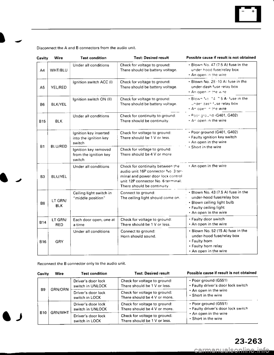
Disconnect the A and B connectors from the audio unit.
Cavity WireTest conditionTest: Desired resultPossible cause if result is not obtained
Reconnect the B connector only to the audio unit.
Cavity WireTest conditionTest: Desired resultPossible cause iI result is not obtained
B9GRN/ORN
Driver's door lock
switch in UNLOCK
Check for voltage to ground:
There should be 1 V or less.
. Poor ground 1G551). Faulty driver's door lock switch. An open in the wire. Short in the wireDriver's door lock
switch in LOCK
Check for voltage to grou nd:
There should be 4 V or more.
810G R NAr'r'HT
Driver's door lock
switch in UNLOCK
Check for voltage to ground:
There should be 4 V or more.
. Poor ground (G551)
. Faulty driver's door lock switch. An open in the wire. Shon in the wireDriver's door lock
switch in LOCK
Check lor voltage to ground:
There should be I V or less.
23-263
A4WHT/BLU
LJnder all conditionsCheck {or voltage to ground:
There should be battery voltage.
. Blown No. 47 (7.5 A) tuse in the
under hood fuse,i relay box. An open n the w re
A5YEL/RED
lg nition swirch ACC (l)Check for voltage to ground:
There should be battery voltage.
Blown No. 28 , I0 A) f use in the
under dash fuse.elay box
An open " :ne n re
Check for voltage to ground:
There should be battery voltage.
Check for continuity to groundr
There should be continuity.
B o$. \. '.1 - 5 A' iuse n the
,,^oe' aas_'-se relay box
A_ ooe^ ' :ne wrre
Pc.' E'o--d rG401, G402)
A- ooen n lhe wire
B6B LK,/YE L
lgnition switch ON0l)
8158LK
Under all conditions
B1BLU/RED
lgnition key inserted
into the ignition key
swrtch
Check for voltage to ground:
There should be 1 V or less
Check for voltage to ground:
There should be 4 V or more
Poor ground (G401, G402)
Faulty ignition key switch
An open in the wire
Short in the wire
An open in the wireCheck for continuity berwee. lFe
audio unit 16P connector l-o 3ler-
minal and power door lock control
unit 12P connector No. 6 lermrnal:
There should be continu ty
lgnition key removed
from the ig nition key
swtlcn
B3B LUlt/E L
U nderall conditions
B8LT GRN/
BLK
Ceiling light switch in"middle position"
Connect to ground:
The ceiling lighr shouldcome on.
Blown No.43 (7.5 A) fuse in the
under-hood Iuse/relay box
Blown ceiling light bulb
Fau lty ceiling light
An open in the wire
814LT GRN/
RED
Each door open, one at
a time
Check tor voltage to ground:
There should be'l V or less.
. Faulty door switch. An open in the wire
Br6GRY
U nderall conditionsConnect to groundl
Horn should sound.
. Blown No. 52 ('15 A) fuse in the
under-hood fuse/relay box
. Fau lty horn. Faulty horn relay. An open in the wire
Page 1735 of 2189
l
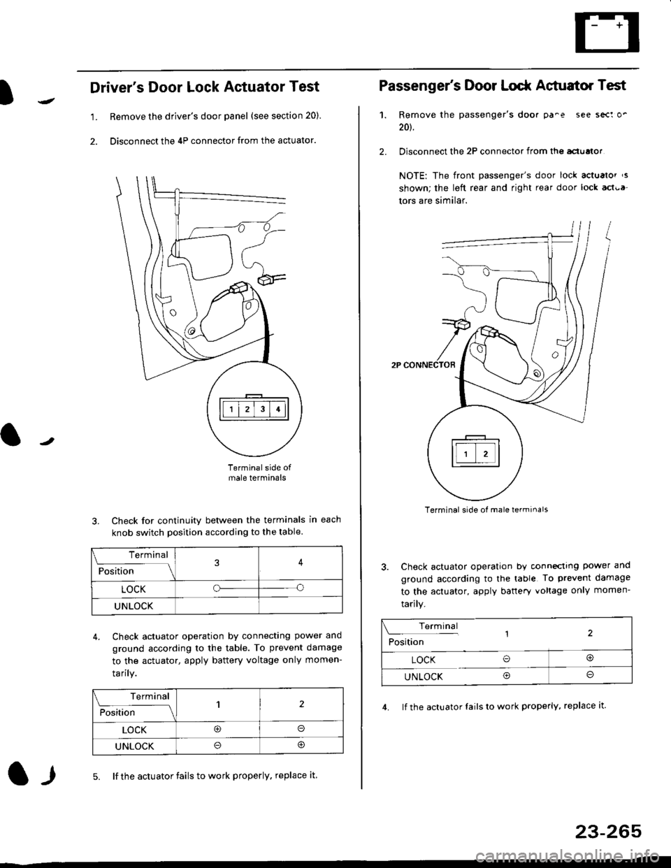
Driver's Door Lock Actuator Test
1. Remove the driver's door panel (see section 20).
2. Disconnect the 4P connector from the actuator.
J
Terminalside ofmale terminals
3. Check for continuity between the terminals in each
knob switch position according to the table.
4. Check actuator operation by connectlng power ano
ground according lo the table. To prevent damage
to the actuator, apply battery voltage only momen-
tarilY.
l-l5. lf the actuator fails to work properly. replace it
23-265
Terminal
F""lti* - lll
LOCKo
UNLOCK
Terminal
Fo"JJ'-lrlon';" -ll1
LOCK@o
UNLOCK
Passenger's Door Lodr Actuator Test
1.
2.
Remove the passenger's doo. pa^e see sect o'
201.
Disconnect the 2P connector from lhq aclualor
NOTE: The front passenger's door lock actualor ,s
shown; the left rear and right rear door lock act{,a
tors are similar.
Terminal side ol male terminals
3. Check actuator operation by conneclrng power and
ground according to the table To prevent damage
to the actuator, apply banery voltage only momen-
tarily.
4. lf the actuator Iails to work properly, replace it.
Terminal,2Position
LOCK O@
UNLOCK Oo