Page 295 of 2189
![HONDA CIVIC 1999 6.G Workshop Manual System Description
Vacuum Connections (contd)
Dl6Y7 angin6 (97 coup.: KL mod€l, sedan: KL (LX) model,,9g modet):
i1] PRIMARY HEATED OXYGEN SENSOR (PRIMARY HO2S,SENSOR 1)E) SECONDARY HEATED OXYGEN HONDA CIVIC 1999 6.G Workshop Manual System Description
Vacuum Connections (contd)
Dl6Y7 angin6 (97 coup.: KL mod€l, sedan: KL (LX) model,,9g modet):
i1] PRIMARY HEATED OXYGEN SENSOR (PRIMARY HO2S,SENSOR 1)E) SECONDARY HEATED OXYGEN](/manual-img/13/6068/w960_6068-294.png)
System Description
Vacuum Connections (cont'd)
Dl6Y7 angin6 ('97 coup.: KL mod€l, sedan: KL (LX) model,,9g modet):
i1] PRIMARY HEATED OXYGEN SENSOR (PRIMARY HO2S,SENSOR 1)E) SECONDARY HEATED OXYGEN SENSOR {SECONDARYHO2S, SENSOR 2l€l MANTFOLD ABSOT_UTE PRESSUnE tMAp) SENSOR€r ENGINE COOLANT TEMPERATURE |ECT) SENSOR€] INTAKE AIR TEMPERATURE IIAT} SENSOR6 CRANKSHAFT SPEED FLUCTUATION ICKFI SENSOR17 IOLE AIR CONTROL IIACI VALVE@ THRoTTLE BoDY {TBIO FUEL INJEGToR(9 FUE|- FTLTEFO FUEL PRESSURE REGULAToR@ FUEL PUMP {FPI(D FUEL TANK@ FIFL TANK EVAPoRATIVE EMIssIoN {EVAPIVALVE(, AIR CLEANER
(tO RESONATORl? PoSITIVE cRANKcAsE VENTILATIoN IPcv}VALVEIA EVAPORANVE EMISSION TEVAPI PURGE CONTROLSOLENOID VALVE19 EVAPORATIVE EMISSION IEVAPI CONTROL CANISTERE EVAPORATIVE EMISSION (EVAPIBYPASS SOLENOIDVALVE€' EVAPoRATIVE EMIssIoN IEVAPI THREE wAY vALvEQ' EVAPORATIVE EMISSION IEVAPI CONTROL CANISTERVENT SHUT VALVE@ FUEL TANK PRESSURE sENsoR{?1! EVAPORANVE EMISSION IEVAPI TWO WAY VALVE?5 THREE WAY CATALYTIC CONVERTER ITWC'
11-26
Page 296 of 2189

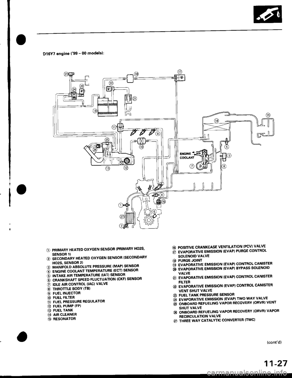
Dl6Y7 engins ('99 - 00 modelsl:
PRIMARY HEATED OXYGEN SENSOR {PRIMARY HO2S,
SENSOR 1)iiconoanv neareo oxYGEN sENsoR ISECoNDARY
HO2S, 9ENSOR 2)MANIFOLD ABSOLUTE PRESSURE (MAP) SENSOR
ENGINE COOLANT TEMPERATURE (ECT} SENSOR
INTAKE AIR TEMPERATURE (IATI SENSOR
CRANKSHAFT SPEED FLUCTUATION ICKFI SENSOR
IOLE AIR CONTROL (IAC} VALVE
THROTTLE BODY (TBl
FUEL INJECTORFUEL FILTERFUEL PRESSURE REGULATOR
FUEL PUMP (FP)
FUEL TANKAIR CLEANERRESONATOR
6d POSITIVE CRANKCASE VENTILATION (PCV) VALVE
6 rvapoamve eutssloN tEvAP) PURGE coNTRoL
SOLENOID VALVECO PURGE JOINT6 evlponnnve eutssloN (EvAPl coNTRoL cANlsrER
i evlponnnve eussloN {EVAP} BYPASS solrNolD
VALVE
6) EVAPORATIVE EMISSION (EVAPI CONTROL CANISTEN
FILTER
@ EVAPORATIVE EMISSTON (EVAP) CONTROL CANISTER
VENT SHUI VALVEA FUEL TANK PRESSURE SENSON
d rvlpoamve emtsstoN tEvAPl rwo wAY vALvE
6 orueonno nerueLING vAPoR REcovERY loRvnl vENT
SHUT VALVE
€) ongolno neruellNc VAPOR RECOVERY {ORVR) VAPOR
RECIRCULATION VALVE
€) THREE WAY CATALYTIC CONVERTER (TWC)
a
6t
@!.,
o@ao
@@
(}
@@
(cont'd)
11-27
Page 297 of 2189

I
a
System Description
Vacuum Connections (cont'd)
816A2 engine:
@ EvApoRATtvE EMtsstoN tEvAp) puRGE coNTRoLSOLENOID VALVE@ PURGE JoINT€t EvApoRATtvE EMtsstoN (EVApt coNTRoL caNtsTERQA EVAPORATIVE EMISSION (EVAP) BYPASS SOLENOIDVALVE
@ EVApoRATtvE EMtsstoN lEvApl coNTRoL caNtsrERFILTER@ EvApoRATtvE EMtsstoN {EvApt coNrRoL cANtsrERVENT SHUT VALVE@ FUEL TANK PRESSURE sENsoRGI EVAPORATIVE EMISSION (EVAP} TWO WAY VALVE@ ONBOARD REFUETING VAPOR RECOVERY {ORVR} VENTSHUT VALVE@ oNBoAnD REFUELING vApoR REcovERy (oRvRl vApoR. RECIRCULATION VALVE(c} THREE WAY CATALYTIC CONVERTER {TWCI
(' PRIMARY HEATED OXYGEN SENSOR IPRIMARY HO2S.SENSOR 1l.?) SECONDARY HEATED OXYGEN SENSOR {SECONDARYHO2S, SENSOR 2)13] MANIFOLD ABSoLUTE PRESSURE (MAP) sENsoBi' ENGINE COOLANT TEMPERATURE IECT) SENSORO INTAKE AIR TEMPERATURE ITATI SENSORi6l KNOCK SENSOR {KS}O oRANKSHAFT SPEED FLUCTUATIoN {cKF} sENsoR@ IDLE AIR coNTRoL (IAc} VALVE€) THRoTTLE BoDy trB|(D FUEL INJECToRO FUEL PULSATIoN DAMPER[D FUEL FILTER@ FUEL PRESSURE REGULAToR!I FUEL PUMP IFP)f,' FUEL TANK(iD ArR CLEANERt' RESONAToR'.1]i POSITIVE cRANKcAsE VENTILATIoN {Pcv} VALVE
11-28
Page 354 of 2189
Probable Cause List lFor th€ DTC Chart, see page 11-971*: '99 - 00 models
Probable GausePageSystem
11 1-107Engine Control Module (ECM)/Powertrain Control Module (l'uM)
PGM-Fl main relay
l^^iti^n cwetam
211-230,231
3't't-237
Section 23
51'�1-172,183Crankshaft Position/fop Dead Center/Cylinder Fosltlon sensor clrculr'� Lr\F selrsor
circuit
Intake Air Temperature (lAT) sensor circuit
ldle Air Control (lAC) Valve
ldle speed adjustment
Throttle bodY
Throftle cable
Manifold Absolute Pressure (MAP) sensor
Throftle Position (TP) sensor
Barometric pressure (BARO) senso'
Mf g"a, po"ition signal (see page 11-216) or clutch switch signal
Brake switch signal
Air Cleaner
lntake air pipe
Three Way Catalytic Converter (TWC)
Evaporative emission (EVAP) control
Contaminated fuel
ORVR vent shut valvs
't1-124
71 1-194
I11-220 - 223
11-241
'1011-244
1111-115
1211-132
13't1-178
14Section 14. 11-218
1511-210
16't1-244
1811-252
1911-261
20
21*11-296
(cont'd)
11-85
Page 368 of 2189

,'o
L
*:The E indicator light and the Maltunction Indicator Lamp (MlL) may come on simultaneously.*1: D16Y5 engine (CVT)"5: '96 D16Y5 engine, D16Y7 engine, D16Y8 engine (sedan).'97 D16Y5 engine, Dl6Y7 engine (coupe: KA, KC models, sedan: KA.
KC, KL (DX) models, hatchback: all models), D16Yg engjne (sedan: KA, KC models)*6: '96 D16Y8 engine (coupe),'97 Dl6Y7 engine (coupe: KL model, sedan: KL (LX) model),'97 D'16Y8 engine (coupe: all models,
sedan: KL model),'98-all models,'99-all models,'00-all models*12: Except A,,/T (D16Y7, D16Y8 enginei*13: A"/T (D16Y7, D16Y8 engine)!l*14:'97 model*16:'98 model" 17: '99 - 00 models
(cont'd)
1 1-99
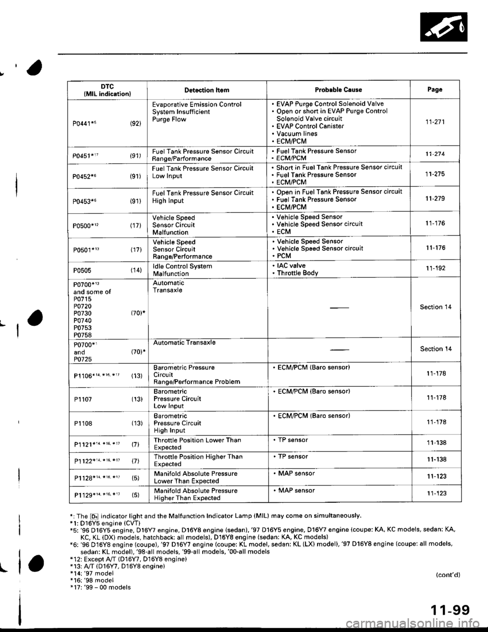
DTC{MlL indication}Detoction lt€mProbable C.usePage
P0441*5 (92)
Evaporative Emission ControlSystem InsufficientPurge Flow
EVAP Purge Control Solenoid VaiveOpen or short in EVAP Purge Control
Solenoid Valve circuitEVAP Control CanisterVacuum linesECM/PCM
11-271
P0451'11 (91)FuelTank Pressure Sonsor CircuitRange/Parformance
. FuelTank Pressure Sensor' ECM/PCM11 274
P0452{6(9r )
Fuel Tank Pressure Sensor CircuitLow Input
Short in FuelTank Pressure Sensor circuatFuel Tank Pres$ure SensorECM/PCM
11-275
P0453*6 {91)
Fuel Tank Pressure Sensor Circuit
High Input
ODen in Fuel Tank Pressure Sensor circuit
Fuel Tank Pressure Sensor
ECM/PCM
11-219
P0500*1, (17)Vehicle SpeedSensor CircuitMalfunction
V€hicle Speed SensorVehicle Speed Sensor circuit
ECM
11-176
P0501*'3 l17l
Vehicle SpeedSensor CircuitRange/Performance
V€hicle Sp€ed SensorVehicle Speed Sensor circuitPCM
r 1- 176
P0505 (14)ldle Control Systemlvl a lfu n ctio n
. IAC valve. Throttle Body11-192
P0700*r3and some ofP0715P0720P0730 (70)*
P0740P0753P0758
AutomaticTransaxle
Section 14
P0700*1and (70)*
P0725
Automatic TransaxleSection 14
(13)Barometric PressureCircuitRange/Performance Problem
. ECM/PCM (Baro sensor)1 1-178
P1107 (13)BarometricPressure CircuitLow Input
. ECM/?CM (Baro s€nsor)11-178
P1108 (13)BarometricPressure CircuitHigh Input
. ECM/PCM lBaro sensor)1 1-178
P1121*'. *16. *'? \71Throttle Position Lower ThanExpected
. I r sensor11-138
P1122'14.*16.*n 17lThrottle Position Higher ThanExpected
. TP sensor11-'138
15)Manifold Absolute PressureLower Than Expected
. MAP sensor1 1'123
P1129*1r.*16.*"(5)Manifold Absolute PressureHigher Than Expected
. MAP sensor't1-123
Page 461 of 2189

ldle Control System
ldle ControlSystem
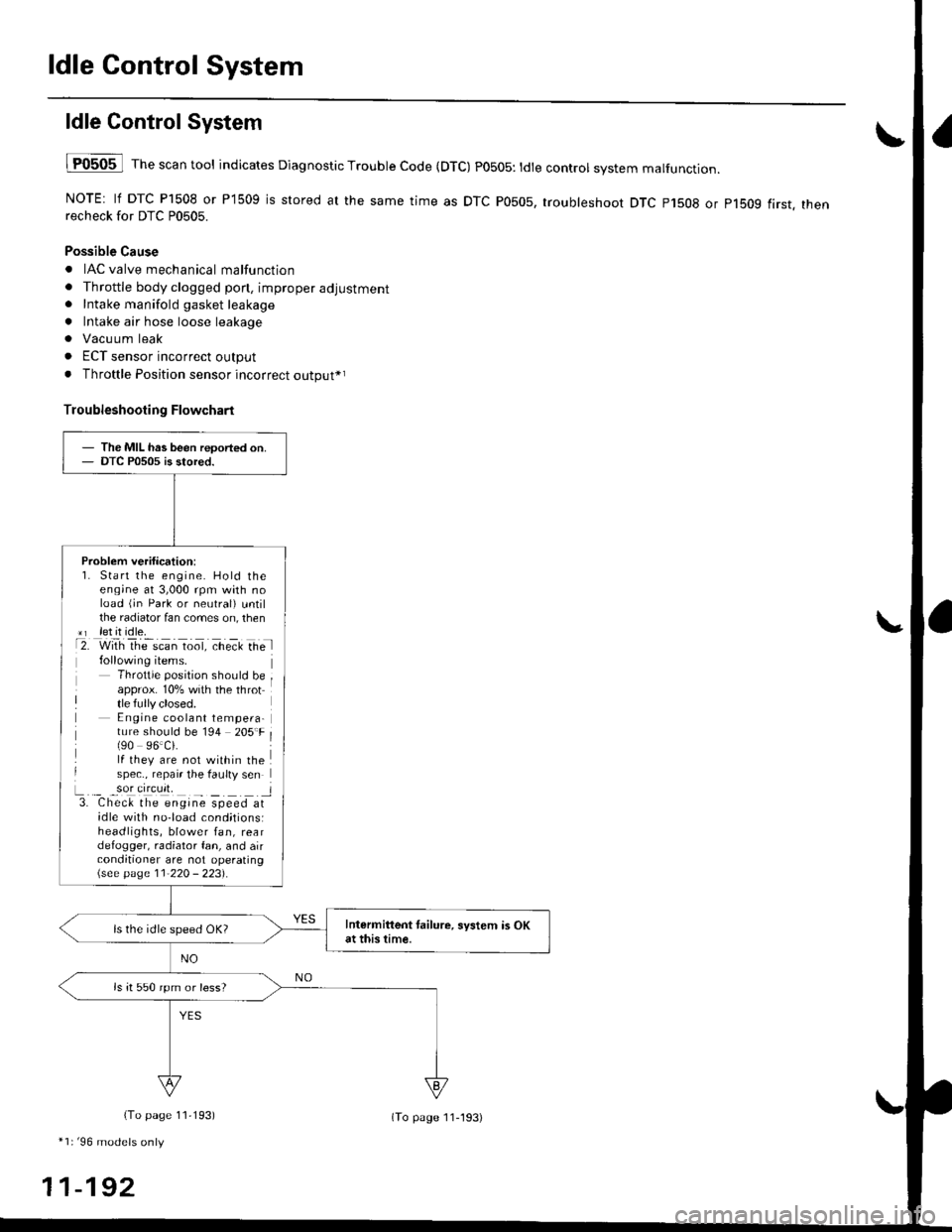
lF0505 l Th" """n tool indicates Diagnostic Trouble Code (DTC) PO5O5: tdte controt system malfunction.
NOTE: lf DTC P1508 or P1509 is stored at the same time as DTC P0505, troubleshoot DTC p1508 or p1bog first. thenrecheck for DTC P0505.
Possible Cause
. IAC valve mechanical malfunction
. Throttle body clogged pon, improper adjustment. Intake manifold gasket leakage
. Intake air hose loose leakage
. Vacu um leak
. ECT sensor incorrect output
. Throttle Position sensor incorrect output*r
Troubleshooting Flowchart
The MIL has been reoorted on.DTC P0505 is stored.
Problem verification:1. Start the engine. Hold theeng;ne at 3,000 rpm with noload (jn Park or neutral) untilthe radiator fan comes on, then*r let it idle.t2. with rhe scan toot, ct'eit Ge l
Throttle position should beapprox. 10% with the throttle fully closed.E ngine coolant tempera-ture should be 194 205'F(90 96.Ci.lf they are not within thespec., repair the faulty sen
L._ _9oI9[cr]41 l3. Chec& the engine speed atidle with no-load cond;tionsiheadlights, blower fan, reardefogger, radiator fan, and airconditioner are not operating\see page l1-22O - 223).
Intermittent tailure, system is OKat this time.ls the idle speed OK?
ls it 550 rpm or less?
(To page 11,193)
*1r'96 models only
11-192
(To page ll-193)
Page 462 of 2189
I
L
1D16Y5, D16Y8 engine with M/T 81642 engine)I
D16Y7 engine:
{From page 11-192)
Check the IAC valve:Disconnect the 3P connector from
the IAC valve.
Check the IAC valve:Disconnect the 2P connectorfrom the IAC valve.
Does the engine speed drop or
the engine stall?
Adiust the {base} idle speod (see
page 11-220 - 2231.It it's impos-
aible, clean the ports in lhe throt'
tle bodv,
(From page 11-192i
Check Ior vacuum leaks:1. Turn the ignition switch OFF.2. Remove the intake air ductfrom the throttle body.
3. Start the engine and let it idle.
4. Put your finger on the lowerpon in the th.ottle body.
Ch€ck tor vecuum loaks, m.kesure the throttle valve is com_pletaly closed, end repair as nec-Does the engine speed droP?
Adiust the idle speed (see page
11-220 - 2231. lf it's impossible,
reolace the IAC velve.UPPERPORT
1 1-1 93
Page 463 of 2189

ldle Control System
ldle Air Control (lACl Vatve ('96 - 98 Dl6ys, Dl6yB engine with M/Tl
The scan tool indicates Diagnostic Trouble Code (DTC) P1508: A problem in the ldle Air Controt flAC) varvecircuit.
The IAC Valve changes the amount of air bypassing the throttle body in response to a current signal from the ECM inorder to maintain the proper idle speed.
IAC VALVE 2P CONNECTOR ICl3A)
,flrcerh-:J iYEL/BLKI
!.__-,/ -lt(v)
-T-=
Wire side of female terminals
tAcv(BLK/
ELUI
ECM CONNECTOR A I32PI
Wire side oI lemal€ terminals
VALVE
6a10ll12t3r5t6l7t8t920232a
t*25&a2A3o
The MIL hss b€on repo.ted on.DTC P'l508 i. itorod.
Problem vorification:1. Do the ECM/PCM Reset Pro-cedure,Start the engine, and warm ituP to normal operating tem-perature.
Intormittont t!llur., sy.tcm b OKat thb tim6. Chsck fol poor con-ncctionr or loo3e wirot at C138(lAC valv.l.nd ECM.
ls DTC P1508 indicated?
Check for an opcn in the wiro(lGPl line):1. Turn the ignition switch OFF.2. Disconnect the IAC valve 2Pconnector.3. Turn the ignition switch ON (ll).
4. Measure vohage between bodyground and the IAC valve 2Pconnectorterminal No. 2.
R.prir opan in the wiro botwa.nIAC valv..nd PGM-FI main r.l.y.
Chock for an opon or sho in thewire (IACV linal:1. Turn the ignition switch OFFand reconnect the IAC valveconnector.2. Disconnect the ECM connectorA (32P).
3. Turn the ignit;on switch ON (ll).4. Measure voltage betweenbody ground and ECM con-nector terminal A12.
(To page 1l-195)
11-194