Page 1300 of 2189
Dashboard
Gomponent Removal/lnstallation
(cont'd)
Center panel removal:
1. Remove:
. Center dashboard lower cover (see page 20-69)
. Radio {see section 23)
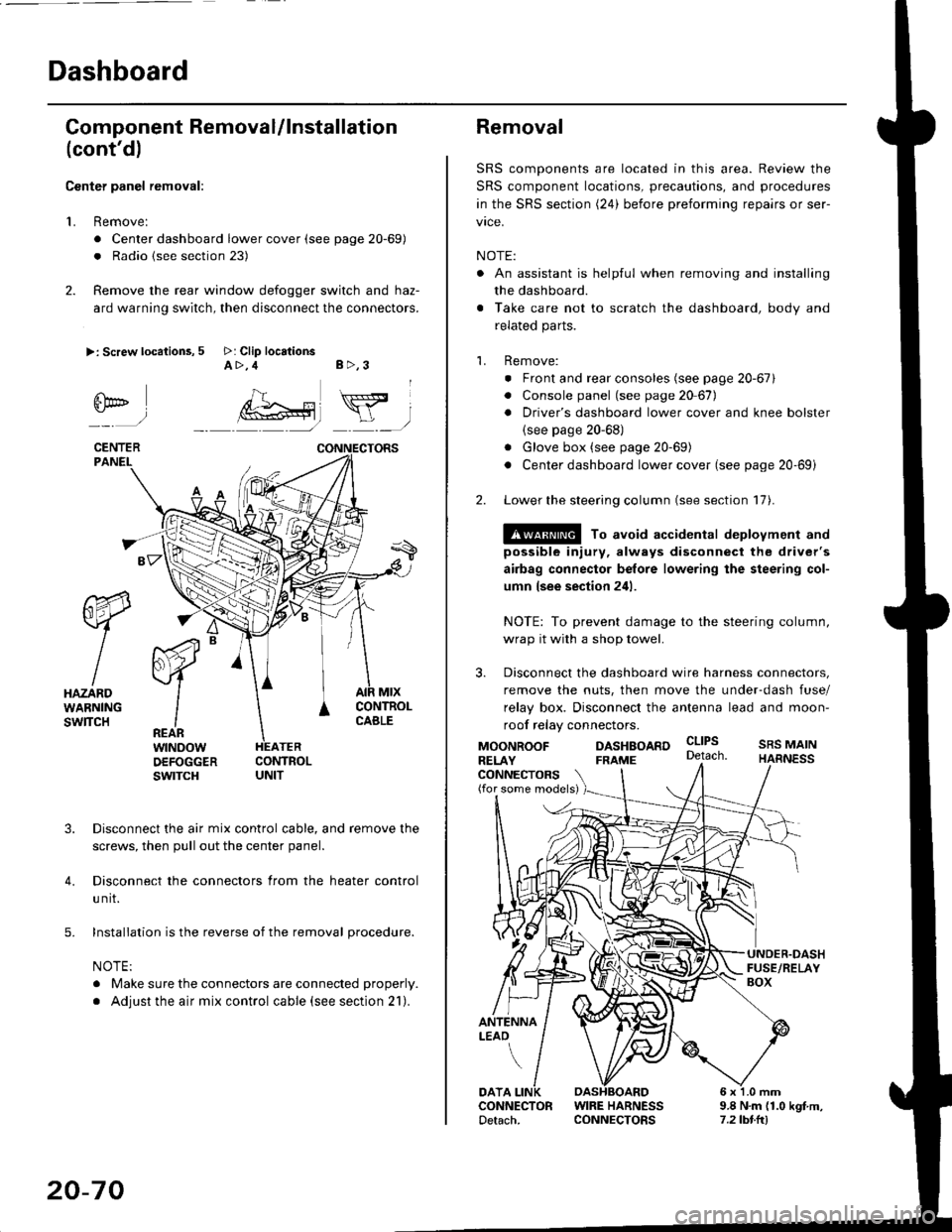
2. Remove the rear window defogger switch and haz-
ard warning switch, then disconnect the connectors.
>: Screw locations, 5 >: Clip locationsA>,4 B>,3
fii*-)
CENTERPANEI.
rt-xR.
W
IHAZARDWARNINGswlTcH
r44 "
F.IZvl
IIREARwtNoowOEFOGGERswtrcH
MtxCONTNOLCABLE
3. Disconnect the air mix control cable, and remove the
screws, then pull out the center panel.
4. Disconnect the connectors from the heater control
u nit.
5. Installation is the reverse of the removal procedure.
NOTE:
. Make sure the connectors are connected properly.
. Adjust the air mix control cable (see section 21).
20-70
Removal
SRS components are located in this area. Review the
SRS component locations, precautions, and procedures
in the SRS section (24) before preforming repairs or ser-
vice.
NOTE:
. An assistant is helpful when removing and installing
the dashboard.
. Take care not to scratch the dashboard, body and
related parts.
1. Remove:
o Front and rear consoles (see page 20-67)
. Console panel (see page 2O 67),
. Driver's dashboard lower cover and knee bolster(see page 20-68)
. Glove box (see page 20-69)
. Center dashboard lower cover (see page 20-69i
2. Lower the steering column (see section 17).
@ To avoid accidental deplovment and
possible injury, always disconnect the driver's
airbag connector belore lowering the steering col-
umn lsee section 241.
NOTE: To prevent damage to the steering column,
wrap it with a shop towel.
3. Disconnect the dashboard wire harness connectors,
remove the nuts, then move the under-dash fuse/
relay box. Disconnect the antenna lead and moon-
roof relay connectors.
DASHBOARD cltPs
CONNECTORS(for some models)
MOONROOFRELAY
ANTENNALEAO
FRAME
SRS MAINHARNESS
9.8 N.m (1.0 kgf m,7.2lbt.ltl
DATACONNECTOR WIRE HARNESSDetach. CONNECTORS
Page 1555 of 2189
Under-dash Fuse/RelaY Box
Removal/lnstallation
SRS components are located in this area. Review lhe
SRS component locations, precautions, and procedures
in the SRS section (24) before performing repairs or ser-
vice.
Removal:
1. Make sure you have the anti-lheft code for the radio
then write down the frequencies lor the radio's pre-
set buttons ('99 - 00 modelsl.
2. Disconnect the battery negative cable. then discon
nect the positive cable, and wait at least three min
utes,
3. Disconnect the airbag connectors (see section 24)'
4. Remove the driver's dashboard lower cover and
knee bolster (see section 20)
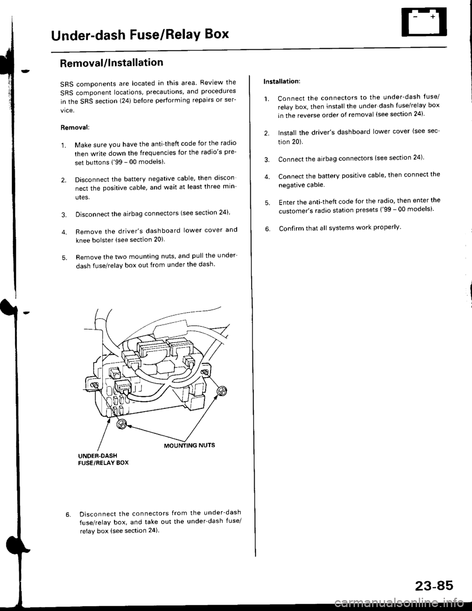
5. Remove the two mounting nuts, and pull the under
dash fuse/relay box out from under the dash'
6. Disconnect the connectors from the under-dash
fuse/relay box, and take out the under-dash fuse/
relay box (see section 24).
lnstallation:
1. Connect the connectors to the under-dash tuse/
relay box, then install the under dash fuse/relay box
in the reverse order of removal (see section 24)'
2. Install the driver's dashboard lower cover (see sec
tion 20).
3. Connect the airbag connectors {see section 24)
4. Connect the battery positive cable, then connect the
negative cable.
5. Enter the anti-theft code lor the radio, then enter the
customer's radio station presets ('99 - 00 models)'
6. Confirm that all sYstems work properly'
23-45
Page 1559 of 2189
lgnition Switch
4.
Test
SRS components are located in this area Review the
SRS component locations. precautions. and procedures
in the SRS section {24} before performing repairs or ser-
1. i/ake sure you have the anti-theft code for the
radio, then write down the frequencies for the
radio's preset buttons ('99 - 00 models).
2. Disconnect the battery negative cable.
3. Remove the driver's dashboard lower cover and
knee bolster (see section 20).
Disconnect the 5P connector from the under dash
fuse/relay box and the 7P connector from the main
wire harness.
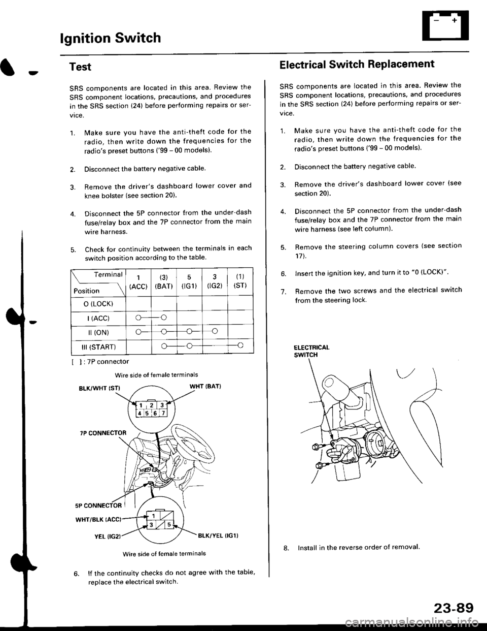
Check for continuity between the terminals in each
switch position according to the table.
I I :7P connector
Wire side ot female terminals
BLK/WHT {STIWHT IBAT}
7P CONNECTOR
WHT/BLK
YEL (IG2}BLK/YEL {IG1)
Wire side of female terminals
6. lf the continuity checks do not agree with the table,
replace the electrical switch.
Terminal
Position
1
(ACC)
(3)
(BAT)
5
{tG1) G2)
(1)
(sr)
o (LocK)
| (ACC)o--o
l (oN)o-o
III (START)o--o
1.
Electrical Switch RePlacement
SRS components are located in this area. Review the
SRS component locations, precautions, and procedures
in the SRS section \24) belore performing repairs or ser-
vtce.
1. Make sure you have the anti-theft code for the
radio, then write down the frequencies for the
radio's preset buttons {'99 - 00 modelsl.
2. Disconnect the battery negatlve cable.
3. Remove the driver's dashboard lower cover {see
section 20).
Disconnect the 5P connector from the under-dash
fuse/relay box and the 7P connector from the main
wire harness (see left column).
Remove the steering column covers {see section
11t.
lnsert the ignition key, and turn it to "0 {LOCK)".
Remove the two screws and the electrical switch
from the steering lock.
ELECTRICALswtTcH
8. Install in the reverse order of removal.
23-a9
Page 1560 of 2189
lgnition Switch
Steering Lock Replacement
SRS components are located in this area. Review theSRS component locations. precautions, and procedures
in the SRS section (24) before performing repairs or ser-vtce.
Remove:
LMake sure you have the anti-theft code for theradio, then wire down the frequencies for theradio's preset buttons ('99 - 00 models).
Disconnect the battery negative cable.
Remove the driver's dashboard lower cover andknee bolster (see section 20).
Disconnect the 5P connector from the under-dash
fuse/relay box and the 7P connector from the mainwire harness (see previous page).
Remove the steering column covers, then removethe mounting bolts and nuts from the steering col-umn (see section l7).
Lower the steering column assembly,
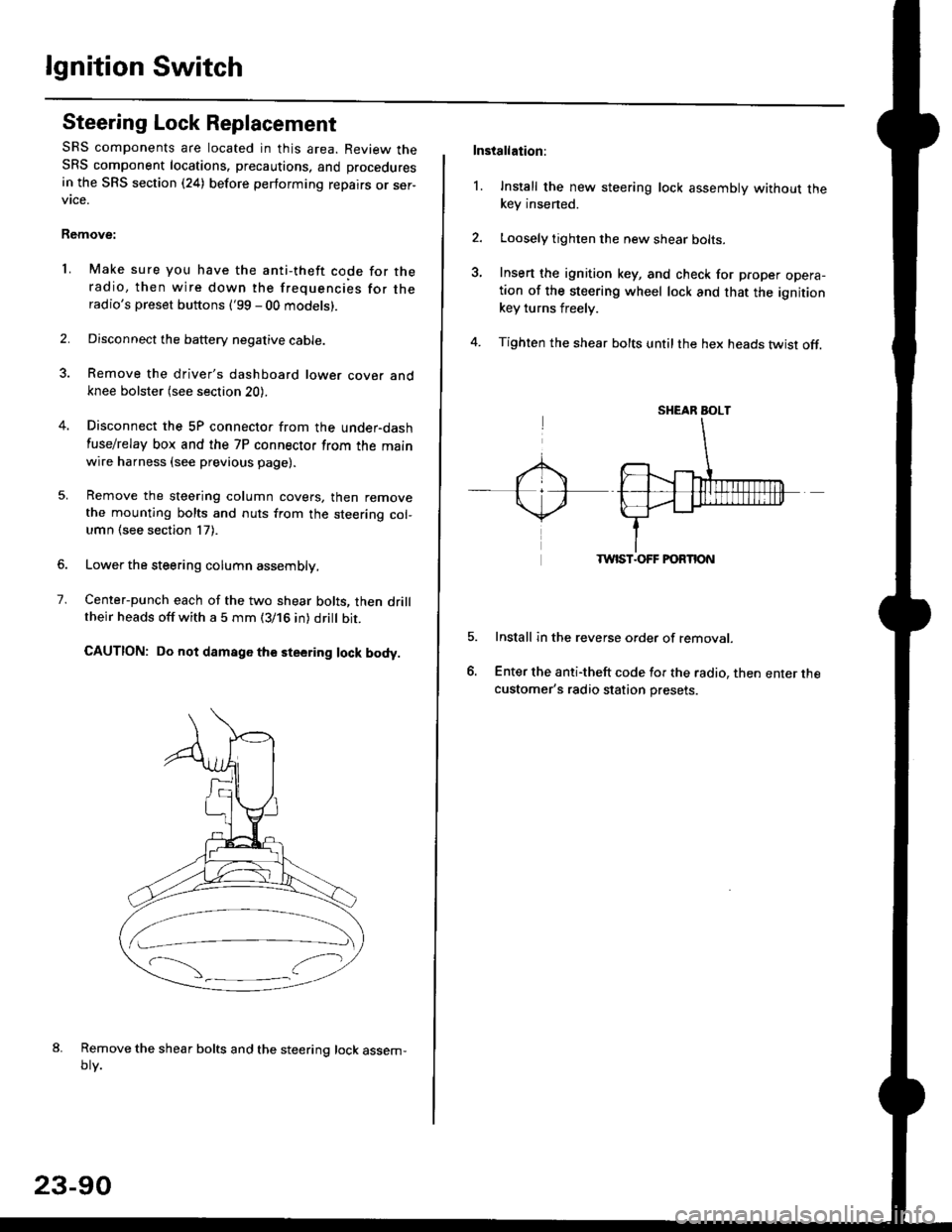
Center-punch each of the two shear bolts, then drilltheir heads off with a 5 mm (3/16 in) dritt bit.
CAUTION: Do not damago the steering lock body.
Remove the shear bolts and the steering lock assem,oty.
2.
1.
23-90
Installation:
l. Install the new steering lock assembly without thekey insened.
Loosely tighten the new shear bolts-
Insert the ignition key, and check for proper opera-tion of the steering wheel lock and that the ignitionkey turns freely.
Tighten the shear bolts untilthe hex heads twist off.
TWIST.OFF FORTION
Install in the reverse order of removar.
Enter the anti-theft code for the radio, then enter thecustomer's radio station presets.
sr{€aR SroLT
Page 1570 of 2189
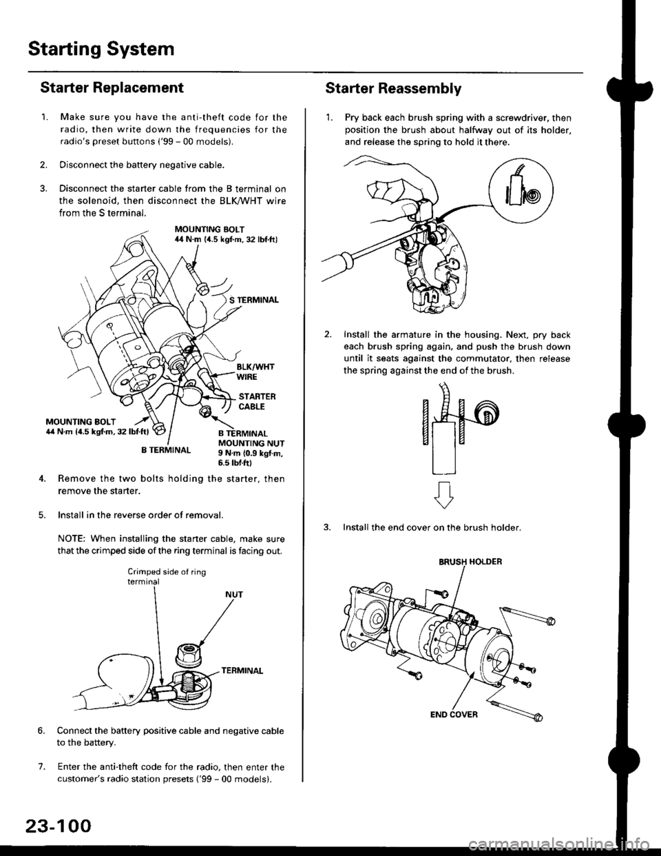
Starting System
Starter Replacement
1.Make sure you have the anti-theft code for the
radio, then write down the frequencies for the
radio's preset buttons ('99 - 00 models).
Disconnect the battery negative cable.
Disconnect the starter cable from the B terminal on
the solenoid, then disconnect the BLK trHT wire
from the S terminal.
MOUNTING BOLT44 N.m l/t.s kgf.m. 32 lbf.ft)
S TERMINAL
MOUNTING BOLT6,1 N.m {4.5 kstm.32lbtftl
MOUNTING NUT9 N,m {0.9 kgl.m,6.s lbtftl
B TERMINAL
4. Remove the two bolts holding the starter, then
remove the starter.
lnstall in the reverse order of removal.
NOTE: When installing the staner cable, make sure
that the crimped side ofthe ring terminal is facing out.
TERMINAL
Connect the battery positive cable and negative cable
to the battery.
Enter the anti-theft code for the radio, then enter the
customer's radio station presets ('99 - 00 models).
7.
Crimped side of ring
23-100
Starter Reassembly
'1. Pry back each brush spring with a screwdriver, then
position the brush about halfway out of its holder.
and release the spring to hold it there.
Install the armature in the housing. Next, pry back
each brush spring again, and push the brush down
until it seats against the commutator, then release
the spring against the end of the brush.
aw
3. Install the end cover on the brush holder.
ERUSH HOLDER
Page 1590 of 2189
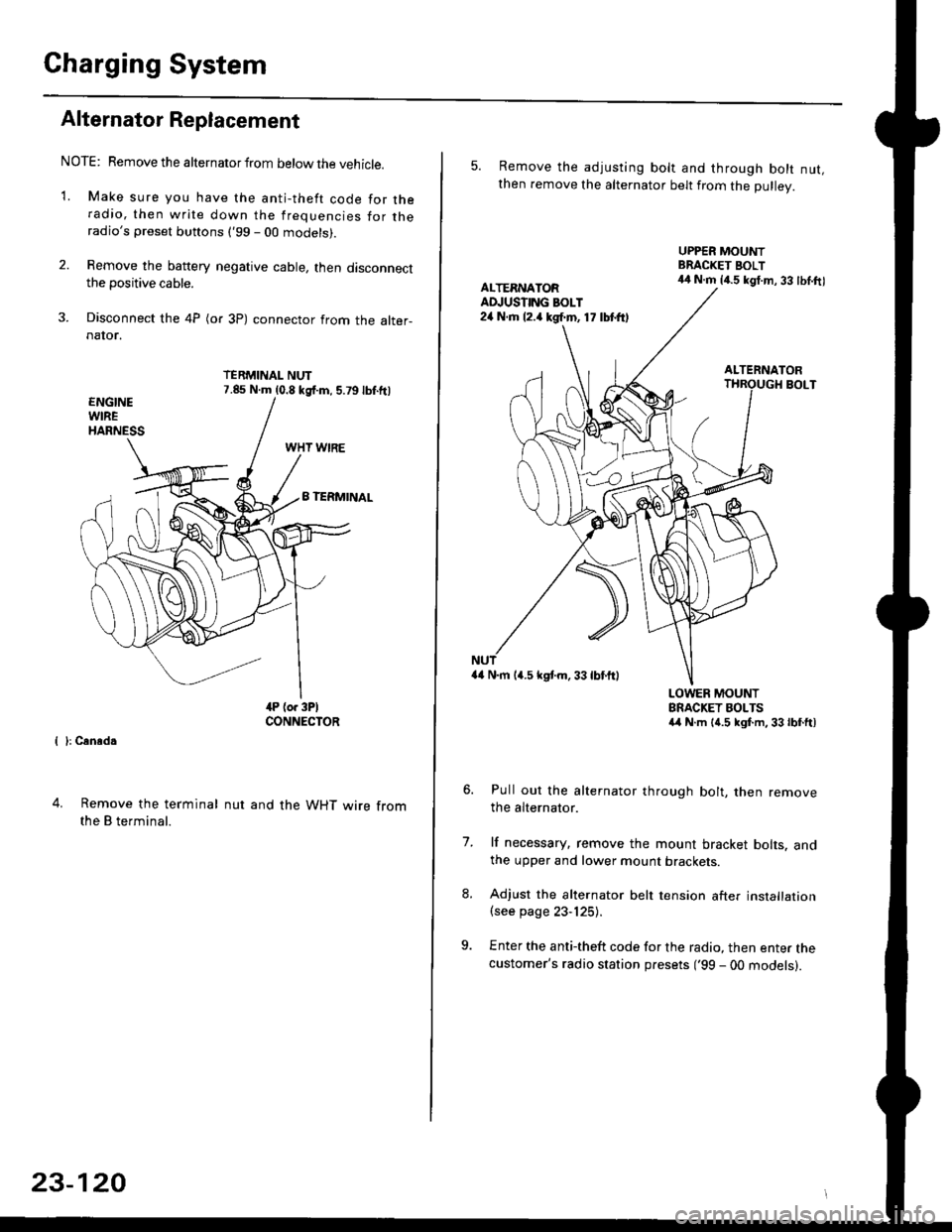
Charging System
Alternator Replacement
NOTE: Remove the alternator from below the vehicle.
'1. Make sure you have the anti-theft code for theradio, then write down the frequencies for theradio's preset buttons ('99 - 00 models).
2. Remove the battery negative cable, then disconnectthe positive cable.
3. Disconnect the 4P (or 3P) connector from the alter-naIor.
TERMINAL NUT7.85 N.m (0.8 kgf.m, 5.79lbf.ftl
{ }: Cansd.
4. Remove the terminal
the B terminal.
nut and the WHT wire from
23-120
5. Remove the adjusting bolt and through bolt nut,then remove the alternator belt from the Dullev.
UPPER MOUNTBRACKET BOLT44 N.m 14.5 kgt.m, 33 lbl.ftlALTERNATORAD.'USTING BOLT24 N.rh l2.a kgf.m, 17 lbtft)
ALTERNATORBOLT
a4 N.m 14.5 kstm.33lbf'ftl
LOWER MOUNTBRACKET BOLTSa4 N.m l{.5 kgf.m,33lbfft)
Pull out the alternator through bolt, then removethe alternator.
lf necessary, remove the mount bracket bolts. andthe upper and lower mount brackets
Adjust the alternator belt tension after installation(see page 23-125).
Enter the anti-theft code for the radio, then enter thecustomer's radio station presets ('99 - 00 models).
7.
Page 1657 of 2189
Stereo Sound System
Component Location Index
SRS components are located in this area. Review the SRS component locations, precautions. and procedures in the SRS
section (24) before performing repairs or service.
'96 - 98 models
AUDIO UNIT(STEFEO RADIO TUNERIBeplacement, page 23 189Terminals, page 23-190
ANTENNA MASTReplacement, page 23 193
RIGHT TWEETERReplacement, Page 23 191
LEFT TWEETERReplacement, Page 23 191
ANTENNA LEAD
LEFT FRONT SPEAKER
Replacement, Page 23'191
SUB
RIGHT FRONT SPEAKERReplacement, page 23'191
ANTENNALEAD
CASSETTE PLAYER
Replacement, Page 23-189REAR SPEAKERSReplacement, page 23- 19'l
(cont'd)
23-147
q-
Page 1661 of 2189
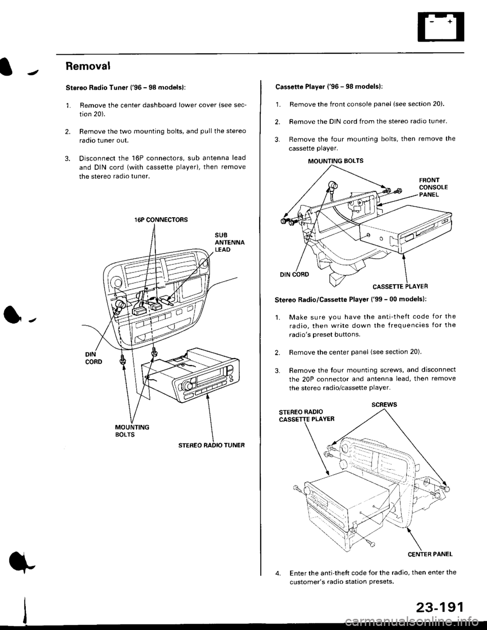
Removal
Stereo Radio Tuner ('96 - 98 modelsl:
3.
1.
2.
Remove the center dashboard lower cover (see sec-
tion 20).
Remove the two mounting bolts, and pullthe stereo
radao tuner out.
Disconnect the 16P connectors, sub antenna lead
and DIN cord (with cassette playerl, then remove
the stereo radio tuner.
16P CONNECTORS
1.
2.
Cassette Player ('96 - 98 modelsl:
Remove the front console panel (see section 20).
Remove the DIN cord from the stereo radio tuner.
Remove the four mounting bolts, then remove the
cassette player.
Stereo Radio/Cassette Player ('99 - 00 modelsl:
1. Make sure you have the anti-theft code for the
radio, then write down the frequencies for the
radio's oreset buttons.
Remove the center panel (see section 20).
Remove the four mounting screws, and disconnect
the 20P connector and antenna lead, then remove
the stereo radio/cassette player.
2.
3.
MOUNTING BOLTS
scREws
Enter the anti-theft code for the radio, then enter the
customer's radio station Presets.
23-191