1999 HONDA CIVIC pump belt
[x] Cancel search: pump beltPage 172 of 2189

Timing Belt
Removal
NOTE:
. Replace the timing belt at 105,000 mites (168,000 km)according to the maintenance schedule (normal con-ditions/severe conditions).
lf the vehicle is regularly driven in one or more of thefollowing conditions, replace the timing belt at 60,OOOmiles (U.S.A.) 100,000 km {Canada).. In very high temperatures (over 110"F, 43"C).. In very low temperatures (under -20.F, 29.C).. Turn the crankshaft pulley so the No. 1 piston is attop dead center (TDC) before removing the belt (seepage 6-57).
. Inspect the water pump before installing the timingbelt {see page 10-14).
1.
IOLER PULLEY BRACKETEOLT10 x 1.25 mm44 N.m 14.5 kgf.m, 33 bnft)
6-62
Remove the splash shield (see page 5-9).
Remove the adjusting bolt and mounting bolts, thenremove the power steering (P/S) pump belt andpump.
8xL25mm24 N m {2.{ kgf.m, 17 lbf.ft)
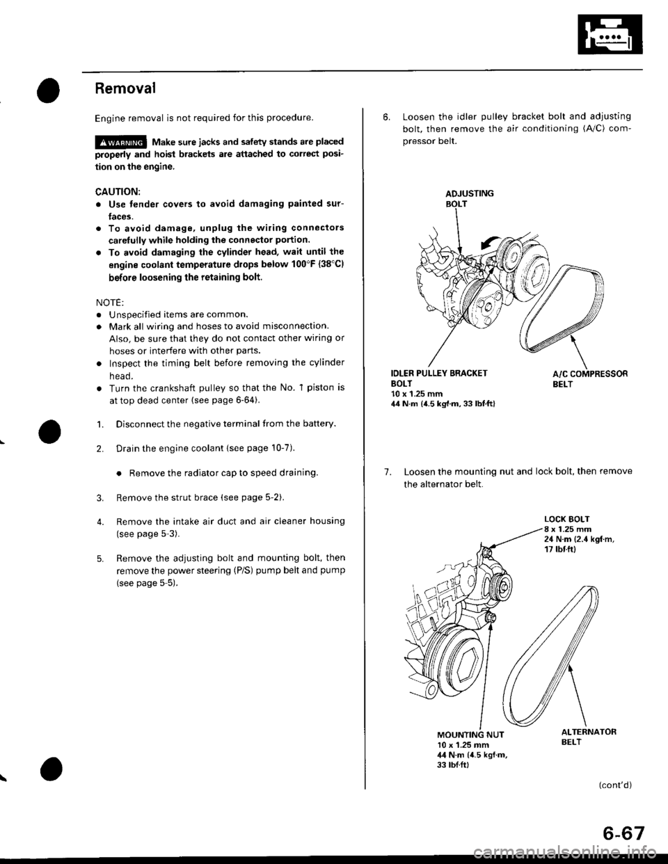
Loosen the idler pulley bracket bolt and adjusting bolt,then remove the air conditioning (A,/C) compressorbelt aDJUsnNG
44 N.m 14.5 kgt.m, 33 lbf.ft)
P/S PUMP LOWER ARACKET
a\
4. Loosen the mounting nut and lock bolt, then removethe alternator belt.
LOCK BOLT8 x 1.25 mm24 N.m {2.4 kgt.m.17 rb{.ftl
5. Remove the upper bracket (see page 6-69).
NOTE:
. Use a jack to support the engine before removingthe upper bracket.
o Place a cushion between the oil pan and the jack.
Remove the P/S pump lower bracket
8 x 1.25 mm24 N.m 12.,1 kgf.m,17 tbf.ftl
l0 x 1.25 mm
'-f'
MOUNTING10 x 1.25 mm44 N.m (4.5 kgf.m.33 rbf.fttBELT
HEAT SHIELD
Page 173 of 2189

7.
8.
Remove the crankshaft pulley (see page 6-59).
Remove the cylinder head cover'
NOTE: Refer to page 6-86 when installing the cylin-
der head cover.
Remove the middle cover and lower cover.
NOTE: Do not use the middle and lower covers for
storing removed items.
MIDDLE COVER
LOWER COVER
9.
10.Loosen the adjusting bolt 180'.
to remove tension from the
retighten the adjusting bolt.
9.8 N.m lt.o kgf m,
7.2lw'ftl
Push the tensioner
timing belt, then
N.m (5.5 kgt'm,
1 1. Remove the timing belt.
TDC
lnstallation
Install the timing belt in the reverse order of removal;
Only key points are described here.
1. Set the timing belt drive pulley so that the No. 1 pis'
ton is at top dead center (TDC). Align the groove on
the timing belt drive pulley to the V pointer on the
oil pumP.
set the camshaft pulleys so that the No. 1 piston is at
TDC.
Align the TDC marks on the intake and exhaust cam-
shaft pulleys.
MARK
(cont'd)
6-63
POINTER
Page 174 of 2189

Timing Belt
lnstallation (cont'dl
3. Install the timing belt tightly in the sequence shown.
@ Timing belt drive pulley (crankshaft) + @Adjusting pulley * @ Water pump pu ey + @ Intakecamshaft pulley + @ Exhaust camshaft pulley,
NOTE: Make sure the timing belt drive pulley andcamshaft pullevs are at TDC,
Loosen and retighten the adjusting bolt to tensionthe timing belt.
Install the lower cover and middle cover.
NOTE: Clean the middle and lower covers beforeinstalling.
Install the crankshaft pulley, then tighten the pulleybolt (see page 459).
Rotate the crankshaft pulley about five or six turnscounterclockwise so that the timing belt positions onthe pulleys.
Adjust the timing belt tension (see page A611.
7.
6-64
a
9. Check that the crankshaft pulley and camshaft pul-leys are both at TDC.
CRANKSHAFT PULLEY
CAMSHAFT PULLEY:
lf the camshaft and crankshaft pulleys are not posi-tioned at TDC, remove the timing belt, adjust theposition following the procedure on page &63, thenreinstall the timing belt.
After installation, adjust the tension of each belt.
. See section 23 for alternator belt tension adjust-ment.
. See section 22lor NC compressor belt tensionadiustment,
. See section 17 for P/S pump belt tension adjust-ment.
'l
10.
11.
I
"UP" MARKS
Page 177 of 2189

Removal
Engine removal is not required for this procedure.
!@@ Make sure jacks and safety stands are placed
properly and hoist brackels are attached to correst posi-
tion on the engine,
CAUTION:
o Use fender covers to avoid damaging painted sur-
faces.
To avoid damage, unplug the wiling connectors
carelully while holding the connector portion.
To avoid damaging the cylinder head, wait until the
engine coolant temperature drops below 100"F {38'Cl
before loosening the retaining bolt.
NOTE:
. Unspecified items are common.
. Mark all wiring and hoses to avoid misconnection.
AIso, be sure that they do not contact other wiring or
hoses or interfere with other parts.
o Inspect the timing belt before removing the cylinder
n eao.
. Turn the crankshaft pulley so that the No. 1 piston is
at top dead center (see page 6-64).
1. Disconnect the negative terminal from the battery.
Drain the engine coolant {see page 10-7).
. Remove the radiator cap to speed draining.
Remove the strut brace (see page 5-2).
Remove the intake air duct and air cleaner housing
(see page 5-3).
Remove the adjusting bolt and mounting bolt, then
remove the power steering (P/S) pump belt and pump
(see page 5 5).
2.
3.
4.
\
ADJUSTING
6. Loosen the idler pulley bracket bolt and adjusting
bolt, then remove the air conditioning (A/C) com-
pressor belt.
IDLER PULLEY BRACKETBOLT10 x 1.25 mm44 N.m {4.5 kg,l.m, 33 lbt.ft}
7. Loosen the mounting nut and lock bolt, then remove
the alternator belt.
LOCK BOLT8 x 1.25 mm24 N.m {2.4 kgf.m,17 tbtftl
ALTERNATORBELT10 x 1.25 mm,l,l N.m {4.5 kgf.m,33 tbf.ft,
(cont'd)
6-67
Page 239 of 2189

4.
Removal/lnspection/lnstallation
2.
3.
1.
5.
6.
1.
8.
Drain the engine oil.
Turn the crankshaft and align the white groove on
the crankshaft pulley with the pointer on the lower
cover.
Remove the cylinder head cover and upper cover'
Remove the power steering pump belt, air condi-
tioner beit and the alternator belt
Remove the crankshaft pulley and remove the lower
cover.
Remove the timing belt.
Remove the drive pulley.
Remove the oil pan and oil screen.
O.RINGReplaceOOWEL PIN
OIL SCREEN
9. Remove the oil PumP.
!'a
10.Remove the screws from the pump housing, then
separate the housing and cover'
Check the inner-to-outer rotor radial clearance on
the pump rotor. lf the inner-to outer rotor clearance
exceeds the service limit, replace the inner and
outer rotors.
lnner Rotor-to-Outer Rotor Radial Clearance
Standard {New}: 815A2 engine 0.04 - 0.16 mm
(0 002 - 0'006 in)
D16Y5, D16Y7, D16Y8 engines
0.02 - 0.14 mm 10.001 - 0.006 in)
Service Limit: 0.20 mm (0 008 inl
OUTER ROTOR
INNER ROTOR
Check the housing-to-rotor axial clearance on the
pump rotor. lf the housing-to rotor axial clearance
exceeds the service limit, replace the set of inner
and outer rotors and/or the pump housing
Housing-to-Rotor Axial Clearance
Standard (N€w): 816A2 engine 0.02 - 0.07 mm
(0.001 - 0.003 inl
D16Y5, D16Y7, D16Y8 engines
0.03 - 0.08 mm (0.001 - 0.003 inl
S€rvice Limit: 0.15 mm 10.006 in)
11.
't2.
(cont'd)
8-13
Page 269 of 2189

Water Pump
Inspection
't.
2.
Remove the timing belt (see section 6).
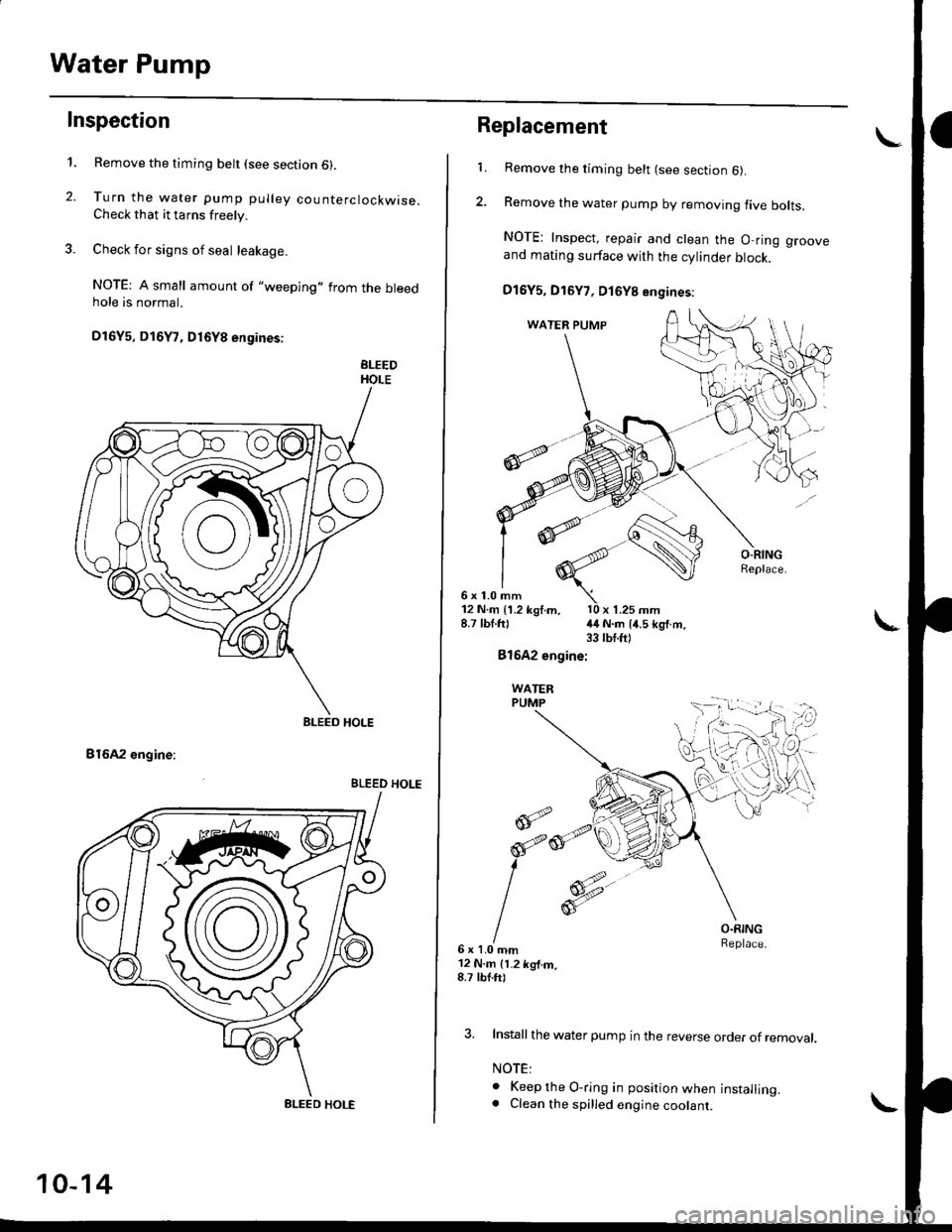
Turn the water pump pulley counterclockwise.Check that it tarns freely.
Check for signs of seal leakage.
NOTE: A small amount of "weeping,,from the bleedhole is normal.
Dl6Y5, Dl6Y7, D16Y8 engines:
BLEEDHOLE
B16A2 engine:
BLEED HOLE
BLEED HOLE
BLEED HOLE
10-14
Replacement
6x1.0mm
1.Remove the timing belt (see section 6).
Remove the water pump by removing five bolts.
NOTE: Inspect, repair and clean the O-ring grooveand mating surface with the cylinder block.
D16Y5, D16Y7, D16Y8 engines:
12 N.m {1.2 kgf.m, l0 x 1.25 mm8.7 lbt.ft) {4 N.m 14.5 kg{.m.33 tbt.ft)
Bl642 engine:
WATERPUMP
@;2
6x1.0mm12 N.m 11.2 kg{.m,8.7 tbf.ft)
O.RINGReplace.
3. Install the water pump in the reverse order of removal.
NOTE:
o Keep the O-ring in position when installing.. Clean the spilled engine coolant.
d
orp,
I
Page 873 of 2189

Description
The Continuously Variable Transmission (CVT) is an electronically controlled automatic transmission with drive and driv
en Oullevs, and a steel belt. The CVT provides non stage speeds forward and one reverse. The entire unit is positioned in
line with the engine.
Transmission
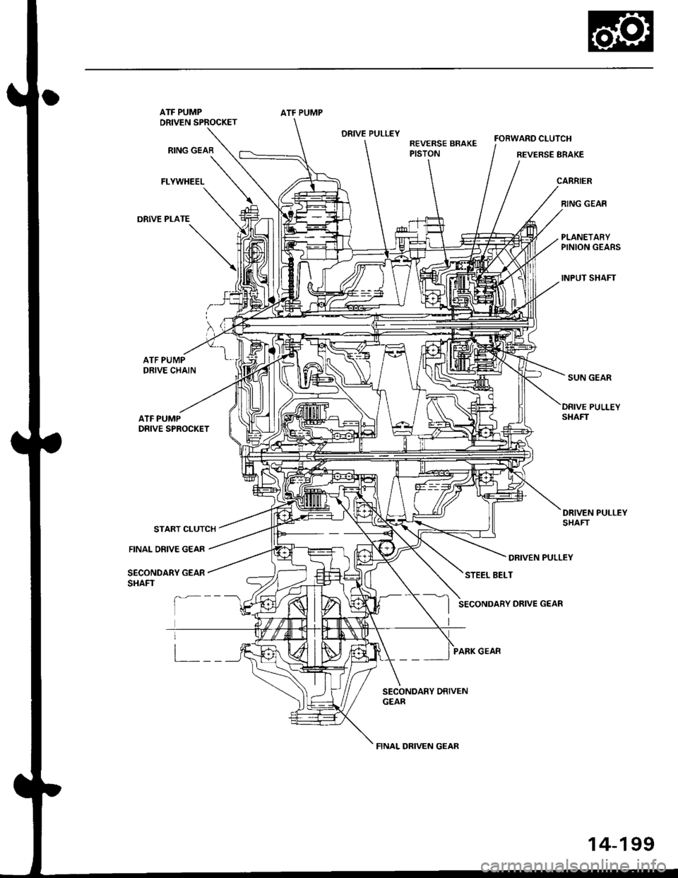
Around the outside of the flywheel is a ring gear which meshes with the starter pinion when the engine is being staned.
The transmission has four parallel shafts: the input shaft, the drive pulley shaft. the driven pulley shaft, and the secondary
gear shaft. The input shaft is in line with the engine crankshaft. The drive pulley shaft and the driven pulley shaft consist of
movable and fixed face pulleys. Both pulleys are linked by the steel belt.
The input shaft includes the sun gear. The drive pulley shaft includes the forward clutch which mounts the carrier assem-
bly on the forward clutch drum. The carrier assembly includes the pinion gears which mesh with the sun gear and the ring
gear. The ring gear has a hub-mounted reverse brake disc.
The driven pulley shaft includes the start clutch and the secondary drive gear which is integral with the park gear' The sec-
ondary gear shaft is positioned between the secondary drive gear and the final driven gear. The secondary gear shaft
includes the secondary driven gear which serves to change the rotation direction. because the drive pulley shaft and the
driven oullev shaft rotate the same direction. When certain combinations of planetary gears in the transmission are
engaged by the clutches and the reverse brake, power is transmitted from the drive pulley shaft to the driven pulley shaft
to provide E, E, E, and El.
Electronic Control'96 - 98 Models:
The electronic control system consists of the Transmission Control Module (TCM), sensors, three linear solenoids, and a
inhibitor solenoid. Shifting is electronically controlled under all conditions'
The TCM is located below the dashboard, behind the kick panel on the driver's side.'99 - 00 Models:
The electronic control svstem consists of a Powertrain Control Module (PCM), sensors, three linear solenoids and an
inhibitor solenoid. Shifting is electronically controlled under all conditions. A Grade Logic Control System to control shift-
ing in E position while the vehicle is ascending or descending a slope.
The PCM is located below the dashboard, under the kick panel on the passenger's side.
Hydraulic Control
The lower valve body assembly includes the main valve body, the Pressure Low (PL) reguiator valve body, the shift valve
body, the start clutch control valve body, and the secondary valve body. They are positioned on the lower part of the
transmission housing.
The main valve body contains the Pressure High (PH) control valve, the lubrication valve, and the pitot regulator valve.
The secondary valve body contains the PH regulator valve, the clutch reducing valve, the start clutch valve accumulator,
and the shift inhibitor valve. The PL regulator valve body contains the PL regulator valve and the PH-PL control valve
which is ioined to the PH,PL control linear solenoid. The inhibitor solenoid valve is bolted on the PL regulator valve body.
The shift valve body contains the shift valve and the shift control valve. which is joined to the shift control linear solenoid.
The start clutch control valve body contains the start clutch control valve, which is joined to the start clutch control linear
solenoid. The linear solenoids and the inhibitor solenoid are controlled by the TCM or PCM. The manual valve body which
contains the manual valve and the reverse inhibitor valve, is bolted on the intermediate housing.
The ATF pump assembly is located on the transmission housing, and is linked with the input shaft by the sprockets and
the sprocket chain. The pulleys and the clutch receive fluid from their respective feed pipes, and the reverse brake receives
fluid from internal hydraulic circuit.
Shift Control Mechanism
Input from various sensors located throughout the vehicle determines which linear solenoid the TCM or PCM will activate.
Activating the shift control linear solenoid changes the shift control valve pressure, causing the shift valve to move. This
pressurizes the drive pulley pressure to the drive pulley and the driven pulley pressure to the driven pulley and changes
their effective pulley ratio. Activating the start clutch control linear solenoid moves the start clutch control valve. The start
clutch control valve uncovers the port, providing pressure to the start clutch to engage it(cont'd)
14-195
,!
Page 877 of 2189

ATF PUMPDRIVEN SPROCKET
RING GEAR
FLYWHEEL
DRIVE PLATE
ATF PUMP
DRIVE PULLEYREVERSE BRAKEPISTON
FORWARD CLUTCH
BEVERSE BRAKE
CARRIER
RING GEAR
PLANETARYPINION GEARS
INPUT SHAFT
ATF PUMPDRIVE CHAIN
ATF PUMPDRIVE SPROCKET
START CLUTCH
DRIVEN PULLEY
STEEL BELT
SECONDARY DRIVE GEAR
PARK GEAR
DRIVEN PULLEYSHAFT
FINAL DRIVE GEAR
SECONDARY GEARSHAFT
a--
i___
il
14-199