1999 HONDA CIVIC piston pin
[x] Cancel search: piston pinPage 199 of 2189
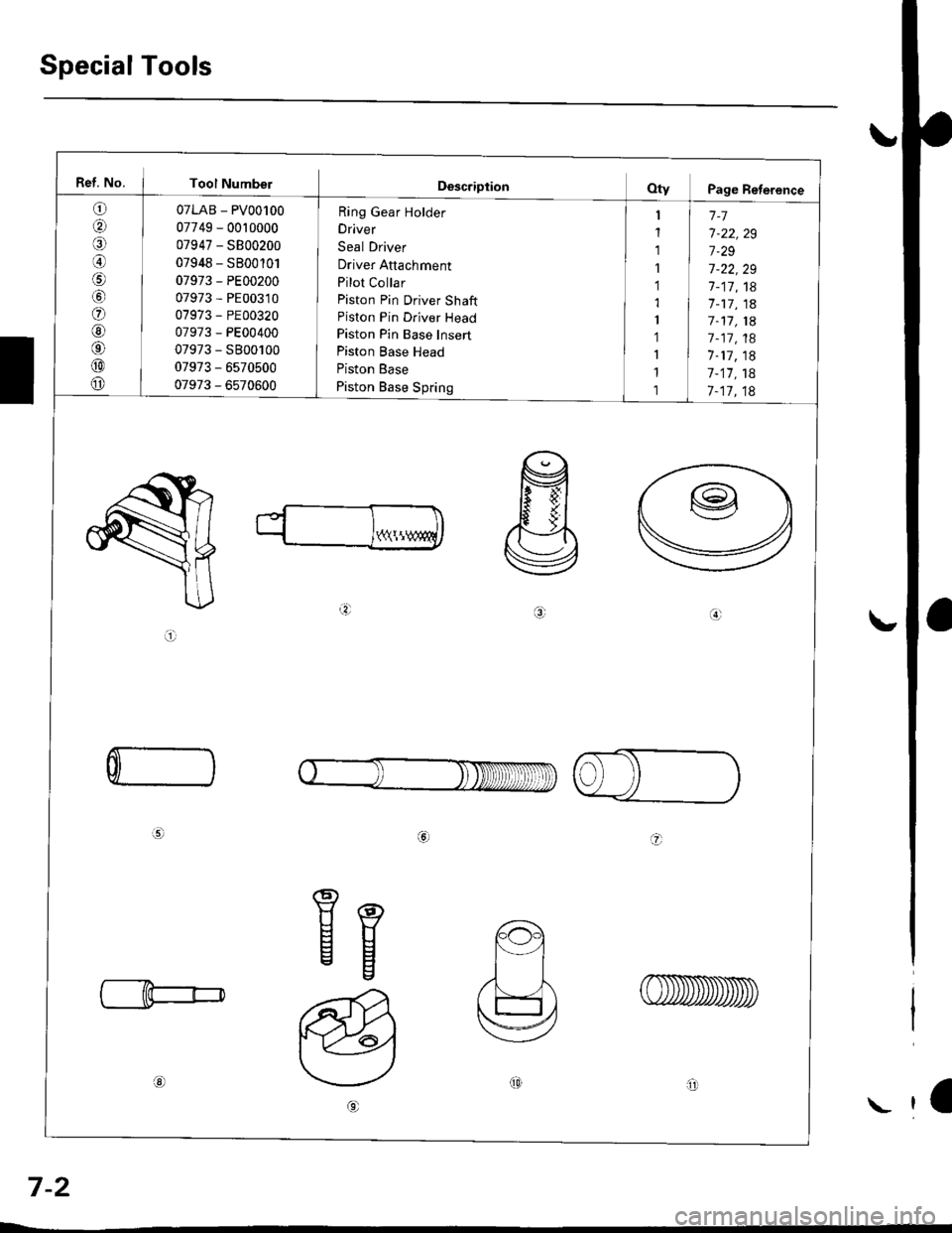
Special Tools
Ref. No. I Tool Numbel
o
aal
@
o
@6'
@
o
07LAB - PV00100
07749 - 0010000
07947 - SB00200
07948 - SB00'101
07973 - PE00200
07973 - PE00310
07973 - PE00320
07973 - PE00400
07973 - S800100
07973 - 6s70500
07973 - 6570600
Ring Gear Holder
Driver
Seal Driver
Driver Attachment
Pilot Collar
Piston Pin Driver Shaft
Piston Pin Driver Head
Piston Pin Base Insert
Piston Base Head
Piston Base
Piston Base Spring
1-7
7-22,29
7.29
7-22,29
7-17,18'7 -17, 1a
7-11, 1A
7 -17, 18
1-17, 18
7-17,18
7-17,18
Y(\!
a.:
ai
C
a
Eg
ot0arll
a
7-2
\
Page 203 of 2189

lllustrated Index
(cont'd)
NOTE: New rod bearings must be selected by matching connecting rod assembly and crankshaft(see page 7,11).identification markings
Lubricate all internal parts with engine oil duringreassembtv.
PISTON INSTALLATION DIRECTION:
EXHAUST
4\/=\6\z\
\e/!rqrf/
INTAKE
PISTON RINGSReplacement. page 7-20Measurement, pages 7 20 andj-21Alignment, page 7-21
PISTON PINRemoval, page 7,17Installation, page 7-18Inspection, page 7,19
CONNECTING RODEnd play, page 7-8Selection, page 7,18
CONNECTING RODBEARINGSClearance, page 7 11Selection, page 7-11
CONNECTING ROD BEARING CAPInstallation, page 7-23NOTE: lnstall caps so thebearing recess is on thesame side as the recessin the rod.
PISTONInspectron, page 7-15NOTE: Betore removing the piston, inspect thetop of the cylinder bore for carbon build-up orridge. Bemove ridge if necessary, page 7-13
ENGINE BLOCKCylinder bore inspection, page 7-16Warpage inspection, page 7,'16Cylinder bore honing, page 7,17
Inspect top of each cylinder borefor carbon build-up or ridgebefore removing piston.Remove ridge if necessary, page 7-13
CONNECTING ROD CAP NUT816A2 €ngin6:9 x 0.75 mm{0 N.m (4.1 kgt m, 30 tbf.ftlD16Y5, Dl6Y7. D16Y8 engines:8 x 0.75 mm3l N.m {3.2 kg{.m,23 tbt.fr)Apply engine oiltothe bolt threads.NOTE: After torquing each bearingcap, rotate crankshaft tocheck for binding.
7-6
Page 214 of 2189
Cylinder BlockPiston Pins
Bore Honing
1.Measure cylinder bores as shown on page 7-16. lf the
block is to be reused, hone the cylinders and remea-
sure the bores.
Hone cylinder bores with honing oil 8nd a fine (400
grit) stone in a 60 degree cross-hatch pattern.
NOTE:
. Use only a rigid hone with 400 grit or finer stone
such as Sunnen, Ammco, or equivalent.
. Do not use stones lhat are worn or broken.
When honing is complete, thoroughly clean the
engine block of all metal particles. Wash the cylin-
der bores with hot soapY water, then dry and oil
immediately to prevent rusting.
NOTE: Never use solvent. it will only redistribute the
grit on the cylinder walls.
lf scoring or scratches are still present in cylinder
bores after honing to the service limit, rebore the
cylinder block.
NOTE: Some light vertical scoring and scratching is
acceptable if it is not deep enough to catch your fin-
gernail and does not run the full length of the bore.
CYLINOES BLOCK
CYLINDER
NOTE:
. After honing, clean the cylinder thoroughly with
soapy warer.
. Onlv a scored or scratched cylinder bore must be
noneo.
Removal
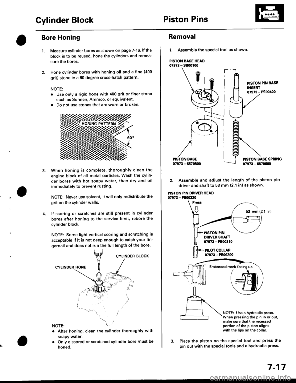
l. Assemble the special tool as shown.
PISTON BASE HEAD07973 - SBtx)too
ft
PISTON PIN BASE
INSERT01973 - PE00'0)
ptn
NOTEi Us6 a hydraulic press.When pressing the pin in or out.make sure that the recesssdportion of the piston alignswith the lips on the collar.
rg
g\
lj*N*,""
2. Assemble and adjust the length of the piston
driver and shaft to 53 mm (2.1 inl as shown.
PISTON PIN DRIVER HEAD07973 - PE00320
Proat
0
PISTON PINDRIVER SHAFT0t973 - PEqr310
PILOT COLLAR07973 - PE00200
3. Place the piston on the sp€cial tool and press the
pin out with the special tools and a hydraulic press.
Emboss6d mark facing up
7-17
Page 215 of 2189
Connecting RodsPiston Pins
Selection
Each rod falls into one of four tolerance ranges {from O to+ 0.024 mm (0 to + 0.0009 in), in 0.006 mm (0.0002 in)increments) depending on the size of its big end bore. lt,sthen stamped with a number {1, 2,3, or 4) indicating therange.
You may find any combination ot l, 2, 3, or 4 in any
engrne.
Normal Eore Size: 48.0 mm (1.89 in)
NOTE:
o Reference numbers are for big end bore size and doNOT indicate the position of the rod in the engine.. Inspect connecting rod for cracks and heat damage.
CONNECTING ROD AOREREFERENCE NUMBERHalf of number is stamped onbearing cap, the other half onconnectrng rod.
7-18
Installation
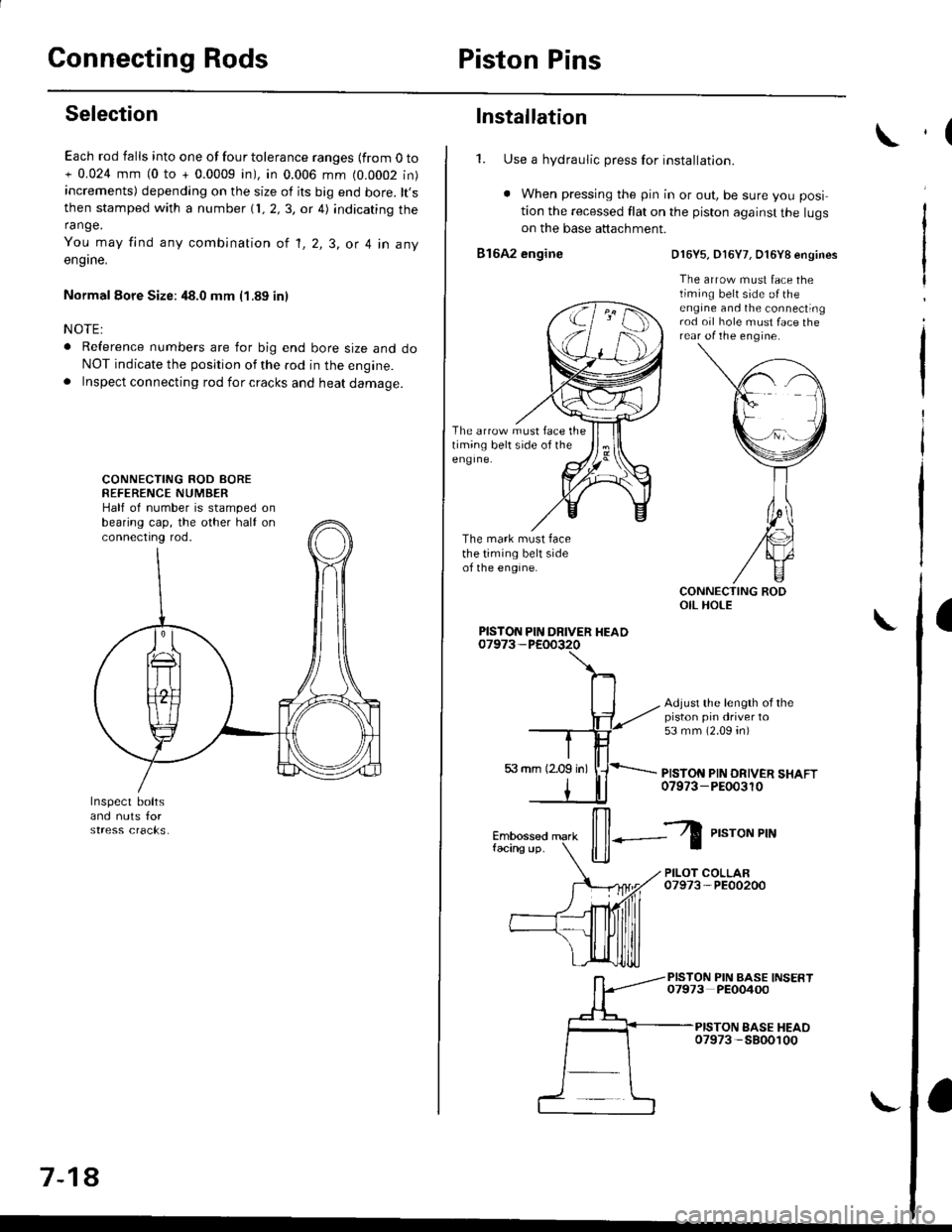
1. Use a hydraulic press for installation.
. When pressing the pin in or out, be sure you posi
tion the recessed flat on the piston against the lugson the base attachment.
816A2 engine
The arrow must face thetiming belt side of theeng Ine.
The mark must facethe timing belt sideof the engine.
D16Y5, D16Y7, O16Y8 engines
The arrow must face thetiming belt side o{ theengine and the connectingrod oil hole must face therear of the engine.
Adjust the length of thepiston pin driver to53 mm (2.09 4n)
PISTON PIN DRIVER SHAFT07973-PEOo3r0
PISTON PIN DRIVER HEAD
il--Z
P,"roNPrN
PILOT COLLAR07973-PE00200
PISTON PIN BASE INSERT07973 PEO0400
PISTON EASE HEAO07973 -5800100
,(
a
Page 216 of 2189
lnspection
1.
Oversize:
Oversize:
NOTE; All replacement piston pins are overslze.
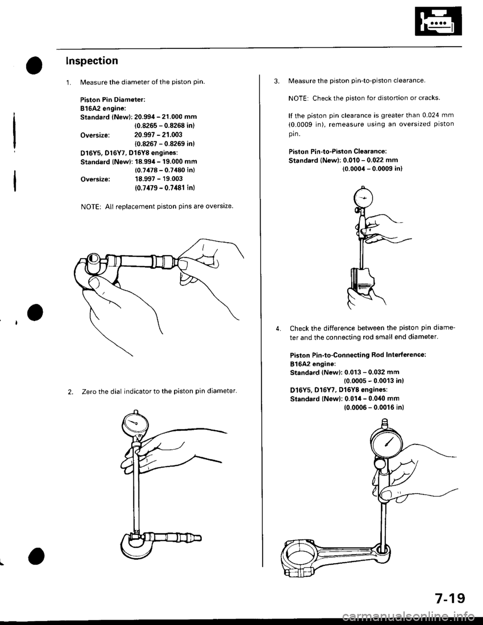
2. Zero the dial indicator to the piston pin diameter'
Measure the diameter of the piston pin.
Piston Pin Diametel:
B16A2 engine:
Standard {New): 20.994 - 21.000 mm
(0.8265 - 0.8268 in)
20.997 - 21.003
10.8267 - 0.8269 inl
D16Y5, Dl6Y7, Dl6YB engines:
Standard lNewl: 18.99,1- 19.000 mm
(0.7478 - 0.7480 inl
18.997 - 19.003
{0.7479 - 0.7481 in)
3. Measure the piston pin-to-piston clearance.
NOTE: Check the piston for distortion or cracks.
lf the piston pin clearance is greater than 0.024 mm
(0.0009 jn), remeasure using an oversized piston
pin.
Piston Pin-to-Piston Clearance:
Standard (New): 0.010 - 0.022 mm
(0.0004 - 0.0009 in)
Check the difference between the piston pin diame-
ter and the connecting rod small end diameter'
Piston Pin-to-Connesting Rod Interterence:
816A2 engine:
Standard (New): 0.013 - 0.032 mm(0.0005 - 0.0013 in)
D16Y5, D16Y7, Dl6YB engines:
Siandard lNewl; 0.014 - 0.040 mm
4.
10.0006 - 0.0016 inl
7-19
Page 219 of 2189

Piston RingsCrankshaft Oil Seal
Alignment (cont'dl
TOP RING ---.>
SECOND RING >
MARK
,a-)
/\_4
o,.r^o( qffi<--sPACER
\Z-.
v
Rotate the rings in their grooves to make sure theydo not bind.
Position the ring end gaps as shown:
DO NOT position any ring gapat piston thrust surfaces.
DO NOT position any ring gapin line with the piston pin hole.OIL RING GAP
SECOND RING GAP
Approx.90
TOP RING GAP
7-22
Installation
The seal surface on the block should be dry.Apply a light coat of oil to the c.ankshaft and tothe lip of the seal.
1. Drive the crankshaft oil seal squarely into the right
side cover using the special tools.
HANDLE DRIVER07749 0010000
seal with thepan number sidefacing out.
Confirm that the clearance is equal all the way
around with a feeler gauge.
Clearance:0.5 - 0.8 mm (0.02 - 0.03 inl
NOTE: Refer to page 8-14 for installation of the oilpumo side crankshaft oil seal.
,(
\
Page 681 of 2189

Description
The automatic transmission is a 3-element torque converter and a dual-shaft electronically controlled unit which provides
4 soeeds forward and 1 reverse.
Torque Convertel, Geats, and Clutches
The torque converter consists of a pump, turbine and stator, assembled in a single unit. They are connected to the engine
crankshaft so they turn together as a unit as the engine turns. Around the outside of the torque converter is a ring gear
which meshes with the starter pinion when the engine is being started. The entire torque converter assembly seryes as a
flywheel while transmiuing power to the transmission mainshaft.
The transmission has two parallel shafts: the mainshaft and the countershaft. The mainshaft is in Iine with the engine
crankshaft. The mainshaft includes the 1st, 2nd and 4th clutches, gears tor 2nd, 4th, reverse and lst (3rd gear is integral
with the mainshaft, while the reverse gear is integral with the 4th gear). The countershaft includes the 3rd clutch, and
gears for 3rd,2nd, 4th, reverse. 1st and park. The gears on the mainshaft are in constant mesh with those on the counter-
shaft. When certain combinations of gears in transmission are engaged by clutches. power is transmitted from the main-
shaft to the countershaft to provide E, ld, E, and E positions.
Electronic Control
The electronic control svstem consists of the Powertrain Control Module {PCM), sensors, a linear solenoid and four
solenojd valves. Shifting and lock-up are electronically controlled for comtonable driving under all conditions. The PCM is
located below the dashboard, under the front lower panel on the passenger's side
Hydraulic Control
The valve bodies include the main vatve body, the secondary valve body, the regulator valve body, the servo body and the
lock-up valve body through the respective separator plates, They are bolted on the torque converter housang
The main valve body contains the manual valve, the 1-2 shift valve. the 2nd orifice control valve, the CPB {Clutch Pressure
Back-up) valve, the modulator valve. the servo control valve, the relief valve, and ATF pump gears The secondary valve
body contains the 2-3 shift valve. the 3-4 shift valve, the 3-4 orifice control valve, the 4th exhaust valve and the CPC (Clutch
pressure Control) valve. The regulator valve body contains the pressure regulator valve, the torque converter check valve,
the cooler relief valve, and the lock-up control valve. The servo body contains the servo valve which is integrated with the
reverse shift fork, and the accumulators. The lock-up valve body contains the lock-up shift valve and the lock-up timing
valve. The linear solenoid and the shift control solenoid valve Ay'B are bolted on the outside of the transmission housing,
and the lock-up control solenoid valve Ay'B is bolted on the outside of the torque converter housing. Fluid from regulator
passes through the manual valve to the various control valves. The clutches receive fluid from their respective teed pipes
or internal hydraulic circuit.
Shift Control Mechanism
Input from various sensors located throughout the car determines which shift control solenoid valve the PCM will activate
Activating a shift control solenoid valve changes modulator pressure, causing a shift valve to move. This pressurizes a line
to one of the clutches, engaging that clutch and its corresponding gear, The shift control solenoid valves A and B are con-
trolled by the PCM.
Lock-up Mechanism
In ,Dt1 position, in 3rd and 4th. and in E position in 3rd, pressurized fluid is drained from the back of the torque converter
through a fluid passage, causing the lock-up piston to be held against the torque converter cover. As this takes place, the
mainshaft rotates at the same as the engine crankshaft. Together with hydraulic control, the PCM optimizes the timing of
the lock-up mechanism. The lock-up valves control the range of lock-up according to lock-up control solenoid valves A and
B, and linear solenoid. When lock-up control solenoid valves A and B activate, the modulator pressure changes The lock-
up control solenoid valves A and B and the linear solenoid are controlled by the PCM.
(cont'd)
14-3
Page 682 of 2189
Description
(cont'dl
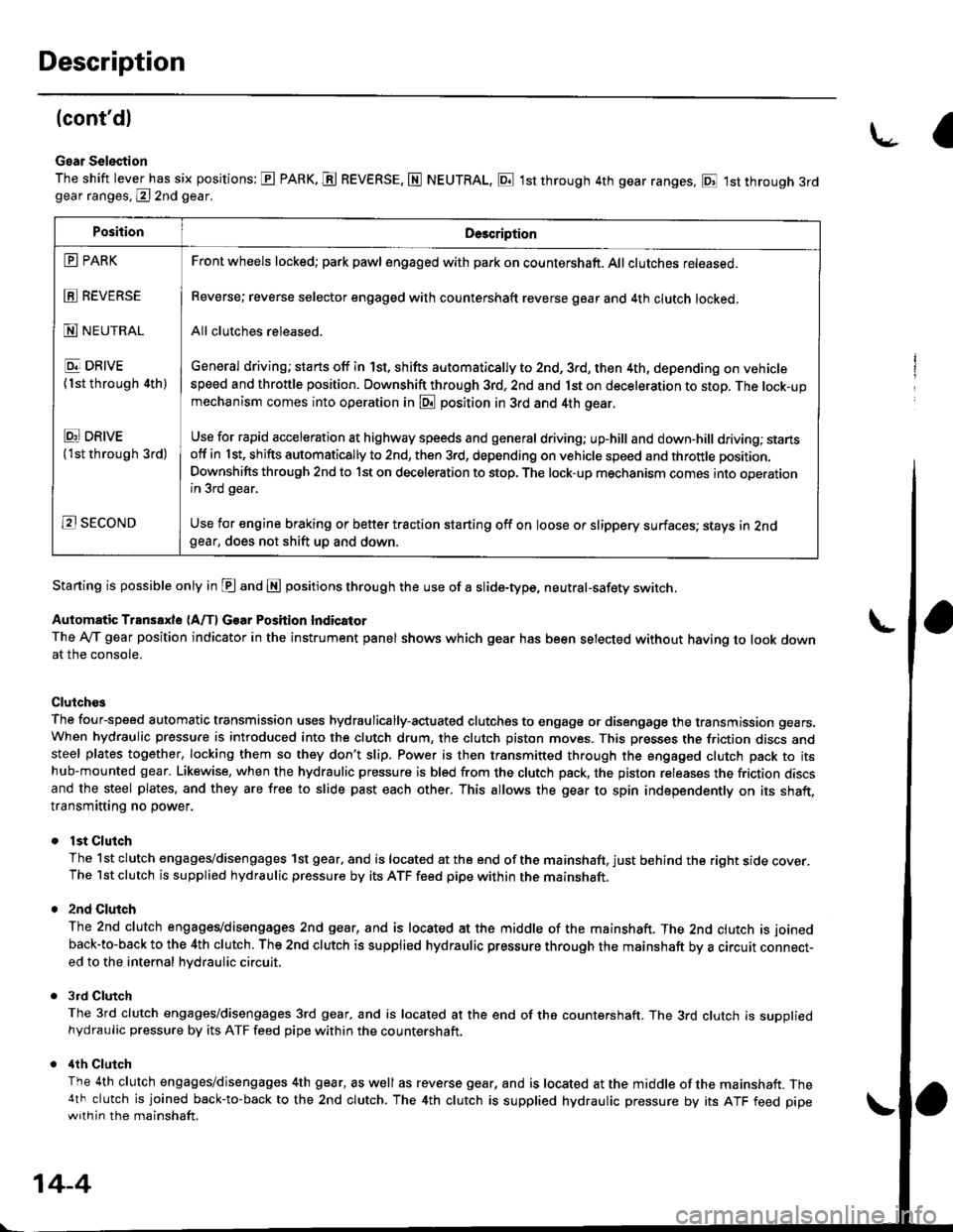
Gear Selection
The shift lever has six positions: E PARK. E REVERSE, N NEUTRAL, E 1st through 4th gear ranges, E 1st through 3rdgear ranges, @ 2nd gear.
Starting is possible only in E and E positions through the use of a slide-type, neutral-safety switch.
Automatic Transaxle (A/f, Gear Position Indicator
The Ay'T gear position indicator in the instrument panel shows which gear has been selected without having to look downat the console.
Clutch€s
The four-speed automatic transmission uses hydraulically-actuated clutches to engage or disengage the transmission gears.When hydraulic pressure is introduced into the clutch drum, the clutch piston moves. This presses the friction discs andsteel plates together, locking them so they don't slip. Power is then transmitted through the engaged clutch pack to itshub-mounted gear. Likewise, when the hydraulic pressure is bled from the clutch pack, the piston releases the friction discsand the steel plates, and they are free to slide past each other. This allows the gear to spin independently on its shaft,transmitting no power.
lst Clutch
The 1st clutch engages/disengages 1st gear, and is located at the end of the mainshaft, just behind the right sroe cover.The 1st clutch is supplied hydraulic pressure by its ATF feed pipe within the mainshaft.
2nd Clulch
The 2nd clutch engagegdisengages 2nd gear, and is located at the middle of the mainshaft. The 2nd clutch is joined
back-to-back to the 4th clutch. The 2nd clutch is supplied hydraulic pressure through the mainshaft by a circutr connect-ed to the internal hvdraulic circuit,
3rd Clutch
The 3rd clutch engages/disengages 3rd gear, and is located at the end of the countershaft. The 3rd clutch is suooliedhydraulic pressure by its ATF feed pipe within the countershaft.
ilth Clutch
The 4th clutch engages/disengages 4th gear, as well as reverse gear, and is located at the middle of the mainshaft. The4th clutch is joined back-to-back to the 2nd clutch. The 4th clutch is supplied hydraulic pressure by its ATF feed pipewith in the mainshaft.
\-a
PositionDe3cription
E PARK
E REVERSE
N NEUTRAL
E DRIVE
{1st through 4th)
Ei DRtvE('lst through 3rd)
B SECOND
Front wheels locked; park pawl engaged with pa* on countershaft. All clutches released.
Reverse; reverse selector engaged with countershaft reverse gear and 4th clutch locked.
All clutches released.
General driving; starts off in 1st, shifts automatically to 2nd, 3rd, then 4th, depending on vehiclespeed and throttle position. Downshift through 3rd, 2nd and 1st on deceleration to stop. The lock-upmechanism comes into operation in @ position in 3rd and 4th gear.
Use for rapid acceleration at highway speeds and general driving; up-hill and down,hill dfiving; stansotf in 1st, shifts automatically to 2nd, then 3rd, depending on vehicle speed and throttle position.
Downshifts through 2nd to lst on deceleration to stop. The lock-up mechanism comes into operationin 3rd gear,
Use for engine braking or better traction starting off on loose or slippery surfaces; stays in 2ndgear, does not shift up and down.
14-4