1999 HONDA CIVIC integrated control unit
[x] Cancel search: integrated control unitPage 1817 of 2189

Contents
How to Use This Manual ICircuit Schematics (see Circuit Index)Fuse/Relaylnformation 6Ground-to-Componentslndex 6-6ComponentLocationPhotooraohs 201Conriector Views 202
Circuit Index
Accessory power socket 155Air conditionerAir delivery'96198 models 61'99-'00 models 61-2Blower controls'96198 models 60'99100 models 60-1Compressor controls 62Fans 63Anti-lock brake system (ABS) 44A/T gear position indicatorCVT 89All except CVT 89-1Automatic transmission controlsAll '96-'98 models except CVT and GX 39All '99100 models except CVT 39-8All GX models 39-8'96-'�98 CVT 39-4'99100 cw 39-12Back-up lightsCoupe and Sedan 110Hatchback l'10-1Brake lightsAll Coupes and'96-'98 Sedans 110-15'99-'00 Sedans 110-16Hatchback 110-17Brake system indicator light'96198 models 7'1'99100 models 71-1Ceiling light 114-3Charging system 22Condenser fan 63Console lights 114Cruise control 34Dash lights 114Daytime running lights 110- 13Engine coolant temperature gauge 81-1Fog lights 110-10Front parking lights 110-2Fuel gauge 81-1Fuse/relay boxUnder-dash 6Under-hood 6-4Underhood ABS 6-3Gauges 81Ground distribution 14Ground-to-Componentslndex 6-6Hazard warning lightsAll except '99100 Sedans 110-6'99100 Sedans 110-8Headlights 110-12Headlight switch 100Heater - See Air ConditionerHorn'96197 models 40'98 model 40-1'99100 models 40-2lgnition key reminder 73lgnition systemAll '96198 models except Dl685 20All '99100 models except D16Y5 with Mn 2O-2All D1685 engines 20-2'99-'00 D 16Y5 with M/T 20
lndicators 80Integrated control unit 70lnterlock systemAll except'96J98 CVT 138'96198CVT 138-1License plate lightsAll Coupes and '96-'98 Sedans I l0-3'99100 Sedans 1 10-4Hatchback 110-5Low fuel indicator light 74Moonrool'96197 models |22'98-'00 models 122-1Odometer 81Oil pressure indicator light 80-3Power distributionBattery to ignition switch, fuses, and relaysFuses to relays and components 10-2Power door locksAll models without keyless entry 130'96-'98 models with keyless entry 130-2'99100 models with keyless entry 130-12Power mirrorsWithout detogger 141With defogger '141-2
Power windows 120Programmed fuel injection system (PGNr-Fl)All '96-98 models except D1685 23All '99-'00 models except D16Y5with M/T and D1685 24All D1685 engines 25'99100 D16Y5 with M/T 23Radiator fan 63Rear window defogger'96-,98 models 64'99100 models 64-1Seat belt reminder 73Security system'96.'98 USA HX, LX, EX 133'96-'98 Canada EX, Si 133'99TOO USA HX, LX, EX, DX.V Si 133-4'99100 Canada EX, Si 133-4All CX and DX models 133-8Speedometer 81Starting systemA./T (All except Dl685) 21A"/r (D16Bs) 21-1Manualtransmission 21-2Slereo sound system 150Supplemental rastraint system (SRS) 47Tachometer 81TailliqhtsAllboupes and'96-'98 Sedans 110-3'99100 Sedans 1 10-4Hatchback 110-5Trunk light 114-3Turn signal lightsAll except'99100 Sedans 110-6'99-'00 Sedans 1 10-8Vehicle speed sensor (VSS) 33Wiper/washerFront 91Rear 92
10
Page 1834 of 2189
![HONDA CIVIC 1999 6.G Workshop Manual Fuse/Relay Information
- Under-dash Fuse/Relay Box
Front View
c712(To moonroof wire harness)
. : Canadai : Not UsedO : C926 loprion (+B)l
@ : C927 loption (dash lights)]
O : C928 [Option (ACC]I
@ : C9 HONDA CIVIC 1999 6.G Workshop Manual Fuse/Relay Information
- Under-dash Fuse/Relay Box
Front View
c712(To moonroof wire harness)
. : Canadai : Not UsedO : C926 loprion (+B)l
@ : C927 loption (dash lights)]
O : C928 [Option (ACC]I
@ : C9](/manual-img/13/6068/w960_6068-1833.png)
Fuse/Relay Information
- Under-dash Fuse/Relay Box
Front View
c712(To moonroof wire harness)
. : Canadai : Not UsedO : C926 loprion (+B)l
@ : C927 loption (dash lights)]
O : C928 [Option (ACC]I
@ : C929 loption (lc2)l
Rear View
css2
c421(To main wire harness)
c801CI-o SRS main harness)
c501(To dashboard wire harness)
^ : Not used ('96-'97 models)
c913(To ignition switch)
INTEGRATEDCONTROL UNITCONNECTOR A
c419Oo main wire harness)
REAR WINDOWDEFOGGER RELAY
TURN SIGNAUHAZARD RELAY
c423(To main wire harness)
co
c422(To main wire harness)
POWERwtNDowRELAY
c551flo lloor wire harness)c439 f96.'97 MODELSand ALL GX MOOELS)(To main wire harness)
T1 T-t T"l T"t r-r r-'l T1 F n r-l r-l r'123 24 25 26 27 28 29 30 31 32 33I-J I.J I.J IJ IJ IJ LJ IJ IJ I.J I.J I-I
r"1 r-t r-t T-l r"l r-r Fl r:1 n rJ n -12 13 14 t5 16 17 t8 19 2A 2t 22LI I.J L! LI tJ LJ (J LI IJ IJ T-I I.J
n r:l rj.l |-l T"l Tl r:t n r-l |;.l r-r r-l1 2 3 4 5 6 7 I 9 10 11LI LI IJ LJ LJ I,J T-I I.J TJ IJ I.-I tJ
c420(To main wire harness)
6
(To floor wire harness)
Page 1840 of 2189

Ground-to-Components I ndex
f.,lONOTE: All ground wires are BLK unless otherwise noted.
GroundPageComponents or Circuit Grounded
Battery (BLKYEL)
Steering pump bracket
t+-rg ITransmission housing
l
G101
(-1)
G101
(-2)
14-2
and
14-3
ano
14-1
Powertrain or engine control module (PG1 and pG2 are BLK: LG1 and LG2 are
BRN/BLK), EGR control solenoid valve (CW, EGR valve and lift sensor (Dt6yS enginewith M,/T), Engine coolant temperature switch, pGM-Fl main relay, power steeringpressure switch (USA), Primary HO2S (D16Y5 engine with l\/,/T), Vehicle speed sensor,VTEC pressure switch (D16Y5/D16Y8 engines), CKF sensor (BRN/BLK), Transmission
control module (CYf) (Pc1 is BLK: LG1 is BRN/BLK)
Shielding betvveen the PCM or ECM and these components (all have BRN/BLK wires):
CKF sensor, TDC/CKP/CYP sensor. Primary and secondary heated oxygen sensors.
Knock sensor (CWDl6YB engine), Mainshaft speed sensor (AiT except CVT),
I Countershaft speed sensor (A/T except CVf)
Shielding between the TCM and these components (CVT) (all have BRN/BLK wires):
Drive pulley speed sensor, Driven pulley speed sensor, Secondary gear shaft
speed sensor
Powertrain or engine control module (PG1 and pG2 are BLK; LG1 and LGz are
BRN/BLK), EGR control solenoid valve (D16Y5 engine), EGR valve (Dt685), Engine
coolant temperature switch, Fuel pressure regulator shut-off solenoid valve (D1685),
PGM-FI main relay, Power steering pressure switch (USA), Vehicle speed sensor, VTECpressure switch (All except D16Y7 engine), CKF sensor (A
except 81642) (BRN/BLK)
Shielding between the PCM or ECM and these components (all have BRN/BLK wires):
CKF sensor, TDC/CKP/CYP sensor, Primary and secondary heated oxygen sensors,
Knock sensor (All except D16Y7 engine), i/ainshaft speed sensor (Arf except CW),
Countershaft speed sensor (A,/T except CVf), Drive pulley speed sensor (CW), Drivenpulley speed sensor (CVT), Secondary gear shaft speed sensor (CVf)
I Badiator fan motor, Right front parking/turn signat tight, Right headtight
G20214-4I Cruise control actuator, Left front parking/turn signal lights, Left headlight, Rear window
I washer motor, Windshield washer motor, Washer fluid level switch (,99-'00 Canada)
G401| +-o
and
14-7
Accessory power socket, Brake fluid level switch, Clutch interlock switch (M/T), Clutchswitch (lillT with cruise/D16Y5 engine with MfD, Combination wiper switch (Z wires),
Cruise control main switch, Cruise control unit, Dash lights brightness controller, Data
link connector, Daytime running lights control unit (Canada), Gauge assembly, Horn('96-'97 models), Integrated control unit, Interlock control unit (ArI), Keyless door lock
control unit ('99-'00 models with keyless), Moonroof close and open relays, Moonroof
switch, Park pin switch (A/r), Power window relay, Rear window defogger relay, Rear
window defogger switch ('96-'98 models), Steering lock, Stereo radio tuner (,96-,98
USA: LX, EX, and HX), Turn signal/hazard relay, Windshield wiper motor.....plus
everything grounded through G402
6-6
Page 1965 of 2189
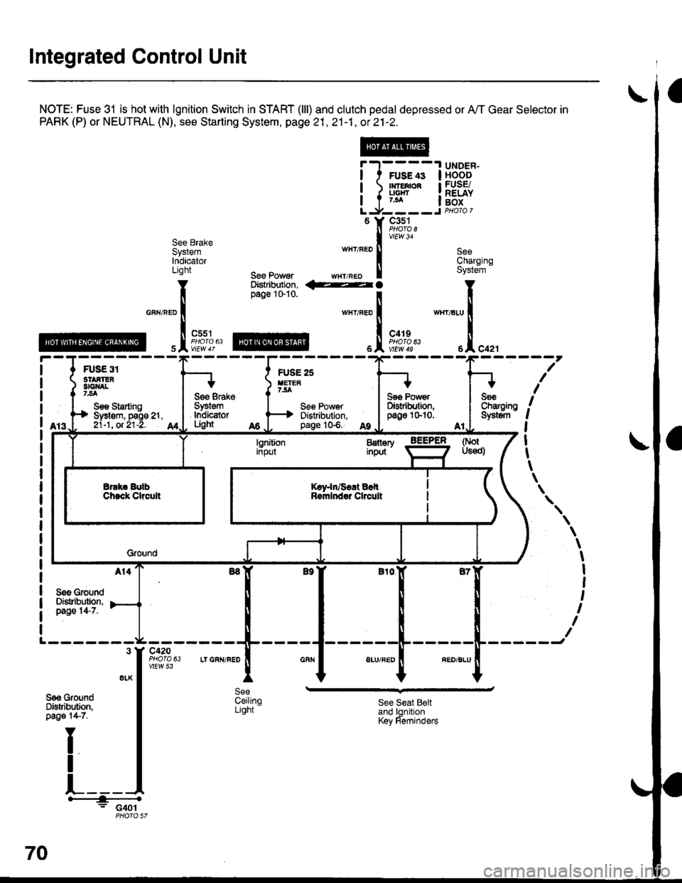
Integrated Control Unit
NOTE: Fuse 31 is hot with lgnition Switch in START (lll) and clutch pedal depressed or A,/T Gear Selector in
PARK (P) or NEUTRAL (N), see Starting System, page 21,21-1, ot 21-2.
See BrakeSystemlndicatorli^hl
FUSE 3IstaaTEaSIGI{AT7AAI
I
I
I
I
I
\
\
\
\
\
\
I
I
I
I
I
I
/
S€s SiarlingSyslsm, pago 21,21-1. or 21'2.
SEs BrakeSystemlndicetorLight A6
SsaClharSrrESystom
Eog GoundDistlbution,page l,l-7.
L------3c420PHO|O 63vtEw 53
--r-r..r'
FED/BLU
SeeCeilingLightSee Seat Beltand lgnitionKey Remind€rs
t@
i'l-;;,-lH8B'r*| rrmn1gn I FUSEI
i f t*" ig8f"LJr____J PHOTO 7
u'lf tf,%,
S vtEw 3a
wHr/FED
| 3fl3,n'"n
wHr,FED I sYsteh
<--=- !t
,r"r,".0 | ,n"r,".u I
| .l B*?r:"" ,.!,.*,
Page 1971 of 2189
How the Circuit Works
Seat Belt Warning
With the ignition switch in ON (ll) or START (lll),
battery voltage is applied to the seat belt reminder
light. When the seat belt is not buckled, the seat
belt reminder/key-on beeper circuit in the
integrated control unit senses ground through the
closed seat belt switch. The seat belt reminder light
comes on and stays on, and the beeper beeps for
6 seconds. The reminder light and beeper will stop
when the seat belt is buckled or the timer circuit
deactivates them.
lgnition Key Warning
Battery voltage is supplied at all times to the seat
belt reminder/key-on beeper circuit in the
integrated control unit. When you turn on the
ignition key switch the integrated control unit
senses ground. lf you open the driver's door, the
door switch closes, causing the beeper to sound
until the door is closed.
Refer to the Service Manual (Section 23, Electrical)
for specitic tests or troubleshootrng procedures.
73-1
Page 1986 of 2189
Front WiperMasher (cont'd)
- How the Circuit Works
When the ignition switch is in ON (ll) or START (lll),
battery voltage is applied to lhe combination wiper
switch. and the windshield wiDer motor.
Low Speed
When you turn the wiper switch to LO, the wiper
motor's low speed winding is grounded through the
BLU wire and the LO speed contacts of the wip€r
switch at G401, and the wipers run at low speed.
ParUOfl
When you turn the wiper switch OFF, the integrated
control unit (PARK input) grounds the wiper motor
through the BLUMHT wire. The cam switch on the
motor signals the integrated control unit that the
wipers are in the PARK position; the control unit
then removes ground from the motor, and the
wipers stop in the PARK position.
High Speed
When the wiper switch is in Hl, the high speed
windings of the windshield wiper motor are
grounded through the BLUIrEL wire and the Hl
contacts of the wiper switch at G401, and the
wipers run at high speed.
Intermittent
When the wiper switch is in lNT, battery voltage is
applied through the YEUBLU wire to the integrated
control unit (lntermittent wiper ON input). The
integrated control unit (lnt€rmittenvPark Wiper
Control) grounds the low speed windings of the
wiper motor and the wipers make a single sweep
every few seconds (See Low Speed above). When
the wiper retums to the PARK position, the park
switch applies battery voltage through the
BLUMHT wire to the integrated control unit (PARK
input), and the wipers stop in the PARK position.
Mist
When you pull the wiper switch down to MIST
position, the high speed windings ot the wiper motor
are grounded through the BLU^/EL wire and the
closed contacts ot the mist switch at G401, and the
wipers make one pass across the windshield at high
speed. The ParUOff function then takes over and
the wipers stop in the PARK position.
Washel
When you pull the wiper switch toward you to turn
on the washer switch, battery vollage is applied to
the washer motor. The motor pumps fluid onto the
windshield until you release the lever; on '98r99
models, the integrated control unit (windshield
washer ON input) s€nses power at the WHT/BLK
wire terminal and runs the wipers whenever the
washer motor runs.
Refer lo the Service Manual (Seclion 23, Electrical)
for specific tests or troubleshooting procedures.
91-2
Page 2026 of 2189
Power Door Locks (cont'd)
- How the Circuit Works
Keyless Entry System
The keyless door locks combine the power door
locks with a remote keyJob transmitter. The keyless
receiver unit is part of the radio. The keyless
receiver unit receives direct inputs f rom the ignition
key switch, the passenger door switches, and an
indirect input trom the driver's door switch through
the integrated control unit.
Power Door Locks (With or Wlthout Keyless)
The power door lock system is made up of the
oower door lock control unit. driver's door lock
switch, and individual door lock actuators. The
power door locks are controlled by the driver's door
lock switch and the driver's door lock actuator
switch.
Transmitter (With Keyless Entry)
The transmitter sends coded radio wave signals to
the keyless receiver unit when one ot its buttons is
pressed. Each transmitter has a unique code that
must be 'laught" to the keyless receiver unit before
it can operate the door locks or any other lunction.
Up to 4 transmitters can be programmed to operate
the keyless door locks.
Door Locking (With or without Keyless Entry)
When you push the driver's door lock switch to the
lock position, ground is applied to the GBN/IVHT
wire to the oower door lock control unit. The control
unit then applies battery voltage to the WHT/RED
wire and ground to the YEURED wire. The
passenger door lock actuators then activate to lock
the corresponding door locks.
When you lock the driver's door with the key or door
lock knob, it is mechanically locked, and the driver's
door lock actuator switch applies ground to the
oower door lock control unit. The control unit then
applies battery voltage to the WHT/RED wire and
ground to the YEURED wire, activating the
passenger door lock actuators which lock the doors.
Dool Locking with Transmitter
When you press the LOCK button on the remote
transmitter, the power door lock control unit applies
battery voltage to the WHT/RED wire and ground to
the YEURED wire. The passenger door lock
actuators then activate and lock the doors. A ground
slgnal is also applied to the BLU/RED wire to lock
the driver's door. lf any door is open, you cannot lock
it using the remote transmitter.
Door Unlocking (With or Without Keyless Entry)
When you push the driver's power door lock switch
to the unlock position, ground is applied to the
GRN/ORN wire to the power door lock control unit.
The control unit then applies battery voltage to the
YEURED and BLU/RED wires and ground to the
WHT/RED wire. The door lock actuators then
activate to unlock the doors.
When you unlock the driver's door with the key or
the door lock knob, it is mechanically unlocked; the
other doors do not unlock.
Door Unlocking (With Transmltter)
When you press the UNLOCK button on lhe remote
transmitter once. the power door lock control unit
applies battery voltage to the WHT/RED wire and
ground to the BLU/RED wire to unlock the driver's
door. When you press the UNLOCK button twice,
the control unit then applies ground to the YEURED
wires to activate the passenger door locks. lf you do
not open a door within 30 seconds after unlocking
the doors with the transmitter, the doors
automatically relock.
Transmltter Programming
1 . Turn the ignition switch ON (ll).
2. Press and hold the Valet-Disarm button on the
radio (between the AM/FM button and the
CD/TAPE button) to enter the programming
mode. (Continue to hold the button during the
procedure, or programming will be cancelled.)
Check that the power door locks cycle to confirm
that you're in the programming mode.
3. Press the "LOCK' or "UNLOCK' button on the
transmitter. Check that the power door locks
cycle to confirm that the code was accepted.
4. Press the "LOCK" or "UNLOCK" button on each
of the remaining transmitters. (You can program
up to four transmitters per vehicle.)
5. After all the transmitters have been
programmed, release lhe Valet-Disarm button to
exit the programming mode.
Beep On/Oft Feature
'I . Press and hold the LOCK and OPTION buttons
on the transmitter.
2. Watch the transmitter's LED:
One flash: Beeo activated.
Two tlashes: Beeo deactivated.
130-4
Page 2036 of 2189
Power Door Locks (conrd)
- How the Circuit Works
Keyless Entry System
The keyless door locks combine the power door
locks with a remote key-fob transmitter. The keyless
door lock control unit receives direct inputs from the
ignition key switch, the passenger door switches,
and an indirect inDut from the driver's door switch
through the integrated control unit.
Power Door Locks
The power door lock system rs made up ot the
keyless door lock control unit, driver's door lock
switch, and individual door lock actuators. The
power door locks are controlled by the driver's door
lock switch and the driver's door lock actuator
switch.
Transmittel
The transmitter sends coded radio wave signals to
the keyless door lock conlrol unit when one of its
buttons is pressed. Each transmitter has a unique
code that must be 'laught" to the conlrol unit before
it can operate the door locks or any other function.
Up to 4 transmitters can be programmed to operate
the keyless door locks.
Door Locking
When you push the driveas door lock switch to the
lock position, ground is applied to the GRNMHT
wire to the keyless door lock control unit. The
control unit then applies battery voltage to the
WHT/RED wire and ground to the YEURED wire.
The passenger door lock actuators then activate to
lock the corresponding door locks.
When you lock the dnver's door with the key or door
lock knob, it is mechanically locked, and the driver's
door lock actuator switch applies ground to the
oower door lock control unit. The control unit then
applies battery voltage to the WHT/RED wire and
ground to the YEURED wire, activating the
passenger door lock actuators which lock the doors.
Door Locking with Transmitter
When you press the LOCK button on the remote
transmitter, the keyless door lock control unil applies
battery voltage to the WHT/RED wire and ground to
the YEURED wire. The passenger door lock
actuators then activate and lock the doors. A ground
signal is also applied to the BLU/RED wire to lock
the driver's door. lf any door is open, you cannot lock
it using the remote transmitter.
Door Unlocking
When you push the driver's power door lock switch
to the unlock position, ground is applied to the
GRN/ORN wire to the keyless door lock control unil.
The control unit then applies battery voltage to the
YEUREO and BLU/RED wires and oround to the
WHT/RED wire. The door lock actuators then
activate to unlock the doors.
When you unlock the driver's door with the key or
the door lock knob, it is mechanically unlocked; the
other doors do not unlock.
Door Unlocking with Transmitter
When you press the UNLOCK button on the remote
transmitter once, the keyless door lock control unit
applies battery voltage to the WHT/RED wire and
ground to the BLU/RED wire to unlock the driver's
door. When you press the UNLOCK button twice,
the control unit then applies ground to the YEURED
wires lo activate the passenger door locks. lf you do
not open a door within 30 seconds after unlocking
the doors with the transmitter, the doors
automatically relock.
Transmitter Programming
. Entering the programming mode cancels all
learned transmitter codes, so none of the
previously programmed transmitters will work.
You must reprogram all the transmitters once
you're in the programming mode.
. To keep the system from exiting the
programming mode, complete each step within 5
seconds of the previous step, and program the
transmitters within 10 seconds of each other.'1 . Turn the ignition switch ON (ll).
2. Press the "LOCK" or "UNLOCK" button on one
of the transmitters. (A non-programmed
transmitter can be used for this step.)
3. Turn the ignition switch OFF (0).
4. Repeat steps 1, 2, and 3 two more times with
the transmitter used in step 2.
5. Turn the ignition switch ON (ll).
6. Press the "LOCK" or "UNLOCK" button on the
same transmitter. Check that the power door
locks cycle to confirm that you're in the
programmrng mooe.
7. Press the "LOCK" or "UNLOCK" button on each
lransmitter. (You can program up to four
lransmitters per vehicle.) Check that the power
door locks cycle after you push each transmitter
button, contirming that the system has accepted
the transmitter's code.
Beep On/Off Feature
1 . Press and hold the LOCK and OPTION buttons
on the transmitter.
2. Watch the transmitter's LED:
One flash: BeeD activated.
Two flashes: Beep deactivated.
130-14