Page 297 of 2189

I
a
System Description
Vacuum Connections (cont'd)
816A2 engine:
@ EvApoRATtvE EMtsstoN tEvAp) puRGE coNTRoLSOLENOID VALVE@ PURGE JoINT€t EvApoRATtvE EMtsstoN (EVApt coNTRoL caNtsTERQA EVAPORATIVE EMISSION (EVAP) BYPASS SOLENOIDVALVE
@ EVApoRATtvE EMtsstoN lEvApl coNTRoL caNtsrERFILTER@ EvApoRATtvE EMtsstoN {EvApt coNrRoL cANtsrERVENT SHUT VALVE@ FUEL TANK PRESSURE sENsoRGI EVAPORATIVE EMISSION (EVAP} TWO WAY VALVE@ ONBOARD REFUETING VAPOR RECOVERY {ORVR} VENTSHUT VALVE@ oNBoAnD REFUELING vApoR REcovERy (oRvRl vApoR. RECIRCULATION VALVE(c} THREE WAY CATALYTIC CONVERTER {TWCI
(' PRIMARY HEATED OXYGEN SENSOR IPRIMARY HO2S.SENSOR 1l.?) SECONDARY HEATED OXYGEN SENSOR {SECONDARYHO2S, SENSOR 2)13] MANIFOLD ABSoLUTE PRESSURE (MAP) sENsoBi' ENGINE COOLANT TEMPERATURE IECT) SENSORO INTAKE AIR TEMPERATURE ITATI SENSORi6l KNOCK SENSOR {KS}O oRANKSHAFT SPEED FLUCTUATIoN {cKF} sENsoR@ IDLE AIR coNTRoL (IAc} VALVE€) THRoTTLE BoDy trB|(D FUEL INJECToRO FUEL PULSATIoN DAMPER[D FUEL FILTER@ FUEL PRESSURE REGULAToR!I FUEL PUMP IFP)f,' FUEL TANK(iD ArR CLEANERt' RESONAToR'.1]i POSITIVE cRANKcAsE VENTILATIoN {Pcv} VALVE
11-28
Page 504 of 2189
I
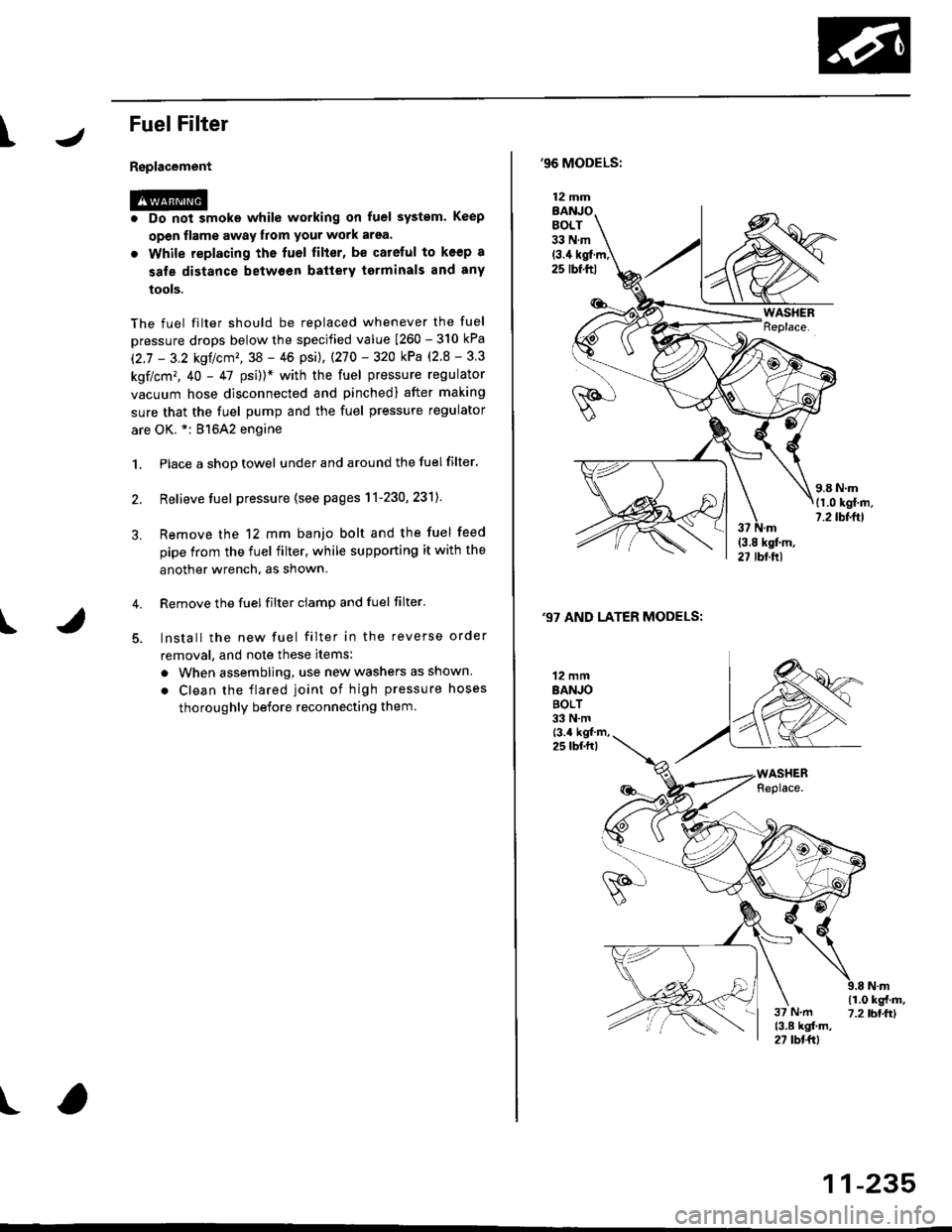
FuelFilter
Replacement
r@. Do not smoke whilc working on fuel system. Keep
open flame away from your work arsa.
. While replacing the tuel filter, be catelul to koep a
sale distance betwoen battery torminals and any
tools.
The fuel filter should be replaced whenever the fuel
pressure drops below the specified value [260 - 310 kPa
12.7 - 3.2 ksl/cm'�,38 - 46 psi), |270 - 320 kPa (2.8 - 3 3
kgf/cm,, 40 - 47 psi))* with the fuel pressure regulator
vacuum hose disconnected and pinchedl after making
sure that the fuel pump and the fuel pressure regulator
are OK. *: 81642 engine
1. Place a shop towel under and around the fuelfilter.
2. Relieve fuel pressure (see pages 11-230,231]-
Remove the 12 mm banjo bolt and the fuel feed
pipe from the fuel filter, while supporting it with the
another wrench, as shown.
Remove the fuel filter ciamp and fuel filter'
lnstall the new fuel filter in the reverse order
removal, and note these items:
a When assembling, use new washers as shown
. Clean the flared joint of high pressure hoses
thoroughly before reconnecting them.
I
,96 MODELS:
(3.4 kgl.m,25 rbf.ftl
,97 AND LATER MODELS:
12 mmBANJOBOLT33 N.m
12 mmBANJOBOLT33 N.mt3.4 kgf m,25 lbf.fr)
\i(o-r
)
11-235
Page 510 of 2189
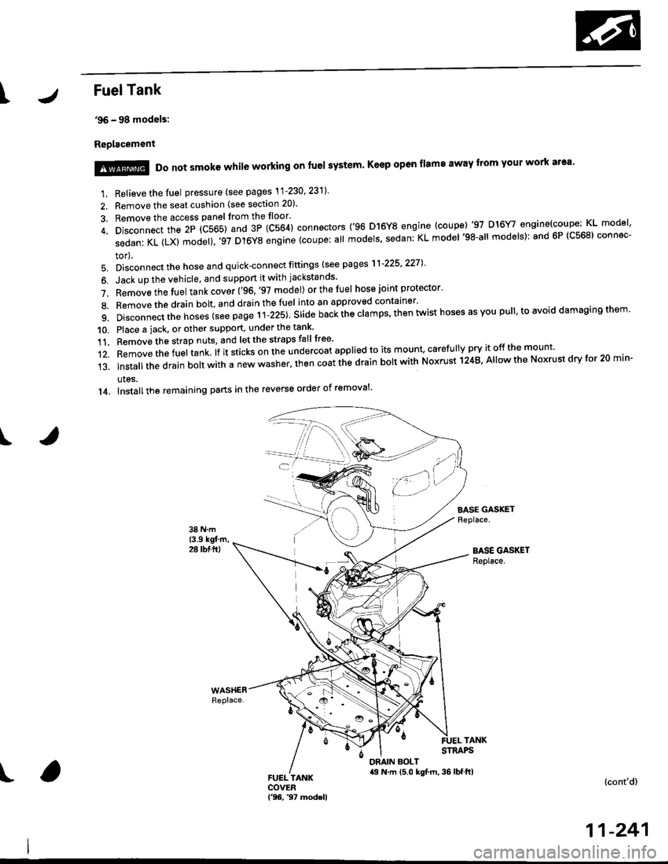
IFuelTank
'96 - 98 models:
Replacement
I
1. Relieve the fuel pressure (see pages \1-230' 23'll'
2. Remove the seat cushion (see section 20).
3. Remove the access panel from the floor'
4. Disconnect the 2P (C565) and 3P (C564) connectors ('96 D]6Y8 engine (coupe) '97 D16Y/ engine(coupe: KL model'
sedanKL(LX)model).'97D'l6YSengine(coupe:allmodels'sedan:KLmodel'98-allmodels):and6P(C568)connec-
tor),
5. Disconnect the hose and quick-connect fittings (see pag es'l'l-225' 2271
6. Jack up the vehicle, and support it with jackstands'
7. Removethefuel tank cover ('96,'97 model) orthefuel hose joint protector'
8. Bemovethedrain bolt,and drainthefuel into an approved container'
9. Disconnect the hoses {see page r i-izst. Sria" nu"i ihe clamps, then twist hoses as you pull, to avoid damaging them'
10. Place a jack. or other support, under the tank'
11. Remove the strap nuts, and let the straps fall free'
12. Removethefuel tank lf it sticks on the undercoat applied to its mount' caref u lly pry it off the mount'
13.|nsta||thedrainbo|twithanewwasher.thencoatthedrainbo|twithNoxrustl24B,A||owtheNoxrustdryfor20min-
ules.
14. Installthe remaining pans in the reverse order of removal'
SASE GASKETReplace.
BASE GASKETReplace.
!@@ Do not smoke while working on fuel system' Keep open flame away from your work ar'a'
TANKSTRAPS
DRAIN BOLT,19 N.m {5.0 kgt m, 36 lbf.ftl(cont'd)
11-241
Page 511 of 2189
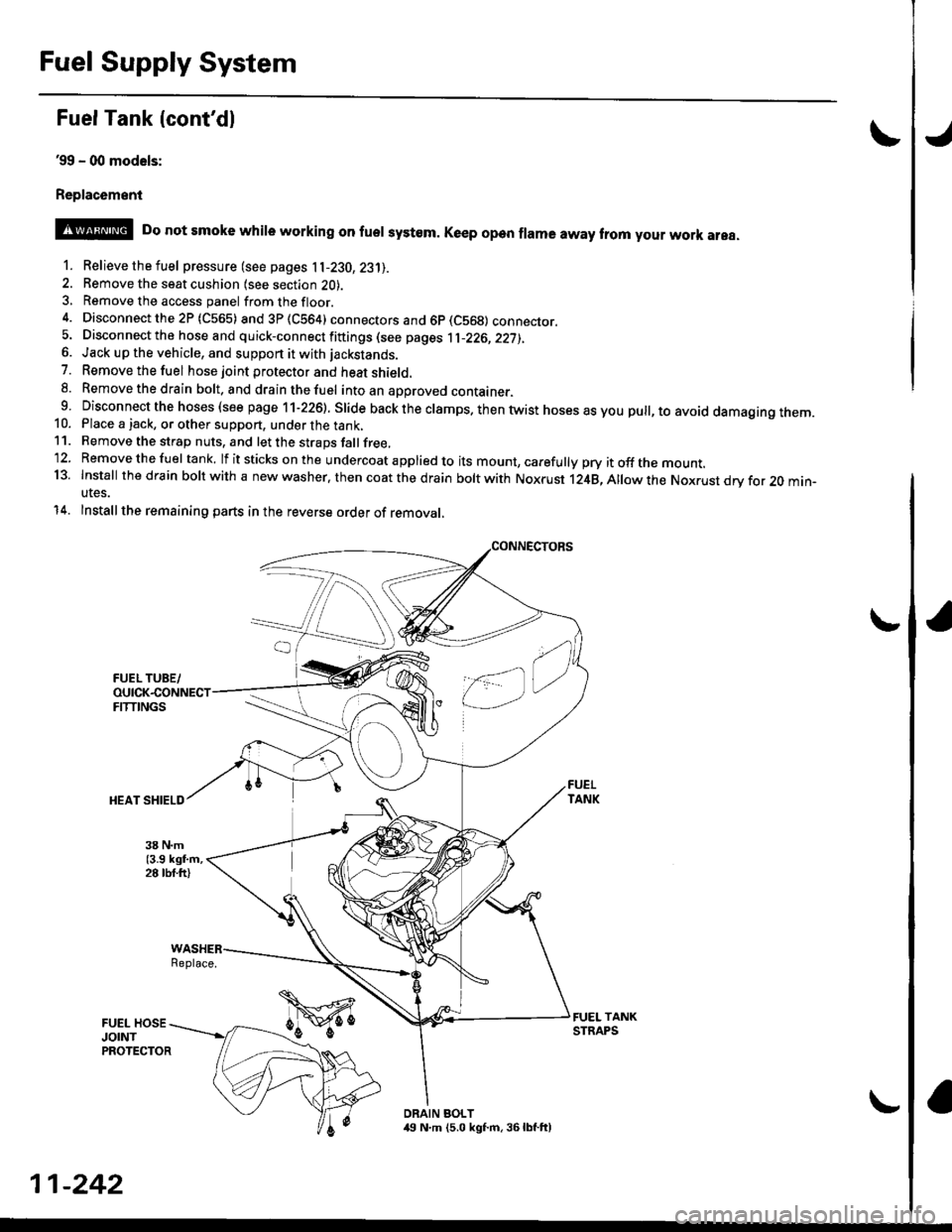
Fuel Supply System
Fuel Tank {cont'dl
39 - (xt models:
Replac6ment
o
@ Do not smoke whire working on fuer system. Ke€p open frama away trom your work area.
1. Relievethefuel pressure (see pages 11-230,23'll.
2. Remove the seat cushion lsee section 2O).3, Remove the access panel fromthefloor.
4. Disconnectthe2P (C565) and3P(CS64) connectors and 6p (C569) connecror.5. Disconnect the hose and quick-connect fiftings (see pages 1l-226,22j),6. Jack up the vehicle, and support it with jackstands.
7. Removethefuel hose joint protector and heat shield.8. Removethedrain bolt. and drainthefuel intoan aporoved container.9 Disconnect the hoses (see page 11-226). Slide back the clamps. then twist hoses as you pull, to avoid damagtng rnem.10. Place a jack, or other support, under the tank,11. Remove the strap nuts, and let the straps fallfree,'12. Removethefuel tank. lf itsticks onthe undercoat applied to its mount, carefully pry itoffthe mount.13. Install thedfain boltwith a new washer. then coat the d rain bolt with Noxrust 124B,Allowthe Nox.ust drv for 20 min-utes.
14. Installthe remaining parts in the reverse order of removal,
Replace.
DRAIN BOLT,19 N.m (5.0 kgf.m, 36lbf.ft)
11-242
Page 565 of 2189
Emission Gontrol System
Evaporative Emission (EVAP) Controls (cont'dl
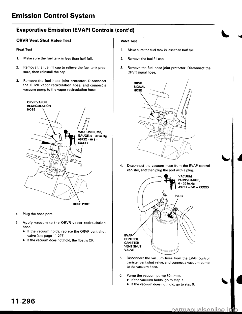
ORVR Vent Shut Valve Test
Float Test
1. Make sure the fuel tank is less than half full.
2. Remove the fuel fill cap to relieve the fuel tank pres-
sure, then reinstall the cap.
3. Remove the fuel hose joint protector. Disconnect
the ORVR vapor recirculation hose, and connect a
vacuum pump to the vapor recirculation hose.
ORVR VAPOERECIRCULATION
VACUUM PUMP/GAUGE,0 - 30 in.H9A973X - 041 -
xxxxx
Plug the hose port.
Apply vacuum to the ORVR vapor recirculation
nose.
. lf the vacuum holds, replace the ORVR vent shut
valve {see page 11-297).
. lf the vacuum does not hold, the float is OK.
4.
11-296
Vatve Tcst
1. Make sure the fueltank is lessthan halffull.
2. Remove the fuel fill cap.
3. Remove the fuel hose joint protector. Disconnect the
ORVR signal hose.
ORVRSIGNALHOSE
Disconnect the vacuum hose from the EVAP control
canister. and then plug the port with a plug.
VACUUMPUMP/GAUGE,0 - 30 in,HgA973X-041-XXXXX
CONTROLCANISTERVENT SHUTVALVE
Disconnect the vacuum hose from the EVAP control
canister vent shut valve, and connect a vacuum pump
to the vacuum hose,
Pump the vacuum pump 80 times.. lf the vacuum holds, go to step 7,. lf thevacuum does not hold, goto step9.
Page 629 of 2189
9. Remove the three upper transmission mounting
bolts and lower starter motor mounting bolt.
'10. Remove the engine splash shieid.
TRANSMISSIONMOUNTINGBOLTS12 x 1.25 mm
6,1 N.m (6.5 kgd m, 47 lbf'ft|
STARTERMOTORMOUNTINGBOLT10 x 1.25 mm
a,t N.m 14.5 kgl.m.
33 tbf.trl
CONNECTOE
11. Disconnect the heated oxygen sensor (HO2S) con-
nector, then remove exhaust pip€ A.
H02S
SELF.LOCKING NUTReplace.8 r 1.25 mm16 N.m (1.6 kgf.m, 12lbf'ft)
Replace.10 x 1,25 mm54 N.m {5.5 kgf.m,'lll lbf.ft)
12. Remove the cotter pins and loosen the castle nuts,
then separate the ball joints from the lower arm
(see section 18).
13. Remove the right damPer fork.
10 x 1.25 mma3 N.m lil.a kgf.m, 32 lbf'ft| ,
SELF.LOCKING NUTR6place.12 x 1.25 mm6a N.m (6.5 kgl.m,47 rbf ft)
RIGHTDAMPERFORK
CASTI.T NUT12 x 1,25 mma9 - 59 N.m (5.0 - 6.0 kgtm,36 - i(t lbf.ftl
(cont'd)
!-
ria -11: \/-/
't'''-a
SPLASH SHIELD
13-49
Page 632 of 2189
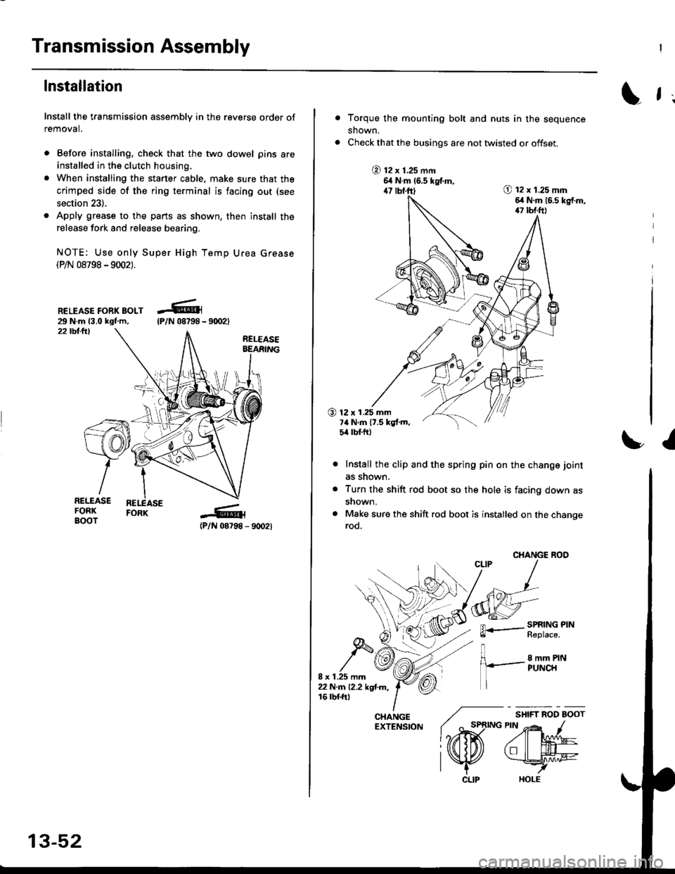
Transmission Assembly
lnstallation
Install the transmission assembly in the reverse order of
removal.
. Before installing, check that the two dowel pins are
installed in the clutch housing.
. When installing the starter cable. make sure that the
crimped side of the ring terminal is facing out (see
section 23).
. Apply grease to the parts as shown, then install the
release fork and release bearing.
NOTE; Use only Super High Temp Urea Grease(P/N 08798 -9002).
RELEASE FORK BOLT29 N.m 13.0 kgf.m,22 tbllrl
(P/N 08798 - 9rD2l
-R1
tP/N 08798 -
13-52
CLIP
L f ;
Torque the mounting bolt and nuts in the sequence
shown.
Check that the busings are not twisted or offset.
@ t2 x 1.25 mm6,t N.m 16.5 kgtm,47 lbf.ft)O t2 x 1.25 mm6,r N.m (6.s kg{.m,17 tbf.ft)
O 12 x 1.25 mm7ilNm17.5kgf.m,5it lbt ft)
I
Install the alip and the spring pin on the change joint
as snown.
Turn the shift rod boot so the hole is facing down as
snown.
Make sure the shift rod boot is installed on the changerod.
CHANGE ROO
FL.- SPRING PINll heptace,
8 mm PINPUNCH
/ "*,*
lo,iD(
CHANGE ./EXTENSfoN ( ^ st
l?rffi
l\K
Page 677 of 2189
Gearshift Mechanism
Overhaul
NOTE:
. Inspect rubber parts for wear and damage when disassembling;
. Install the spring pin and the clip on the change joint as shown'
. Turn the shift rod boot so the hole is facing down as shown'
. Make sure the shift rod boot is installed on the shift rod'
reDlace any worn or damaged Parts.
I x 1.25 mm22 N.m 12.2 kgf.m, 16 lbf.ft)
ffi-:t't:il1ii51i?"'*,
TU
/g3i'51!Exii
V ExrENsroN
EXTENSfON ilr'eol.T
EXTENSION ENDBUSHING
hV\
EXTENSIONWASI{ER B
MOUNT -_.--_-_---
@2'
--1'>=2 -:liT.i'ff"
.o,-.o*&--ffi{---*,
v/,,/ BALL SEAT
8 x 1.25 mm22 N.m 12.2 kgf'm, 16lblftl
,@
EXTENSION ROD
SHIFT ROD
SPRING
END
BOOT
N: g sHrFr LEvER
.*rr"r,o"-tf V-oiliiSi[a
MOUNTING I --::=t SHIFT I"EVERBRAcxEr / €9-l--enr xoloen
8 x 1.2s mm :-,rro""a,ii-ri- ri.z rsr.-, -.Q u
16 tbf.ft) ,,,.
,rar-aoa*,"o "u, / E ,",t.ruaa
Replace.6x1.0mm9.8 N.m ('1.0 kgt'm,7 tbr.ftt
8x22mmSPRING PINReplace.
IIt
@CLIP
9.a-"t't
PIN SHIFT ROD/
ZW
€lt#-,\
HOLE
13-97