Page 811 of 2189

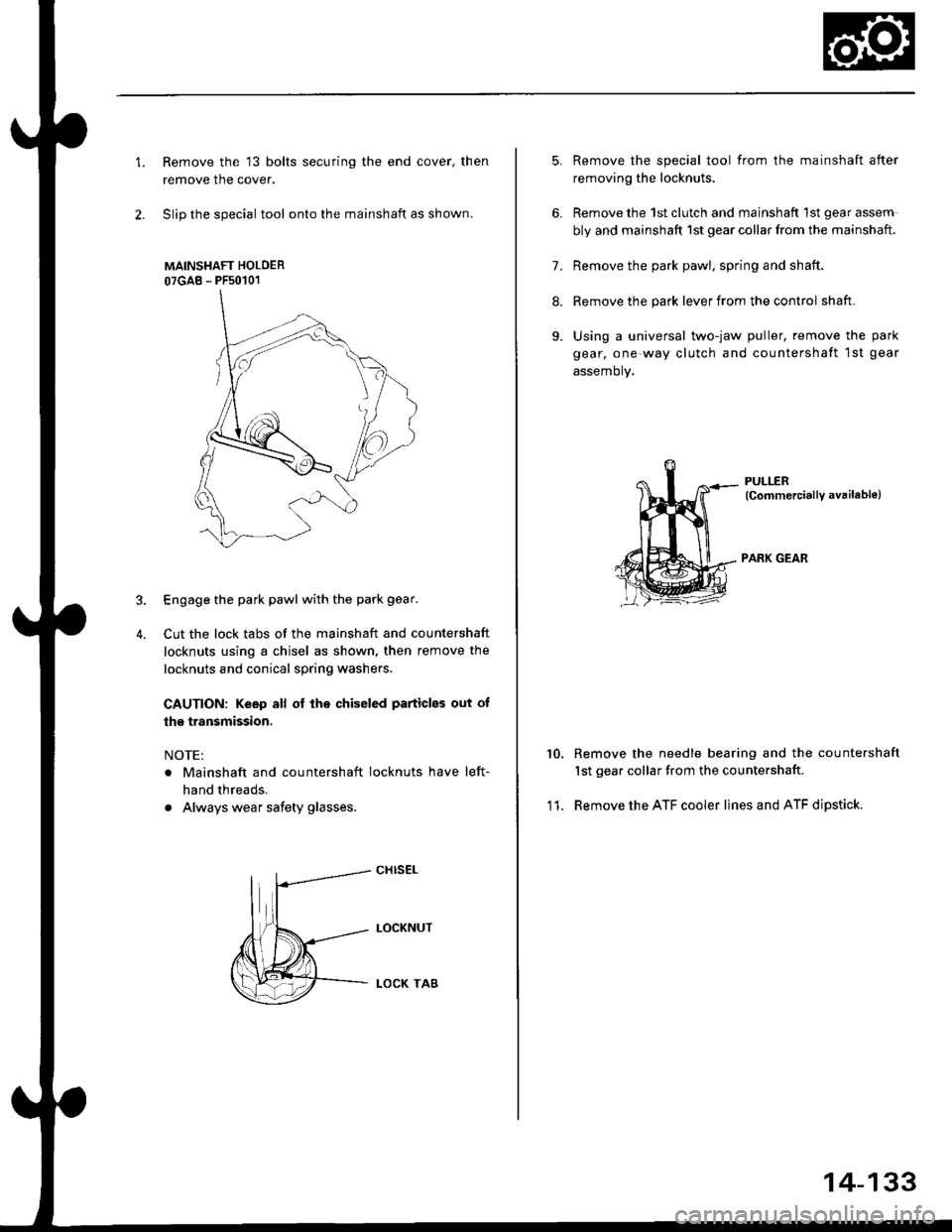
1.Remove the 13 bolts securing the end cover, then
remove the cover.
Slip the special tool onto the mainshaft as shown.
MAINSHAFT HOLOER
07GAB - PFs0101
Engage the park pawl with the park gear.
Cut the lock tabs of the mainshaft and countershaft
locknuts using a chisel as shown. then remove the
locknuts and conical spring washers
CAUTION: Keep all of lhe chiseled particles out of
the transmission.
NOTE:
. Mainshaft and countershaft locknuts have left-
hand threads.
. Always wear safety glasses.
4.
cHrs€L
LOCKNUT
LOCK TA8
5.
6.
11.
Remove the special tool from the mainshaft after
removing the locknuts.
Remove the 1st clutch and mainshaft 1st gear assem
bly and mainshaft 1st gear collar from the mainshaft.
7. Remove the park pawl. spring and shaft.
8. Remove the park lever from the control shaft.
9. Using a universal two-jaw puller, remove the park
gear, one way clutch and countershaft 1st gear
assemory.
PULLER(CommerciallY available)
PARK GEAR
10.Remove the needle bearing and the countershaft
1st gear collar from the countershaft
Remove the ATF cooler lines and ATF dipstick.
14-133
Page 812 of 2189
Transmission Housing
Removal
MAINSHAFT
TRANSMISSION HOUSINGMOUNTING BOLTS18 Bolts
TRANSMISSIONHANGERTRANSMISSION HOUSING
MAINSHAFTSUB.ASSEMBLY
SENSOR WASHERlD16Y7 engine)
MAINSHAFTSPEED SENSOR
TRANSMISSIONHOUSING GASKETDIFFEBENTIALASSEMBLY
TOROUE CONVERTERHOUSING
SUB.ASSEMBLY
L,
14-134
Page 826 of 2189

Mainshaft
Disassembly/lnspestion/Reassembly
NOTE:
. Lubricate all parts with ATF during reassembly..Inspectthethrustneedlebearingsandtheneedlebearingsforgallingandroughmovement,
. Before installing the O-rings, wrap the shaft splines with tape to prevent damaging the O_rings.. Locknut has left-hand threads.
LOCKNUT {FLANGE NUTI21 x 1.25 mm78 N.m (8.0 kgl.m,58 lbt.fttReplace.Left-hand threadsSNAP RINGCONICAL SPRING WASHERReolace.
lST CLUTCHASSEMBLYTHRUST WASHER
THRUST NEEOI.EBEARING
4TH GEAN
O-RINGSReplace.
THRUST WASHER
THRUST NEEDLEBEARING
MAINSHAFTCheck splines for excessivewear and oamage.Check bearing surtace for scoring,scratches and excessive wear.
BEARINGBEARINGS
THRUST NEEDLEBEABING
4TH GEAR COLLAR
2ND/4TH CLUTCHASSEMBLY
THRUST NEEDLEEEARING
2NO GEAB
NEEDLE BEABING
THRUST NEEDLEBEARING
1ST GEAR
1ST GEARCOLLAR
TRANSMISSIONHOUSING BEARING
O-RINGSReplace.
THRUST WASHER, 36.5 x 55 mmSelective part.
SEALING RINGS,35 mm
Install the sealing ringmating faces as shown,
RING,29 mm
NEEDLE BEARING
SET RING
14-148
Page 829 of 2189
Countershaft
Disassembly/lnspection/Reassembly
NOTE:
. Lubricate all parts with ATF before reassembly'
. tnrp"",,n",t -"t needle bearings and the needle bearings for galling and rough movement'
. Before installing the O-rings. wrap the shaft splines with tape to prevent damaging the O-rings
. Locknut has left-hand threads
LOCKNUT (FLANGE NUT}
23 x 1.25 mm103 N.m
{10.5 kgf'm, 75.9 lbf'tt)
Replace.Left'handlhreads
CONTCAL SPRING
WASHERReplace.
GEAR
CLUTCH
1ST GEAR
BEARING
lST GEAR COLLAR
TRANSMISSIONHOUSING BEARING
REVERSE GEAR
NEEDLEBEARING
SELECTOR
SELECTOR
4TH GEAR
NEEDLE BEARING
DISTANCE COLLAS,
28 mmSelective pa .
COUNYERSHAFTCheck splines lor excesslve
wear and damage
2'{D GEAR
THRUST NEEDLEBEARING
3RD GEAB
NEEDLE BEARING
3RD GEAR COLLAR
THRUST NEEDLE EEARING
SPLINEO WASHER
3RD CLUTCH ASSEMBLY
Check bearing surface for scoring'
scratches and excessive wear'
Replace.
1+151
Page 832 of 2189

Gountershaft
Inspection (cont'dl
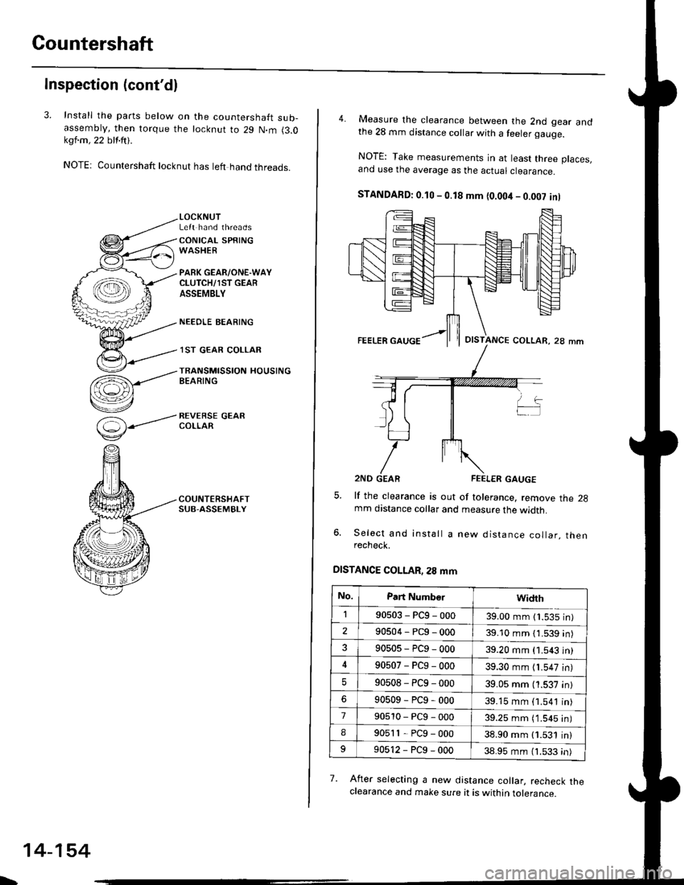
3. Install the parts below on the countershaft sub-assembty, then torque the locknut to 29 N.m (3.0kql.m , 22 blf.ftt .
NOTE: Countershaft locknut has left hand threads.
(=)-----'
v
LOCKNUTLeft hand threads
CONICAL SPRINGWASHER
PARK GEAR/ONE.WAYCLUTCH/1ST GEARASSEMBLY
NEEOLE BEARING
.I ST GEAR COLLAR
TRANSMISSION HOUSINGBEARING
REVERSE GEARCOLLAR
\
14-154
4. Measure the clearance between the 2nd gear andthe 28 mm distance collar with a feeler gauge.
NOTE: Take measurements in at least three places.and use the average as the actuar ctearance.
STANDAFD: 0.10 - 0.18 mm {0.004 - 0.002 inl
lf the clearance is out of tolerance. remove the 2gmm distance collar and measure the width.
Select and install a new distance collar, thenrecheck.
DISTANCE COLLAR, 28 mm
7. Afret selecting a new distance collar, recheck theclearance and make sure it is within tolerance.
OISTANCE COLLAR, 28 mm
No.Part Numb€rwidrh
190503-PCg-00039.00 mm (1.535 in)
290504-PCg-00039.10 mm { 1.539 in)
90505-PCg-00039.20 mm (1.543 in)
90507-PCg-00039.30 mm {1.547 in)
90508-PC9-00039.05 mm (1.537 in)
90509-PCg-00039.15 mm (1.541 in)
790510-PCg-00039.25 mm ( 1.545 in)
I90511-PCg-00038.90 mm (1.531 in)
90512-PCg-00038.95 mm (1.533 in)
Page 834 of 2189
Clutch
lllustrated Index (A4RA, B4RA Transmission)
3RD CLUTCH
O-RINGSBeplace. CLUTCH ptSTON
lST CLUTCH
CLUTCHDRUM
CLUTCH ENDPLATE
SPRING RETAINER
RETUNN SPRING
CLUTCH DRUM
SNAP RING
CLUTCH END
CLUTCH PLATESStandard thickness:1.6 mm (0.063 in)
SNAP RING
CHECK VALV€
\
14-156
Page 836 of 2189
Clutch
lllustrated Index (M4RA Transmission)
3RD CLUTCHCLUTCHDRUM
CLUTCH PISTON
DISC SPRING
CLUTCII END
rST CLUTCH
CLUTCH E D
SI{AP RIiIG
CLUTCH PLATESStandard thickness:1.6 mm (0.063 in)
CHECK VALVE
L
14-158
Page 843 of 2189

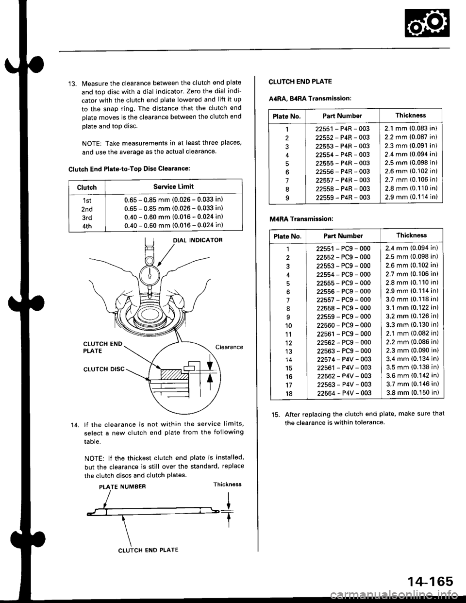
13. Measure the clearance between the clutch end plate
and top disc with a dial indicator' Zero the dial indi-
cator with the clutch end plate lowered and lift it up
to the snap ring. The distance that the clutch end
plate moves is the clearance between the clutch end
plate and top disc.
NOTE| Take measurements in at least three places,
and use the average as the actual clearance.
Clutch End Plste-to-Top Disc Clearance:
OIAL INDICATOR
CLUTCH ENDPLATEClearance
14.
CLUTCH DISC
lf the clearance is not within the service limits,
select a new clutch end plate from the following
table.
NOTE: lf the thickest clutch end plate is installed,
but the clearance is still over the standard, replace
the clutch discs and clutch plates.
PLATE NUMBERThickn6ss
ClutchSerYice Limit
1st
2nd
3rd
4th
0.65 - 0.85 mm (0.026 - 0.033 in)
0.65 - 0.85 mm (0.026 - 0.033 in)
0.40 - 0.60 mm (0.016 - 0.024 in)
0.40 - 0.60 mm (0.016 - 0.024 in)
CLUTCH ENO PLATE
14-165
Plate No.Part NumberThickness
,l
2
J
4
5
6
1
8q
22551 - P4R - 003
22552-P4R-003
22553-P4R-003
22554-P4R-003
22555-P4R-003
22556-P4R-003
22557 -P4B-OO3
22558-P4R-003
22559-P4R-003
2.1 mm (0.083 in)
2.2 mm (0.087 in)
2.3 mm (0.091 in)
2.4 mm (0.094 in)
2.5 mm (0.098 in)
2.6 mm (0.102 in)
2.7 mm {0.106 in)
2.8 mm {0.110 in)
2,9 mm (0.1 '14 in)
CLUTCH END PLATE
A4RA, g4RA Transmission:
M,IRA Transmi$ion:
15. After replacing the clutch end plate. make sure that
the clearance is within tolerance.
Plate No.Part NumberThickness
1
3
'l
.'q
10
11't2
13
14
15'16
17
18
22551 - PCg - 000
22552-PCg-000
22553-PCg-000
22554-PCg-000
22555-PCg-000
22555-PCg-000
22557-PCg-000
22558-PCg-000
22559-PCg-000
22560-PCg-000
22561 - PCg - 000
22562-PCg-000
22563-PCg-000
22574 - P4V - 003
22561 - P4V - 003
22562- P4V - 003
22563-P4V-003
22564-P4V-003
2.4 mm (0.094 in)
2.5 mm (0.098 in)
2.6 mm {0.102 in)
2.7 mm (0.106 in)
2.8 mm (0.110 in)
2.9 mm (0.114 in)
3.0 mm {0.118 in)
3.1 mm (0.122 in)
3.2 mm (0.126 in)
3.3 mm (0.130 in)
2.1 mm (0.082 in)
2.2 mm {0.086 in)
2.3 mm (0.090 in)
3.4 mm (0.134 in)
3.5 mm (0.138 in)
3.6 mm (0.142 in)
3.7 mm (0.146 in)
3.8 mm (0.150 in)