Page 1233 of 2189
l}
GLASSReplacement,page 20 6Adiustment,page 20-20GLASS RUNCHANNEL
CENTER LOWERCHANNEL
eCYLINDERPBOTECTORREGULATORReplacement,page 20-6LOCK RODPROTECTOR
STRIKER 'Adjustment, llpage 20-23
tt t[
#-l|r&
/h)
/Y
LATCHReplacement,20-6
LOCKCYLINOERRETAINERCLIP
^o
?'2'
ourER HANoLE
ecuLaron
HANOLE
POWER DOORLOCK SwlTCH(driver's only)
Replacement, page 20-5
INNEN HANDLE ROD
LATCHPROIECTOR
-) /
s/
*Nqd'
/ -"-/
tt\
. '\
It
INNERHANDLE
20-3
Page 1234 of 2189
Doors
Door Panel Replacement
NOTE; Take care not to scratch the door panel and otherpans.
1. Remove:
. Inner handle (see page 20-3)
. Mirror mount cover panel (see page 20-24)
2. lf applicable, remove the regulator handle by pulling
HANOLE
3. Remove the door grip cover and speaker cover, thenremove the screws.
>: Screw locations, 5POWER WTNOOWswtTct{
the clip out with a wire hook.
20-4
4. Release the clips that hold the door panel. Remove
the door panel by pulling it upward.
NOTE: Remove the door panel with as little bending
as possible to avoid creasing or breaking it.
95 mm {3.74 in.)
.L12 mm(0.47 in.) fTRIM PADREMOVER(Commercially
availablelSnap-on#A'177, o.equivalenllmm(0.04 in.l
r_
rr-l
45 mm(1.77 in.l
>i Clip loc.tions, 5
lu-i
J$- I
:fe i
cL,P / IREMovERil I
_ _t/
Dasconnect the;peaker connector,
5. lnstallation is the reverse of the removal procedure.
Page 1238 of 2189
Doors
Rear Door Index
,[D:
OUTERWEATHERSTRIP
INNERWEATHERSTRIP
DOORAdjustment,page 20-23
INNER MOLDING
fu4 ffir",
M
R*
/-HINGEPOWER WTNDOW \a-sw[cH
\\€\
\;\
€ -*r'
*e€
(=__: \:-? \
/\
/\/ DooR
/ GRIP
DOOnGRIPCOVER
o(x)RPROTECTOR
t\
\
PLASTICCOVER
20-8
Page 1239 of 2189
\L
lJ\
\flREAR CHANNEL N\
\,\
\
\i\Ill
ld 1l
6P lll
REo" c"AN"..: | 1lcoLLAR J I
)€)\IJ
6/
\3-
REGULATORHANOLE
:& fr\
r lll'All criss lLl
l'A sroeeen lll
W-*d
t a)" u\
*)u*ro* \
Repracement, pase 20 ,tt
l5[1tfCHANNEL
OUTER HANDLEReplacement, Page 20-11
STRIKERAdjustment,page 20'23
I
I
%grc
POWER WINDOWMOTOR
LOCK RODPROTECTOR
LATCHPROTECTORReplacement,page 20-12
POWER OOORLOCK ACTUATOE
t
20-9
Page 1243 of 2189

t}
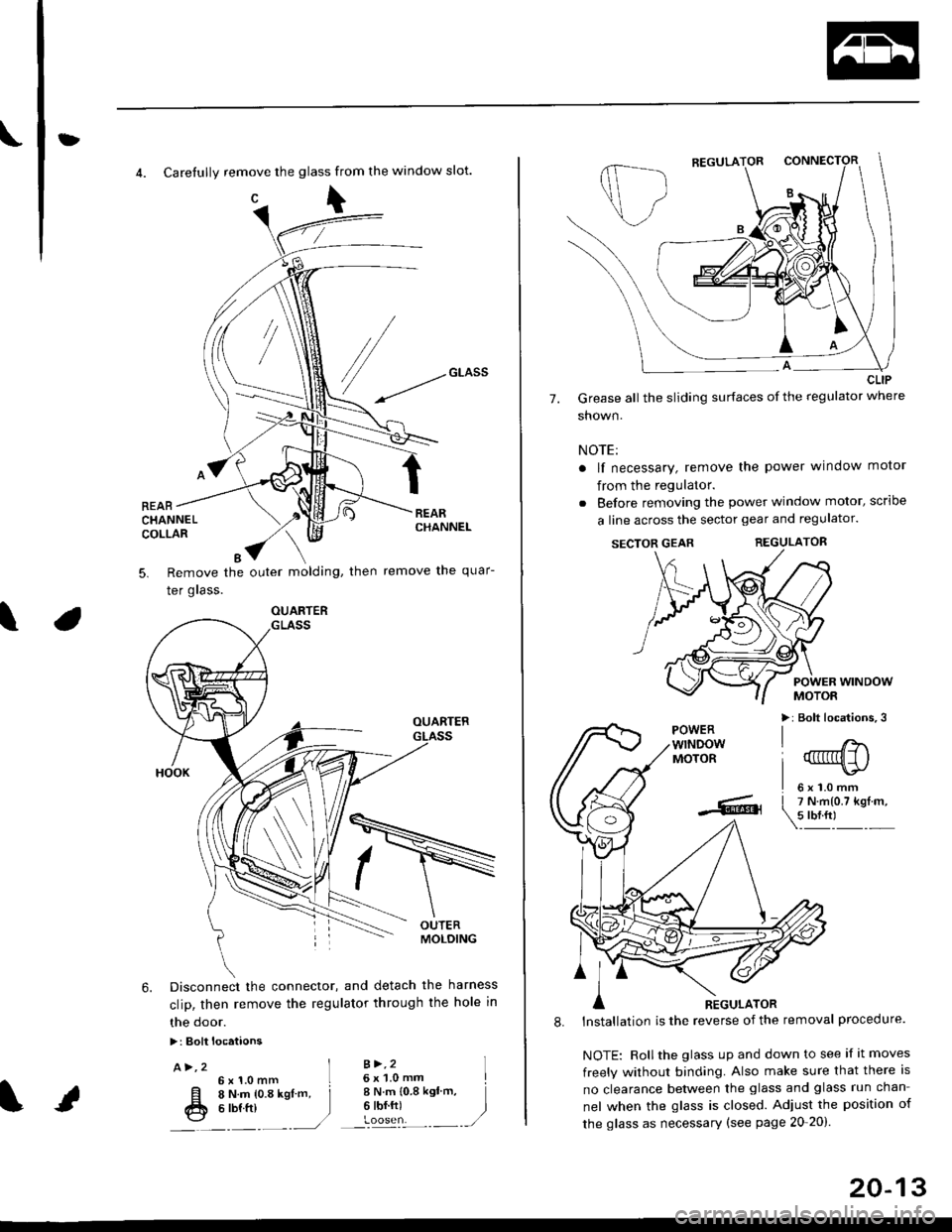
4. Carefully remove the glass from the window slot.
c\
REARCHANNELCOLLAR
Remove the outer molding, then
Ier grass.
remove the quar-5.
\
6. Disconnect the connector, and detach the harness
clip, then remove the regulator through the hole in
the door.
>: Bolt locataons
A>,2 ]6x1.0mm L
[l o t't.- to.a rsl -. j
fr e ttt ttt )---�.---.-,/
B >,26 x 'l.0 mmI N.m {0.8 ksl'm,6 tbf.ft)
I
)
OUARTER
20-13
7.
CLIP
Grease all the sliding surfaces of the regulator where
shown.
NOTE:
a lf necessary, remove the power window motor
from the regulator.
. Before removing the power window motor, scrloe
a line across the sector gear and regulator.
SECTOR GEARREGULATOR
POWER WINDOWMOTOR
>: Bolt locations,3POWERwTNDOWMOTOR
l'
-... er
A nicuuron
8. lnstallation is the reverse of the removal procedure.
NOTE: Rollthe glass up and down to see if it moves
freely without binding. Also make sure that there is
no clearance between the glass and glass run chan-
nel when the glass is closed. Adjust the position of
the glass as necessary (see page 20-20).
Page 1244 of 2189
Doors
Door Index
2DI3D:
OU?ERWEATHERSIRIP
GLASS GUIDECLIP
I sAsH
€*/
.u\
\Y\I
et'
SPEAKER COVER
INNER HANDLE
ii MTRROR MOUNT<]<-- COVER PANEL
-it v
$=-!xtruce
re
(sqjR5f"'
@." \s-l
h-P
-Qa,
(l+,
@
TRIM(with power door locks)
eowen ooon
rocK swrrcH
\b
INNEF HANOLETRIM{without power
dD door locks)
DOORAdjustment,page 20-23
BRACKET
dl
h
W/
ARMRESTPOCKET
;ril;"i-"- 9
JE
powen____-.-@
wtNDow .*\L'l
swrrcH
t
-p
Q*-BsfL-,"ARMRESTPOCKETlwith power
PLASTICCOVER
,",
S
dnJ.*-{
r-1*{
,P
SPEAKER
20-14
Page 1245 of 2189
?
GLASSReplacement,page 20-19Adjustment,page 20-20
GLASS RUNCHANNEL
3ill,'^lri"*'"tt--.-.qq
\,
\I\\II REGULATOR
\ neptacement, page zo rs
\'l 6
trq\ v.
CYLINDERPROTECTOR
tr
POWERMOTOR
LATCHReplacement,page 20-18
STRIKERAdjustment,page 20-23
\
fitn
\a\.vqE
LOCKCYLINDER
RETAINEBCLIP
BOD PROTECTOR
INNER HANDLE ROD
LATCHPROTECTOR
20-15
Page 1246 of 2189
Doors
Door Panel Replacement
NOTE: Take care not to scratch the door panel andother pa rts.
'1. Remove:
. Inner handle trim (see page 20-14). Mirror mount cover panel (see page 20-24)
2. lf applicable, remove the regulator handle bypulling the clip out with a wire hook.
REGULATOR HANDLE
WIRE HOOK
Remove the armrest pocket, then disconnect thepower window switch connector.
ARMRESTPOCKET
4. Remove the speaker cover, then remove lhe screws.
3.
I
>: Screw locations, 3
| 6b:a,'
L"_
COVER
20-16
TRIM PADREMOVER(Commercially
available)Snap-on#A'177, orequivalent1mm{0.04 in.)
5. Release the clips that hold the door panel. Removethe door panel by pulling it upward. Disconnect thespeaker connector.
NOTE: Remove the door panel with as little bendingas possible to avoid creasing or breaking it.
.L12 fim(0.47 in.) T-
>: Clip locations,
l^
J[
=l$
ll,\*
atr-
,,)
REMoVER tl-)
11.77 in.l
O) CONNECTOR
6. lnstallation is the reverse of the removat oroceoure.
DOOR PANEL