Page 1178 of 2189
Rear Brake Pads
Inspection and Replacement
Never use an air hose or dry brush to clean brakeassemblies.
Use an OsHA-apptoved vacuum cl€aner to avoidbreathing brake dust,
Block the front wheels, loosen the rear wneet nutsslightly, support the rear of the vehicle on safetystands, then remove the rear wheels.
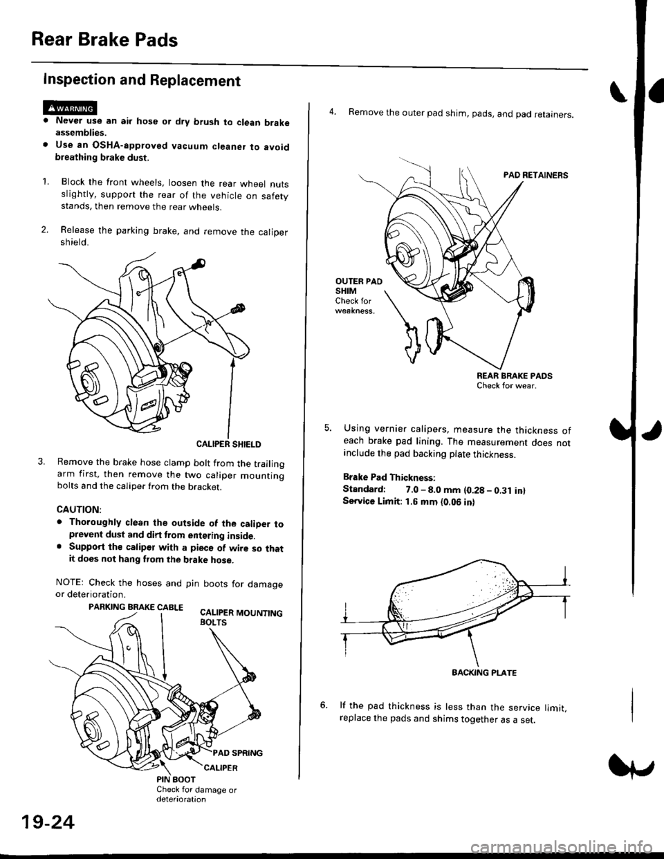
Release the parking brake, and remove the calioersh ield.
CALIPER SHIELD
Remove the brake hose clamp bolt from the trailingarm first, then remove the two caliper mountingbolts and the caliper from the bracket.
CAUTION:
. Thoroughly clean the outside of the caliDer toprevent dust and dirt trom entering inside.. Support the calipor with a pieco of wire so thatit does not hang fuom the brake hose.
NOTEr Check the hoses and pin boots for damageor deterioration.
PARKING BRAKE CABLE ^.. ._-_ ---.
'L
19-24
4. Remove the outer pad shim, pads, and pad retainers.
PAO RETAINERS
OUTER PAOSHIMCheck for
REAR BRAKE PADSCheck for wear.
Using vernier calipers, measure the thickness ofeach brake pad lining. The measurement does notanclude the pad backing plate thickness.
Brake Pad Thickness:
Standard: 7.0 - 8.0 mm {0.28 - 0.31 in}Service Limit: 1.5 mm {0.06 in}
lf the pad thickness is less than the service limit,replace the pads and shims together as a set.
BACKING PI-ATE
Page 1179 of 2189
I
7.
11.
Clean the caliper thoroughly; remove any rust, and
check for grooves and cracks.
Check the brake disc for damage and cracks.
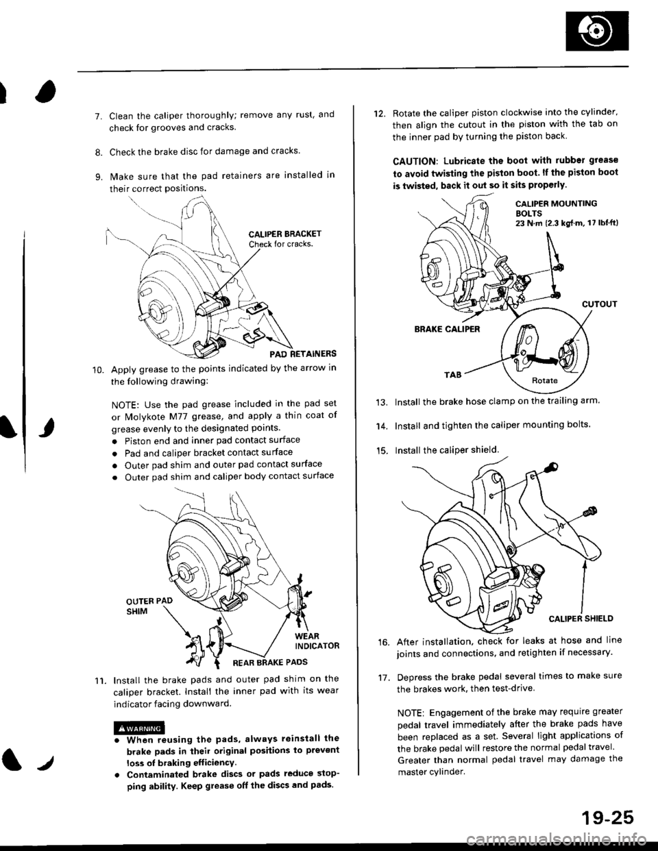
lvlake sure that the pad retainers are installed in
their correct positions.
PAD RETAINERS
Apply grease to the points indicated by the arrow in
the following drawing:
NOTE: Use the pad grease included in the pad set
or lMolykote M77 grease, and apply a thin coat of
grease evenly to the designated points.
. Piston end and inner pad contact surface
. Pad and caliper bracket contact surface
. Outer pad shim and outer pad contact surface
. Outer pad shim and caliper body contact surface
lnstall the brake pads and outer pad shim on the
caliper bracket. Install the inner pad with its wear
indicator facing downward.
@iwhen reusing the pads, always reinstall the
brake pads in iheil original posiiions lo prevont
loss ol braking efficiency
. Contaminaled brake discs or pads reduce stop-
ping ability. Keep grease off the discs and pads.
t./
19-25
12. Rotate the caliper piston clockwise into the cylinder'
then align the cutout in the piston with the tab on
the inner pad by turning the piston back
CAUTION: Lubricate ths boot with rubber grease
to avoid twisting the piston boot. lf the piston boot
is twisted, back it out so it sits properly.
CALIP€R MOUNTINGBOLTS23 N,m {2.3 kg{.m, 17 lbt'ft)
13.
14.
15.
CUTOUT
BRAKE CALIPER
Install the brake hose clamp on the trailing arm.
Install and tighten the caliper mounting bolts.
Install the caliper shield.
After installation. check for leaks at hose and line
joints and connections, and retighten if necessary.
Depress the brake pedal several times to make sure
the brakes work, then test-drive
NOTE: Engagement of the brake may requrre greater
pedal travel immediately after the brake pads have
been replaced as a set. Several light applications of
the brake pedal will restore the normal pedal travel.
Greater than normal pedal travel may damage the
master cylinder.
16.
17.
Page 1180 of 2189
Rear Brake Disc
Disc Runout Inspection
1.Loosen the front wheel nuts slightly, then raise thevehicle, and suppon it on safety stands. Removethe front wheels.
Remove the brake pads (see page 19-24).
Inspect the disc surface for damage and cracks.Clean the disc thoaoughly, and remove a
rust.
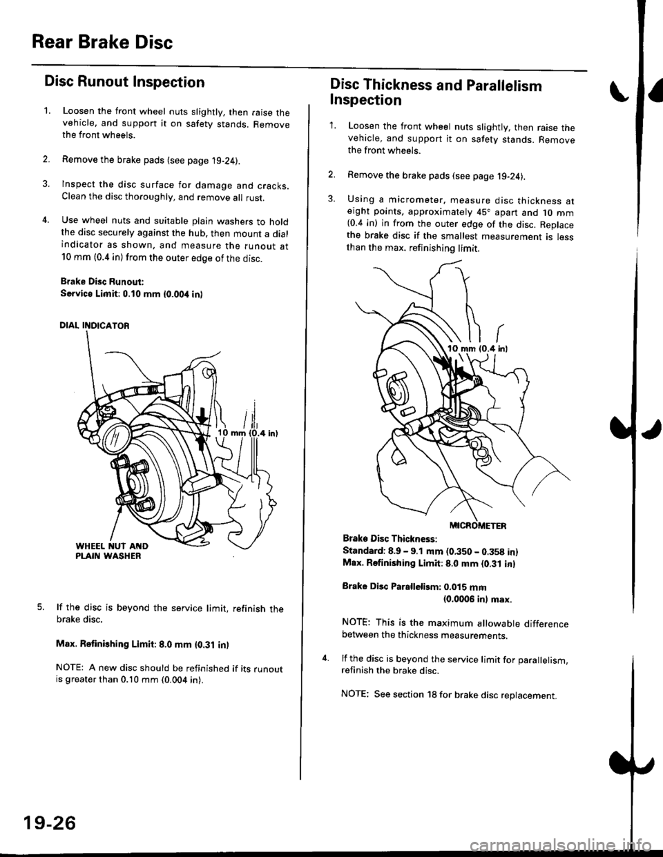
Use wheel nuts and suitable plain washers to holdthe disc securely against the hub. then mount a dialindicator as shown. and measure the runout at10 mm (0.4 in) from the outer edge of the disc.
Brake Disc Runout:
Service Limit:0.10 mm {0.00,t in)
5. lf the disc is beyond the service limit, refinish thebrake disc,
Max. Retinishing Limit: 8.0 mm {0.31 in)
NOTE: A new disc should be refinished if its runoutis greater than 0.10 mm (0.004 in).
19-26
Disc Thickness and Parallelism
Inspection
1. Loosen the front wheel nuts slightly, then raise thevehicle, and support it on safety stands. Removethe front wh6els.
2. Remove the brake pads (see page j9-24).
3. Using a micrometer. measure disc thickness aterght points, approximately 45" apart and 1o mm{0.4 in) in from the outer edge of the disc. Replacethe brake disc if the smallest measurement is lessthan the max. refinishing limit.
Brake Disc Thickness:
Standard: 8.9 - 9.1 mm (0.350 - 0.358 in)Max. Rsfinishing Limit: 8.0 mm {0.31 in}
Brake Disc Parallelirm: 0.015 mm(0.0006 inl msx.
NOTE; This is the maximum allowable differencebetween the thickness measurements.
4. lf the disc is beyond the service limit for Darallelism.refinish the brake disc.
NOTE; See section 18 for brake disc replacement.
Page 1181 of 2189
Rear Brake Caliper
Disassembly
@f l',lever use an air hose or dry brush to clean
assemblies.
. Use an OsHA-approved vacuum cleaner to
brake
avoid
breathing brake dust.
. Contaminated brake discs or pads reduce stopping
ability.
CAUTION:
. Do not spill brake tluid on the cal; h may damage the
paint; if brake fluid does contact the paint, wash ii
ofl immediatelY with water.
. To prevent spills, cover the hose ioints whh rags or
shop tow€ls.
. Clean all parts in brake fluid and air dry; blow out all
passagss with complessed air.
1. Remove the caliper shield (see page 19-24).
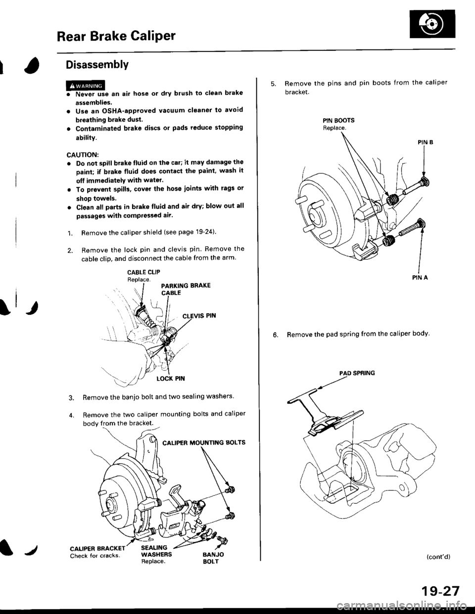
2. Remove the lock pin and clevis pin. Remove the
cable clip, and disconnect the cable from the arm
CABLE CLIP
Remove the banjo bolt and two sealing washers
Remove the two caliper mounting bolts and caliper
body from the bracket.
CALIPER MOUNTNG AOLTS
CALIPER BRACKETCheck for cracksSEALINGWASHERSReplace.BANJOBOLT
5, Remove the pins and pin boots from the caliper
bracket.
6. Remove the pad spring from the caliper body
PIN A
(cont'd)
19-27
Page 1182 of 2189
Rear Brake Galiper
Disassembly (cont'd)
7. Remove the piston by rotating the piston counter-clockwise with the tool, and remove the piston
boot.
CAUTION: Avoid damaging the piston.
PISTON BOOTReplace.
Remove the piston seal.
CAUTION: Take care not to damage the cylinderbore.
CALIPER BODYCheck for scoring on
9. Install the special tool between the caliper bodv andspnng cover.
CAUTION: Be caretul not to damags the inside ofthe caliper cylinder during caliper disassembty.
BRAKE SPRINGCOMPRESSOR07HAE - SG00100
11.
LOCKNUTS
Position the locknuts as shown. then turn the shaftuntil the plate just contacts the caliper body.
NOTE: Do not compress the spring under thespring cover.
Turn the shaft clockwise 1/4 -'ll2 tu.n to comoressadjusting spring B in the caliper body.
CAUTION: To preyant damage to the inner compo-nonts. do not turn the shaft mor€ than 1/2 turn.
SHAFT
LOCKNUTS
PISTON SEALReplace.
ADJUSTII{GSPRING 8
19-28
Page 1184 of 2189
Rear Brake Galiper
Disassembly (cont'dl
18. Remove the return spring.
PARKING LEVER/CAM ASSEMBLYCheck lor damage.
Remove the parking lever and cam as an assemblvfrom the caliper body.
CAUTION: Do not loosen the parking nut with thecam inslalled in the caliper body, lf the leyer andshaft must be separated, hold the lever in a vise,and loosen the parking nut,
Remove the cam boot.
RETURNSPRING
19.
19-30
Page 1185 of 2189
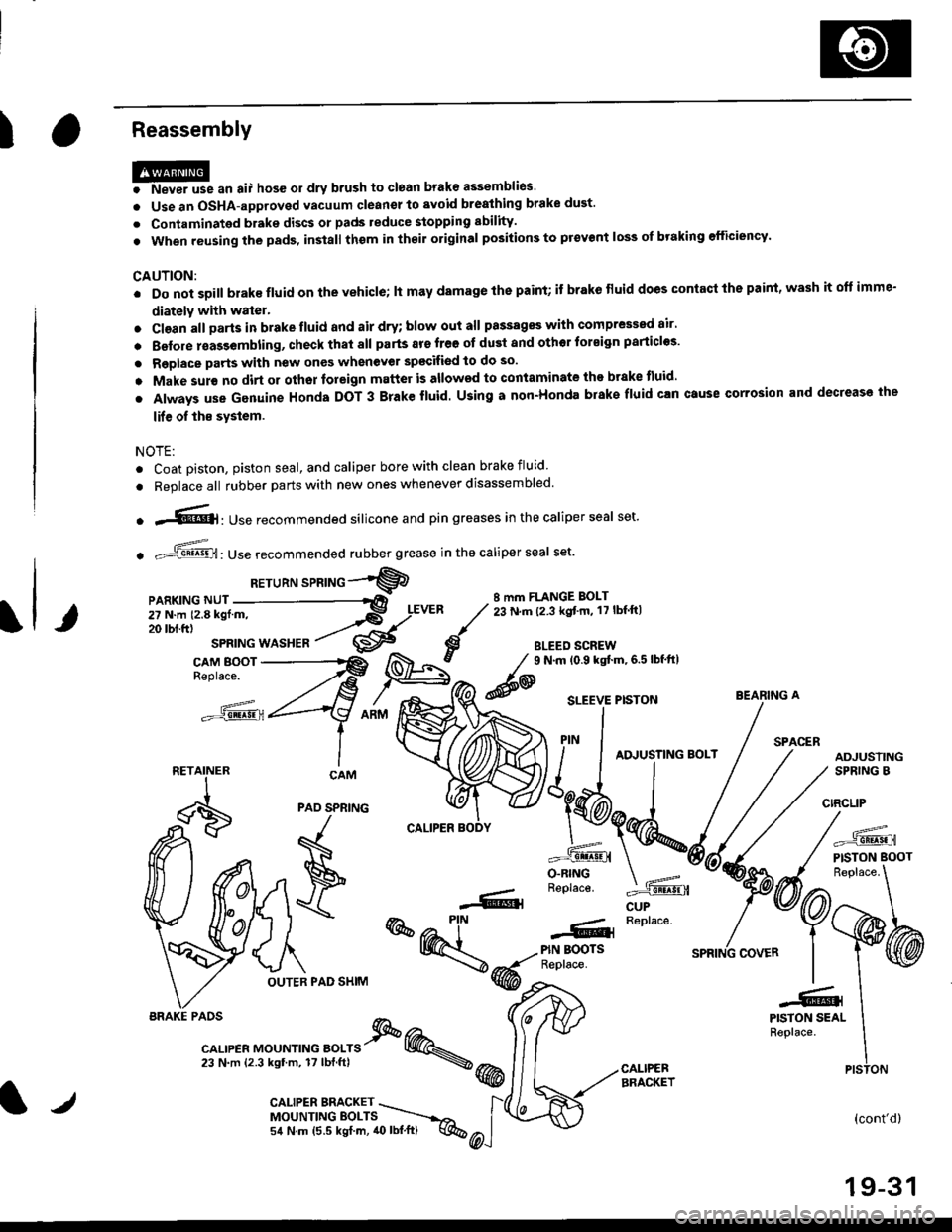
IReassembly
HP* "n ",, hos6 or drv brush to ctoan brake assemblies.
o Use an OSHA-approved vacuum cleanel to avoid brealhing brake dust'
. Contaminated brake discs or pads reduce stopping sbility.
. When reusing the pads, in3tall thom in thoil original positions to prevent loss of braking efficiency'
CAUTION:
. Do not soill brake fluid on the vehicle; lt may damage lhe paint; if brake fluid does contacl the paint' wash it oft imme-
diately with water.
. Cl€an all Darts in brake fluid and air dry; blow out all passagss with comPressed air'
. Belore rsas3embling, check that all parts ars free ot du3t and othor tor€ign particles'
. Replace parts with new ones whenever spscifiod to do so.
o Make sur€ no dirt or othor foreign matter is allowed to contaminate the brake tluid'
. Always use Genuine Honda DOT 3 Brake fluid. Using a non-Honda brake fluid can Gtuse corrosion and decrease the
lif€ of ths system.
NOTE:
. Coat piston, piston seal, and caliper bore with clean brake fluid
. Replace all rubber parts with new ones whenever disassembled.
o .-'{@]: Use recommended silicone and pin greases in the caliper seal set.
. -ffi,Use recommended rubber grease in the caliper seal set.
RETuRN sPRTNG -"'9
8 mm FLANGE BOLT23 N.m (2.3 kgt'm, 17 lbf ftl
BLEED SCREW
@
9 N.m (0.9 kgtm,6.5lbf'ft|
CUP
=^.
PISTON BOOT
(cont'd)
19-31
BEARING A
PAO SPNING
F
\
OUTER PAD SHIM
r--- Replace..ffiPIN BOOTSReplace.
-61
@@-t-.
"l-r,r., "or"'*o " orr" I @.,23 N.m {2.3 kgtm, 17lbf.ftl \@
PISTON SEALReplace.
CALIPEBBRACKET
iiilji:ll;;
__X.,,..".^
BRAKE PAOS
PISTON
l/CALIPER BMCKET \MOUNTINGEOLTS ----.-,o,
54 N.m (5.5 kgf.m, 40lbl.ft) q%
Page 1186 of 2189
Rear Brake Caliper
Reassembly (cont'dl
L
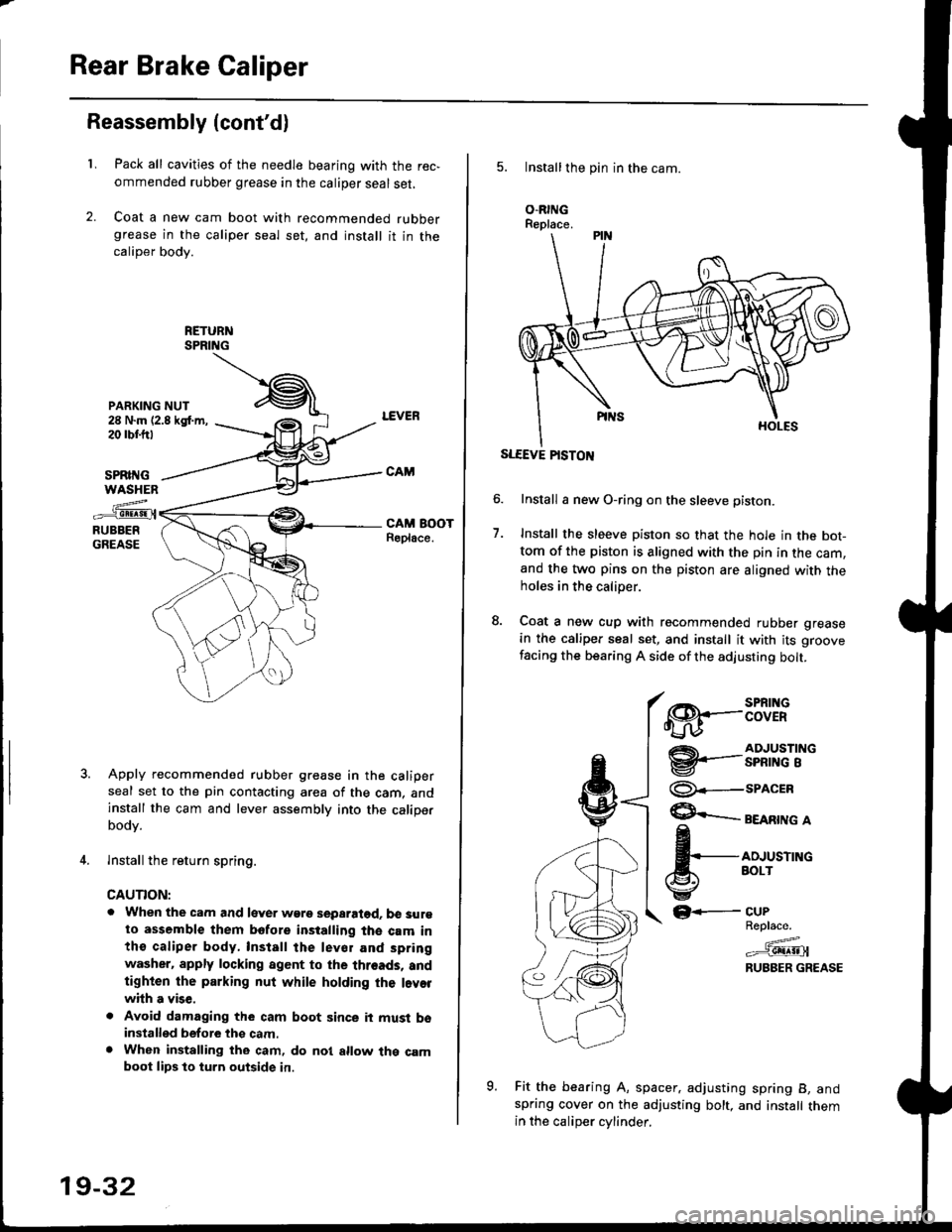
PARKING NUT28 N.m (2.8 kgt m,20 rbr.trt
Pack all cavities of the needle bearing with the rec,
ommended rubber grease in the caliper seal set,
Coat a new cam boot with recommended rubbergrease in the caliper seal set, and install it in thecaliper body.
SPRII{GWASHEN
z..-_e!!!9!.{RUBBERGREASE
Apply recommended rubber grease in the caliperseal set to the pin contacting area of the cam, andinstall the cam and lever assembly into the caliperbodv.
lnstall the return spring.
CAUTION:
. When the cam and lever wgre separatod. b€ surgto assemble them bofore installing the cam inthe caliper body, Install the lev€r and spring
washer. apply locking agent to the threads, andtighten the parking nut while holding the l.vorwhh a vise,
. Avoid damaging the cam boot since it must bsinstalled before thg cam.. When installing the cam, do nol allow the camboot lips lo turn outside in.
19-32
5. Installthe pin in the cam.
O.RINGReplace.
SLEEVE PISTON
Install a new O-ring on the sleeve pisron.
Install the sleeve piston so that the hole in the bot-tom of the piston is aligned with the pin in the cam,and the two pins on the piston are aligned with theholes in the calioer.
Coat a new cup with recommended rubber grease
in the caliper seal set, and install it with its groove
facing the bearing A side of the adjusting bolt.
7.
€8.--:BTif
@'-.-3nfi""'i"
@--seacrn
$ eeenrne a
fi,*,*^"
GF-
Fit the bearing A, spacer. adjusting spring B, andspring cover on the adjusting bolt, and install themin the caliDer cvlinder.
CUPReplace.
=^.#-g!!!!!Jl
RUBBER GREASE
o