Page 1703 of 2189
Driver's Window Motor Test
Motor Test:
l. Remove the driver's door panel (see section 20).
Terminal side of male terminals
Disconnect the 4P connector from the motor.
Test the motor in each direction by connecting bat-
tery power and ground according to the table.
CAUTION: When th€ molor stops running, discon-
n€ct one lead immediat€ly.
4. lf the motor does not run or fails to run smoothlv.
reDlace it.
3.
l.,,
Terminal
;."t1."
-_l\1
UPo@
DOWNoo
Puls€r Test:
5. Connect the test leads of an analog ohmmeter to the
No. 3 and No. 4 terminals.
6. Run the motor by connecting power and ground to
the No. 1 and No.2 terminals. The ohmmeter needle
should move back and forth alternately.
23-233
Page 1704 of 2189
Power Windows
Passenger's Window Motor Test
Front:
1. Remove the passenger's door panel (see section
20t.
2. Disconnect the 2P connsctor from the window
moIor.
2P CONNECTOR
\
Terminal side ot msleterminals
3. Check window motor operation by connecting power
and ground according to the table.
CAUTION: When the motor stops running. dbcon-
nest ono load immadiatoly.
4. lf the motor doas not run or fails to run smoothly.
replace it.
Terminal
;;,r";--lI
UP@o
DOWN@
23-234
Re!r:
1. Remove the passenger's door panel {see section
20).
2. Disconnect the 2P connectof from the window
motor.
NOTE: The illustration shows the right rear window
motor; the left rear window motor is symmetrical.
2P CONNECTOR
3. Check window motor operation by connecting power
and ground according to the table.
GAUTION: Whon the motor ctops running, discon-
nact one lead immodiatoly.
4. lJ the moto. does not run or fails to run smoothly.
rcDlace it,
Terminal
DI;t;;---l
UPo@
DOWN@
Page 1707 of 2189

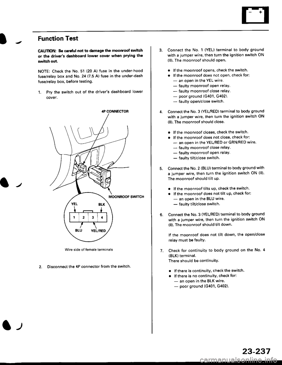
Funstion Test
CAUTION: Bo careful not to damago the moonroof switch
or ths driv6r's dashboard lowsr cover when prying the
3witch out.
NOTE: Check the No. 51 (20 Al fuse in the under-hood
tuse/relay box and No.24 (7.5 A) fuse in the under-dash
fuse/relay box, before testing.
1. Prv the switch out of the driver's dashboard lower
cover.
swtTcH
Wire side of female terminals
2. Disconnect the 4P connector from the switch
4P CONNECTOR
l-t
23-237
Connect the No. 1 (YELI terminal to body ground
with a jumper wire, then turn the ignition switch ON
(ll). The moonroof should open.
. lf the moonroot opens, check the switch.
. lf the moonroot does not open, check for:
- an open in the YEL wire.
- faulty moonroof open relay.
- faulty moonroof close relay,
- poor ground (G401, G402).- fa u lty open/close switch.
Connect the No. 3 (YELnED) terminal to body ground
with a jumper wire. then turn the ignition switch ON
(ll). The moonroof should close.
. lf the moonroof closes. check the switch.
. lf the moonrool does not close, check for:
- an open in the YEURED or GRN/RED wire'
- faulty moonroof close relaY.
- faulty moonroot oPen relaY.
- faulty tilvclose switch.
Connect the No. 2 (BLU) terminal to body ground with
a jumper wire, then turn the ignition switch oN (ll).
The moonroof should tilt up.
. lf the moonroof tilts up, checkthe switch.
. lf the moonroof does nottilt up, checkfor:
- an open in the BLU wire.
- taulty tilvclose switch
Connect the No. 3 (YEURED) terminal to bodY ground
with a jumper wire, then turn the ignition switch ON
(ll), The moonroof should tilt down.
lf the moonroof does not tilt down, the open/close
relay must be taulty.
Check for continuity to body ground on the No. 4
{BLK}terminal.
There should be continuity.
. lf there is continuity, check the switch
. lf there is no continuity, check for:
- an open in the BLK wire
- poor ground (G401, G402).
6.
7.
Page 1708 of 2189
Moonroof
1.
Switch Test
Carefully remove the switch from the driver's dash-
board lower cover {see page 23-205}.
Check for continuitv between the terminals in each
switch position according to the table.
Terminal
t*',*-----__\I234
ut-t-
OPENo--o
CLOSEo---o
TILTo--o
23-234
Motor Test
'1.Remove the headliner (see section 20).
Disconnect the 2P connector from the moonroof
motor.
Terminal side of male terminals
Check the motor by connecting power and ground
according to the table.
4. lf the motor does not run, replace it (see section 20).
NOTE: See Closing Force Check in section 20 for
motor clutch test.
\_____lTr1
Position
,l
OPENo@
CLOSE@
Page 1709 of 2189
Open/Close-Tilt/Close Switch Test
1. Remove the headliner (see section 20).
2. Disconnect the 2P and 4P connectors from the moon-
roof motor and the switch.
3. Check for continuity between the terminals in each
switch position according to the table.
Terminal side of male terminals
Terminal
*r*"-
-\123
CLOSE .* TILTo--oo---o
CLOSE ..--. OPENo--o
4. lf there is no continuity, adiust or replace the switch'
l-t
23-239
Page 1710 of 2189
Gruise Control
Component Location Index
MAIN SWITCHTesVReplacement,page 23-242CABLE REELReplacement, section 24
BRAKE SWITCH, fest, page 23-244. Pedal Height Adjustment,section 19CRUISE CONTROI. UNITInput Test, page 23-240
swrTcH {M/T). Test. page 23-244. Clutch Pedal Adjustment,section 12
atfSWTTCH. Test, page 23-154' Replac€ment, page 23-'155
ACTUATOR CABLEAdjustment, page 23-246
VACUUM TANK
TOR ASSEMBLY. Test, pag€ 23-245. Replacement, page 23-246. Solenoid Test, page 23-247' Disassembly, page 23-248
23-240
Page 1712 of 2189
Cruise Control
Gontrol Unit Input Test
SRS components are located in this area. Review the SRS component locations, precautions, and procedures in the SRSsection (24) before performing repairs or service.
1. Remove the driver's dashboard lower cover and knee bolster (see section 20).
2. Disconnect the l4P connector from the control unit.
3. Inspect the connector and socket terminals to be sure they are all making good contact.
lf the terminals are bent, loose, or corroded, repair them as necessary, and recheck the system.lf the terminals look OK, make the following inpul tests at the connecror.- lf any test indicates a problem, find and correct the cause, then recheck the system,- lf all the input tests prove OK, the control unit must be faulty; replace it.
14P CONNECTOR
CRUISE CONTROL UNIT
*i '99 00 models with A/T
23-242
GRN/WHT LT GRN/RED LT GRN/BI-K
8LU/GRN*
Wire side of female terminals
Page 1713 of 2189

)
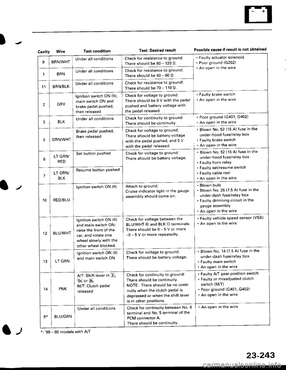
CavityWireTest conditionTest: Desired resultPossible cause if result is not obtained
BRNA/VHTUnder all conditionsCheck for resistance to ground:
There should be 80 - 120 O.
Fau lty actuator solenoid
Poor ground (G202)
An open in the wire
1BRNUnder all conditionsCheck for resistance to ground:
There should be 40 - 60 0.
11BRN/BLKUnder all conditionsCheck for resistance to ground:
There should be 70 - 110 0.
2GRY
lgn jtion switch ON (ll),
main switch ON and
brake pedal pushed,
then released
Check for voltage to ground:
There should be 0 V with the Pedal
pushed and battery voltage with
the pedal released.
'Faulty brake switch
. An open In the wlre
3BLKU nderall conditionsCheck for continuitY to groundl
There should be continuity
' Poor ground (G401, G402)
. An open in the wire
5GRNA,A/HT
Brake pedal pushed,
then released
Check for voltage to groundl
There should be batterY voltage
with the Pedal Pushed. and 0 V
with the pedal released
. Blown No. 52 (15 A) fuse in the
under-hood fuse/relaY box
. Faulty brake switch. An open in the wire
LT GRN/
RED
Set button pushedCheck for voltage to ground:
There should be batterY voltage.
Blown No. 52 (15 A) fuse in the
under-hood fuse/relaY box
Faulty horn relay
Faulty sevresume switch
Faulty cable reel
An open in the wire7LT GRN/
BLK
Resume button Pushed
10RED/BLU
lgnition switch ON (ll)Attach to ground:
Cruise indicator light in the gauge
assembly should come on.
Blown bulb
Blown No. 25 (7.5 A) fuse in the
under dash fuse/relay box
Faulty dimming circuit in the
gauge assemDly
An open in the wire
BLU,A/VHT
lgnition switch ON (ll)
and main swilch ON;
raise the front of the
car, and rotate one
wheel slowly with the
other wheel blocked.
Check for voltage between the
BLUMHT @ and BLK O terminals:
There should be 0- 5 V or more
-0- 5 V or more repeatedlY
. Faulty vehicle speed sensor {VSS)
. An open in the wire
LT GRN
lgnition switch ON (ll)
and main switch ON
Check for voltage to ground:
There should be batterY voltage.
Blown No. 14 (7.5 A)fuse in the
under-dash luse/relaY box
Faulty main switch
An open in the wire
14PNK
A,T: Shift lever in E,
ojorE
M/T: Clutch pedal
released
Check for continuity to ground:
There should be continuity.
NOTE: There should be no conti-
nuity when the clutch Pedal is
depressed or when the shift lever
is in other positions.
Faulty A/f gear position switch
Faulty or misadjusted clutch
switch (M/T)
Poor ground (G401, G402)
An open in the wire
BLU/GRN
Under all conditionsCheck for continuity between No. I
terminal and No. 5 terminal of the
PCM connector A.
There should be continuity
. An open in the wire
*: '99 - 00 models with A,/Tl-,
23-243