1999 HONDA CIVIC crank
[x] Cancel search: crankPage 1562 of 2189
Battery
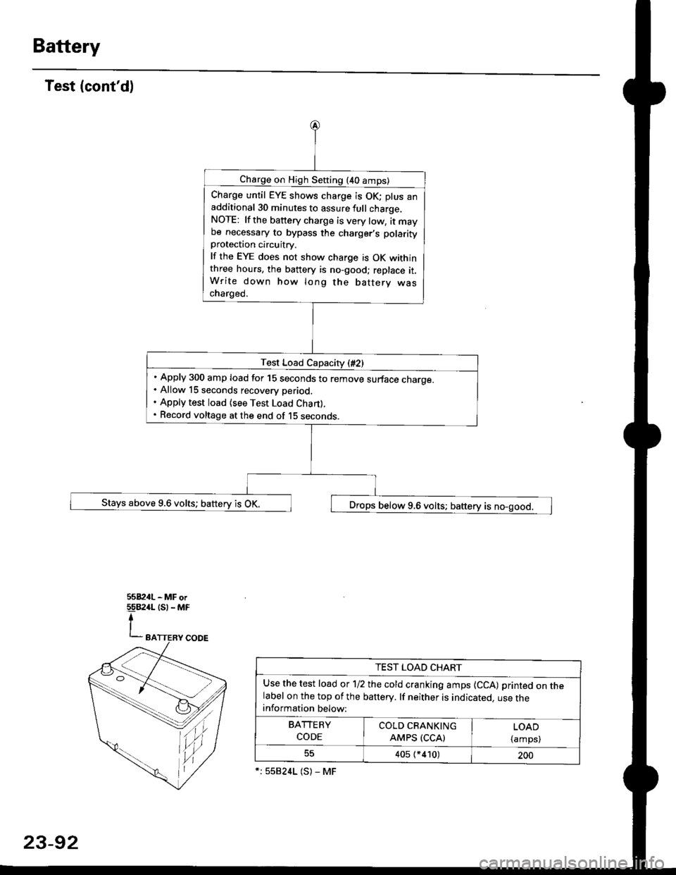
Test (cont'd)
Charge on High Sefting (40 amps)
Charge until EYE shows charge is OK; plus anadditional 30 minutes to assure full charge.NOTE: lf the battery charge is very tow, it maybe necessary to bypass the charger,s polarityprotection circuitry.
lf the EYE does not show charge is OK withinthree hours, the battery is no-good; replace it.Write down how long the battery wascharged.
Test Load Capacity (#2)
Apply 300 amp load for 15 seconds to remove surface charoe.Allow 15 seconds recovery period.
Apply test load {see Test Load Chan).
Record voltage at the end of 15 seconos.
Stays above 9.6 volts; battery is OK. ,] Drops below 9.6 volts; baftery is no-good.
tu,
TEST LOAD CHART
Use the test load or 1/2 the cold cranking amps {CCA) printed on thelabel on the top of the banery. lf neither is indicated. use theinformation below:
BArrERy coLb@
coDE I AMps (ccAl | {amps)
405 (*410)200
*:558241 (S) - MF
23-92
Page 1565 of 2189
-Starter Test
NOTE; The air temoerature must be between 59 and
100'F (15 and 38"C) before testing.
Recommended Procedure:
. Use a staner system tester.
. Connect and operate the equipment in accordance
with the manufacturer's instructions.
. Test and troubleshoot as described,
Alternate Procedurg:
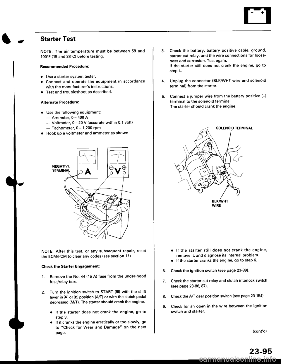
. Use the following equipment:- Ammeter, 0 - 400 A
- Voltmeter, 0 - 20 V (accurate within 0.1 volt)
- Tachometer, 0 - 1,200 rpm
. Hook up a voltmeter and ammeter as shown.
NEGATIVETERMINAL
NOTE: After this test, or any subsequent repair. reset
the ECM/PCM to clear any codes (see section l1)
Check the Start€r Engagemont:
1. Remove the No. 44 (15 A) fuse from the under-hood
fuse/relay box,
2. Turn the ignition switch to START (llll with the shift
lever in E or E position (rVT) or with the clutch pedal
depressed {M/T). The starter should crank the engine.
. lf the starter does not crank the engine, go to
step 3.
. lf itcranksthe engineerraticallyortooslowly, go
to "Check for Wear and Damage" on the next
page.
Check the battery. battery positive cable, ground,
starter cut relay, and the wire connections for loose-
ness and corrosion, Test again.
lf the starter still does not crank the engine, go to
step 4,
Unplug the connector (BLK,/WHT wire and solenoid
terminal) from the starter,
Connect a jumper wire from the battery positive (+)
terminal to the solenoid terminal.
The starter should crank the engine.
. lf the starter still does not crank the engine,
remove it, and diagnose its internal problem
. lf the startercranksthe engine, goto step 6.
Check the ignition switch (see page 23-891.
Check the starter cut relay and clutch interlock switch
(see page 23-86,87).
Check the A/f gear position switch (see page 23-154).
Check for an open in the wire between the ignition
switch and starter.
7.
(cont'd)
23-95
9.
Page 1566 of 2189
Starting System
Starter Test lcont'dl
Ch€ck tor Wear and Damage
The starter should crank the engine smoothly and
steadily, lf the starter engages. but cranks the engine
erratically, remove it, and inspect the starter drive gear
and torque converter or flywheel ring gear for damage.
. Check the drive gear overrunning clutch for binding
or slipping when the armature is rotated with the
drive gear held,- lf damaged. replace the gears.
Check Cranking Voltsge and Curr€nt Draw
Cranking voltage should be no less than 8.5 volts.
Current draw should be no more than 350 amperes.
lf cranking voltage is too low, or current draw too high,
check for;
. dead or low batterv.
. open circuit in starter armature commutator seg-
ments,
. starter armature dragging.
. shorted armature winding.
o excessive drag in engine.
Check Cranking rpm
Engine speed during cranking should be above 100 rpm,
lf speed is too low, check for:
. loose battery or stanerterminals.
. excessively worn starter brushes,
. open circuit in commutator segments.
o dirty or damaged helical spline or drive gear.
. defective drive gear overrunning clutch.
Check Siarter Disengag€ment
With the shift lever in El or @ position (A/T) or with the
clutch pedal depressed (M/T), turn the ignition switch to
START (lll), and release to ON (ll).
The starter drive gear should disengage from the torque
converter or flywheel ring gear when you release the
Key.
lf the drive gear hangs up on the torque converter or fly-
wheel ring gear, check for:
. solenoid plunger and switch malfunction,
. dirty drive gear assembly or damaged overrunning
clutch.
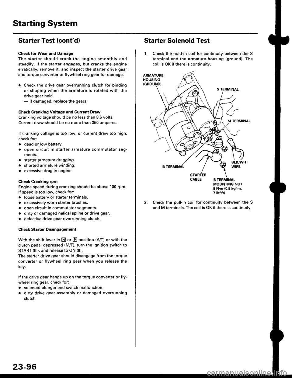
Starter Solenoid Test
1. Check the hold-in coil for continuitv between the S
terminal and the armature housing (ground). The
coil is OK if there is continuitv,
ARMATUREHOUSING(GROUND)
S TERMINAL
M TERMINAL
B TERMINAL
STARTERCAELE B TERMINALMOUNTING NUTI N.m {0.9 kgf.m,7 tbf.ft)
Check the pull-in coil for continuity between the S
and M terminals. The coil is OK if there is continuity.
Page 1573 of 2189
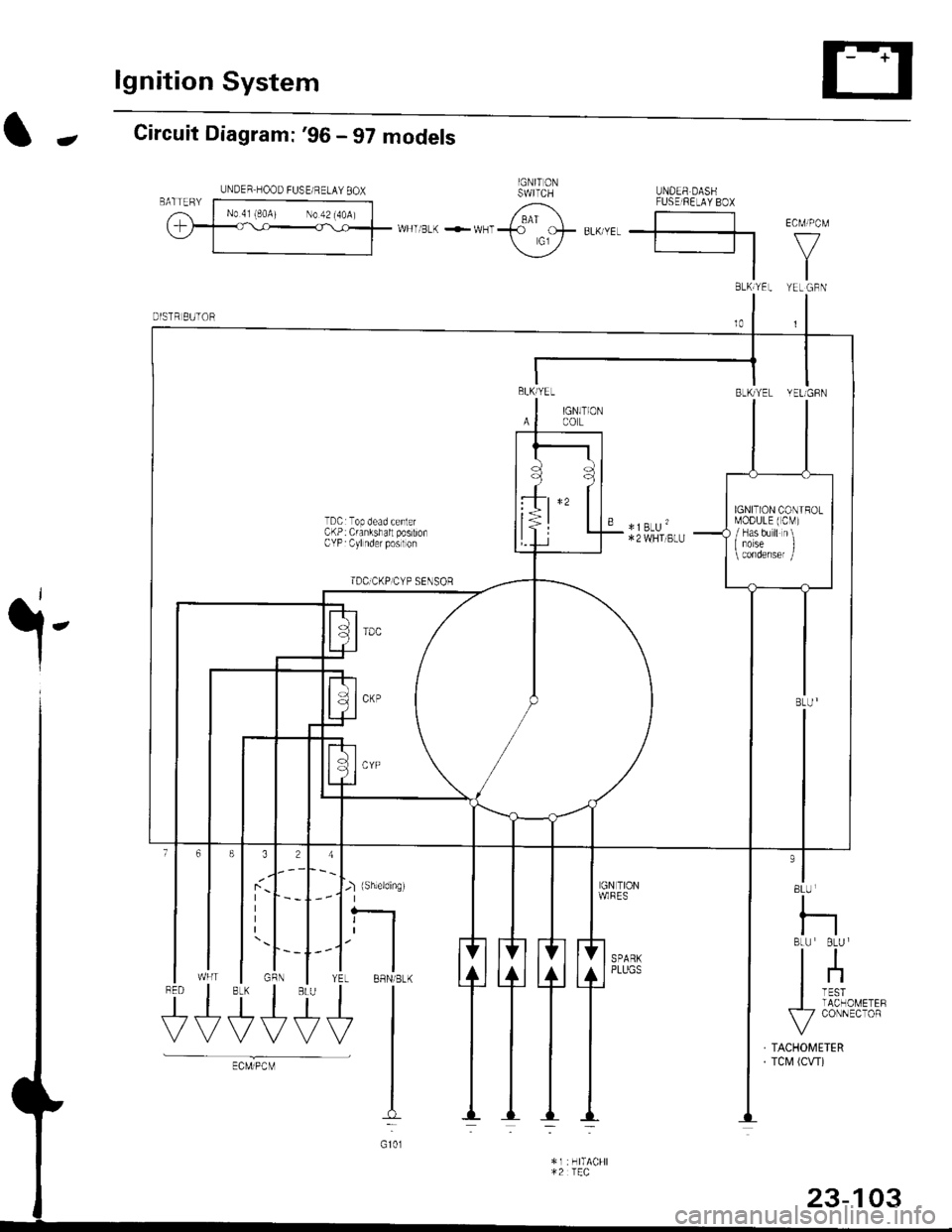
lgnition System
-Circuit Diagram: '96 - 97 models
.i-
8LU
I
nBLU BLU I
tl
lnI TESTI TACHOMETEF\-7 CONNECTOR
TACHOMETERTCM (CW)
J-) {sh,eldinsr't I
tfYEL BBN/BLK
+l
I:
G101
$t+++
UNDER HOOD FUSE/ RELAY 8OX
BLh TEL YEL GBN
BLKlYEL
IAl
BLK/YEL YELIGFN
IGN]TIONCOL
TDCrTop dead cenlerCKP: Crankshall postionCYP Cylnder poslon
TDC]CKP]CYP SENSoR
" *]BLU'*2 WHI BLU
IGNITION CONIROLMODULE (CM)
/ Has b'r ll n\I iorse I
rUSE FE-AV BO}
*u r-. .-*---{<9ot # u,,."r. | |
\j/ El v
tl
23-103
Page 1595 of 2189
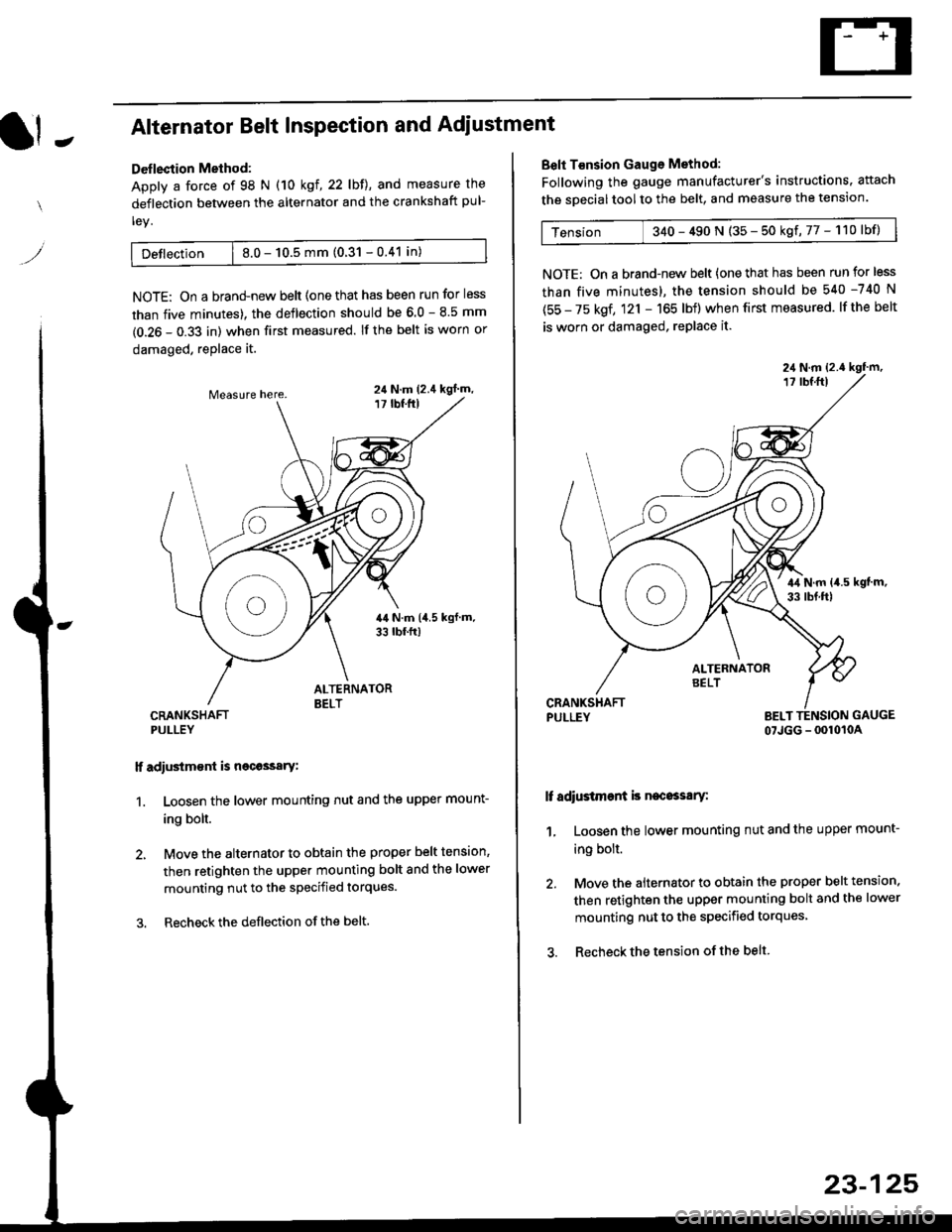
It -Alternator Belt Inspection and Adiustment
Deflection Method:
Apply a force of 98 N (10 kgl,22lbll, and measure the
deflection between the alternator and the crankshaft pul-
ley.
Detlection | 8.0 - 10.5 mm (0.31 - 0.41 in)
NOTE: On a brand-new belt {one that has been run for less
than five minutes). the deflection should be 6.0 - 8.5 mm
(0.26 - 0.33 in) when first measured. If the belt is worn or
damaged, replace it.
CRANKSHAFTPULLEY
lf adiustm€nt is necossary:
1. Loosen the lower mounting nut and the upper mount-
ing bolt.
2, Move the alternator to obtain the proper belt tension,
then retighten the upper mounting bolt and the lower
mounting nut to the specified torques.
3. Recheckthe deflection ofthe belt.
24 N.m (2.4 kgl m,
Belt T€nsion Gauge Method:
Following the gauge manufacturer's instructions. attach
the soecial tool to the belt, and measure the tension.
Tension 340 - 490 N (35 - 50 kgf,77 - 110lbf)
NOTE: On a brand-new belt {one that has been run for less
than five minutes), the tension should be 540 -740 N
(55 - 75 kgf, 121 - 165 lbf) when first measured. lf the belt
is worn or damaged, replace it.
PULLEY BELT TENSION GAUGE
07JGG - 0010104
It adiustment is necossary:
1, Loosen the lower mounting nut and the upper mount-
ing bolt.
2. Move the alternator to obtain the proper belt tension.
then retighten the upper mounting bolt and the lower
mounting nut to the specified torques
3. Recheck the tension of the belt
23-125
Page 1829 of 2189
In the "OHMS" range, the DVOM will measure
resistance between two points along a circuit.
Low resistance means good continuity.
Diodes and solid-state devices in a circuit can
make a DVOM give a false reading. To check
a reading, reverse the leads, and take a
second reading. lf the readings differ, the
component is affecting lhe measurement.
Jumper Wire
Use a jumper wire to bypass an open circuit.
A iumper wire is made up ot an in-line fuse
holder connected to a set of test leads. lt
should have a five amoere fuse. Never
connect a jumper wire across a short circuit.
The direct battery short will blow the fuse.
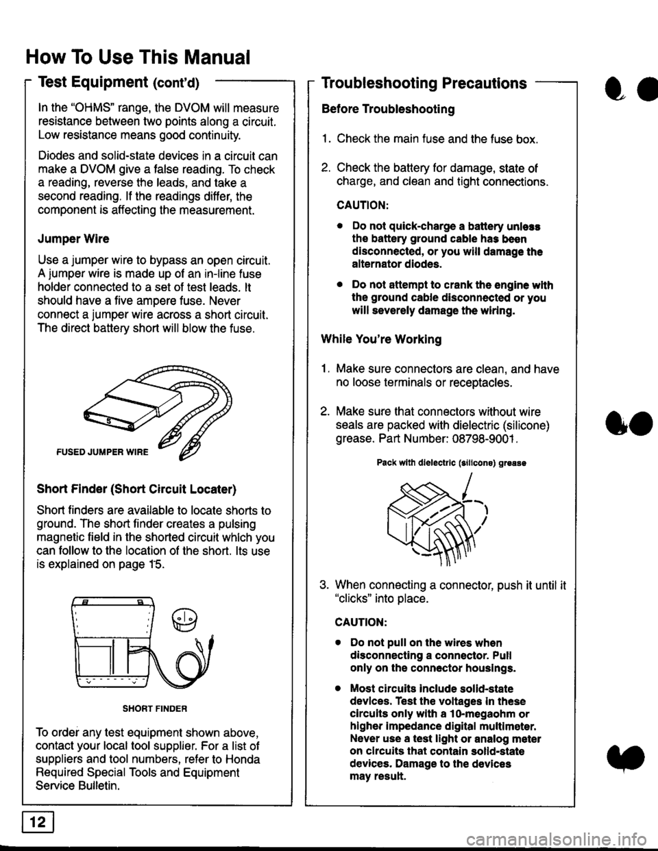
Short Finder (Short Circuit Locater)
Short finders are available to locale shorts to
ground. The short tinder creates a pulsing
magnetic field in the shorted circuit whlch you
can follow to the location of the short. lts use
is explained on page 15.
SHORT FINDER
To ordei any test equipment shown above,
contact your local tool supplier. For a list of
suppliers and tool numbers, refer to Honda
Required Special Tools and Equipment
Service Bulletin.
How To Use This Manual
Test Equipment (cont'd)
oa
Troubleshooting Precautions
Before Troubleshooting
1. Check the main fuse and the fuse box.
2. Check the battery for damage, state of
charge, and clean and tight connections.
CAUTION:
. Do not quick-charge a battery unlers
the battery ground cable has been
disconnected, or you will damage the
alternator diodes.
. Do not attempt to crank the engine wlth
the ground cable disconnected or you
will severely damage the wiring.
While You're Working
1. Make sure connectors are clean, and have
no loose terminals or receptacles.
2. Make sure lhat connectors without wire
seals are packed with dielectric (silicone)
grease. Part Number: 08798-9001 .
Pack wllh dlelectrlc (sillcons) greass
When connecting a connector, push it until it"clicks" into place.
Do not pull on the wires when
disconnecting a connector. Pull
only on the connector houslngs.
Most circuits Include solid-state
devlces. Test the voltages In these
circuits only with a lo-megaohm or
higher impedance digital multlm6ter.
Never use a test light or analog meter
on chcuits that contain solld-state
devices. Damage to the devices
may result.
oo
Page 1858 of 2189
----" A/T -----t
DRIVEN PULLEY , ^.,.
;iftTBilis'".f l5Ftr,.""_
co'rinienixnn '. Pase 23'2
SPEED SENSOR ; .'-\.SHIELD 'F--.1
TDC/CKP/CYPSENSORSHIELDPage 20
ll
r_:.-i
23-13
t1
23- l4
tl
PRIMARY SECONDARYHO2S HO2SSHIELD SHIELDPages 23-8, Pages 23-9,23-10. and 23-11. and
--- CW ----.
TRANSMISSION ;CONTROLMODULE(TCM) ,Page 39-5 :PHO|O 121vlEw 69r____1 ,
tt:
tt:L----J,
. D16Y8engine
SECONDARY .
HO2S :SHIELD ;Page 23-11
l. - -..1 ;
tt:(D16Y/i D15Y8)Page 39-1
l.--.1
1l
r:--iBFN/BLKARN/BLK
A4
6FN/BLK' EFN/BI
i i srco"oo"t :' I GEAR SHAFT
I I Or MAtN!'tAt I. II SPEED SENSOR '
CW. - D16Y8 -, engine: N SENSoR SHTELD ,
i !i?il3li*u,, i
CWSHIELD :Page39-4,
CRANK-SHAFTSPEEDFLUCTU-ATION(cKF)SENSORPage 23-2
tl
ll
;I;..
26
i xNocx' SENSOR, (KS)' SHIELD
, Fage zJ-5
: F--.1
:ll
iilr-:i
----:.--------:
c442(Terminals 18-20)
c10.1 PHofo 125\HOTO 21 VIEW 54vtEw 29
'----- cw ----'
DRIVE
BFN/BLK
PULLEY :SPEEDSENSORSHIELDPage 39-4 :
1.---{ :I t;
cl30Oermlnal8'l-10)
vtEw 52
14-'�,
Page 1969 of 2189
Brake System Indicator Light (cont'd)
- How the Circuit Works
The brake system indicator light comes on to alert
the driver that the parking brake is applied, or that
the brake fluid level is low. lt also comes on as a
bulb test when the engine is cranked.
Parking Brake
With the ignition switch in ON (ll) or START (lll),
voltage is applied through fuse 25 to the brake
system light. When you apply the parking brake, the
switch closes and provides a ground for the light.
The light then comes on to remind you that the
parking brake is applied.
Brake Fluid Level
With the ignition switch in ON (ll) or START (lll),
voltage is applied through fuse 25 to the brake
system light. lf the brake fluid level is low, the brake
fluid level switch closes, providing ground to the
circuit. The brake system light then comes on,
alerting the d verto a low brake fluid level in the
brake master cylinder. (Check brake pad wear
before you add fluid).
Bulb Check
With the ignition switch in START (lll) and clutch
pedal depressed or A'lT gear selector in PARK (P)
or NEUTRAL (N), voltage is applied through fuse 31
to the brake bulb check circuit. The brake bulb
check circuit closes, allowing current to flow through
the brake system light and bulb check circuit to
ground. The brake system light then comes on to
test the bulb.
Refer to the Service Manual (Section 23, Electrical)
for specific tests or troubleshooting procedures.
71-2
a
\fa