Page 1854 of 2189
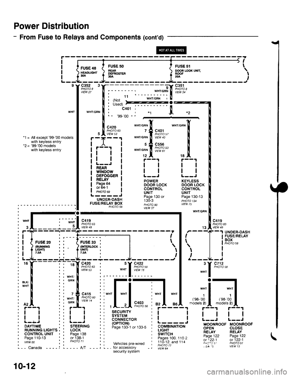
Power Distribution
- From Fuse to Relays and Components (cont'd)
FUSE 48HEAOL|SHT30A
c3s2 3
vtEw 27
WTIT/GFN
FUSF 50FEAFDEFBOSTEF30A
ooon r,ooxuxn \RooF -' I204
I
I
I
I
5t
FusE sr t
9l
;:$*fiit"rl.ru'"'""
I i*il
:::*ffi,
""'_[
tallt r--1 r--1
l-=Ji llll;i'ifr'ilrowi | | | |NEAN
DEFOGGER: L--J L--J
!EuI. ! powen KEYLEss
3g9F I oocin iocx DooR LocKI CONTROL CONTROLPHorobs ! Uttf UN|TL----J ii"j- , "n ^.UNDER-DASH r:d.r ppdro,uFUSETRELAY Box ;;;; "" ,!Fw /); - - - - - - ' - - - - - - - - - - I I P4atasa ;;"; i,
:-;-ry wHr/GFN
: I .-.-.i. -", I '-': :-'I "o''. I l "ott
i
";L____j_lU*?,?"
| .,"Iii;n*
: f'4. ii ;f' ii ,L-.-Ii"?,%' ;f5-"i4.-"'";5-{"'"r'!|L1
:! ! ::! ! :; 3$3i'9,1" r! ! I | | |
i l- l-
- - -
_:-
- ---------1 - - - - - - -
i I r'
- -
T
-
I F$r".',lP,XiI
ii{*"..0 ,' 1;;;il--l l | leox
i! ipp ii liuir'-*i |
')l 'l
l i' r--t-----'-.r--rL--------J- -------t I /---L-I
i
"
l-----l i ::[ir:;?:' i ::[?:+: |
"""1
'*'
i[.iiilr-il[-j,*---]d;1.*-;il;1,
:l I r:l I i: ts6'""?cro* i! ! L--i r--J
i ilr--,.ir...^.._^i I
'rr6-;i."
i: !:lJ',"#,",,*. i i.itc-,tr# Bgg,FooF u-oorinoor' RUNN|NG LrcHrs , ' LocK ; : ; !!gEr_.. ;;,1'y RELAYi cournol^urtr , i pase^138 :: i Swircn- -- Fj.Ti, pase 122, Paoe 110-13 or'138-1 Paoes 100. 110 2 -:Y;^:':;;;''"" :i ;hoi;,; ;: vehicrespre_wired ;!id-?iXioii.' glj:,';: ffl?3;1i,-- canada ----r l----A,/T ---,.-. for accessory -, |;r"*ir" .n 5 vtEvtl 13
10-12
secu.ity system
Page 1865 of 2189
Ground Distribution (cont'd)
1
- G551
Page
I
I
'96-'98 Models:
DRIVER'SwtNDowMOTOR
NOTE: Wires shown without color codes are black.
4
12091
I
I
c633
oRrvER'sDOOR LOCKACTUATORPage 130-1or 130-3
tl
tl
:f ;'*"
.--a ----
sl)
POWER WINDOWMASTER SWITCHPages 120, 120-1,120-2, and 120-3PHO|O AAvlEW 36
tl
tlL-----J
POWERDOORLOCKCONTROLUNITPage 130or 130-3
vlEW3/
tl
tl
4
c556
vtEw 61
8(SedanA4)
DRIVER'SDOORLOCKswrTcHPage 130or 130-3
tl
tl
,I
'-.o -.o -
POWERMIRRORswrTcHPage 141vlEw 33
ll
tl
4(withdefogger 2)
G55t
14-8
Page 1873 of 2189
lgnition System
- All Dl685 engines; All '99-'00 Models except Dl6Y5 with M/T
NOTE: For Service Check Connector details, see page 24-4 (except D1685) or 25-4 (D1685).
STEERINGLOCKPOWERTRAIN
lm- sii.- s*- iffffiEgr
I '8f", '3#n '3#n | (Pcn' or EcM)
L------ -----J Wro 86
',L_I__J,
!l---+--l !
'i---
j----i'
fl '","?siii,xl
I I I
i*n"'."
-"1 "-l '-l *"-^lr";J
I I I ='i.{i31i",,-
All except D1685D1685
gLK.Yer t
u l9f#'
fi
"*1,[
F,*';.,
!'T-f*-'i"i! {F+ Distdbution,
LJ_gg'n'_
i.x,r
9'x*"
-.t
iF--Hs-,mT-l
ll pase lGi. I
l( FUsEe I
!Lig::___J
.I UNDER-I DASH
a FUSE/
! RELAY- BOX
1 Y C419 UNDER-^,ol',lill,l?"u' rlir?IA) RELAYBOX
.t0
BLKI/EL
10(D16Y7/D16Y8 s)
c101
PHO|O 142 lA1685)vlEw 2a
c120
vtEw 29OFN/ALULT BLU orALU/GRN
BLU,^VEL
c120
vtEw 29
ELKWHT/BLU
7
FED
c21c9
ALK
c30
;;--;;---o;;;lSensor Sonsor Sensor I
POWERTRAINor ENGINECONTROLMODULE(PCM or ECM)
ground ground gtound
L ------ -----J PHoro 36
Sec!l|dary
Sparh Plugs
20-2
Page 1877 of 2189
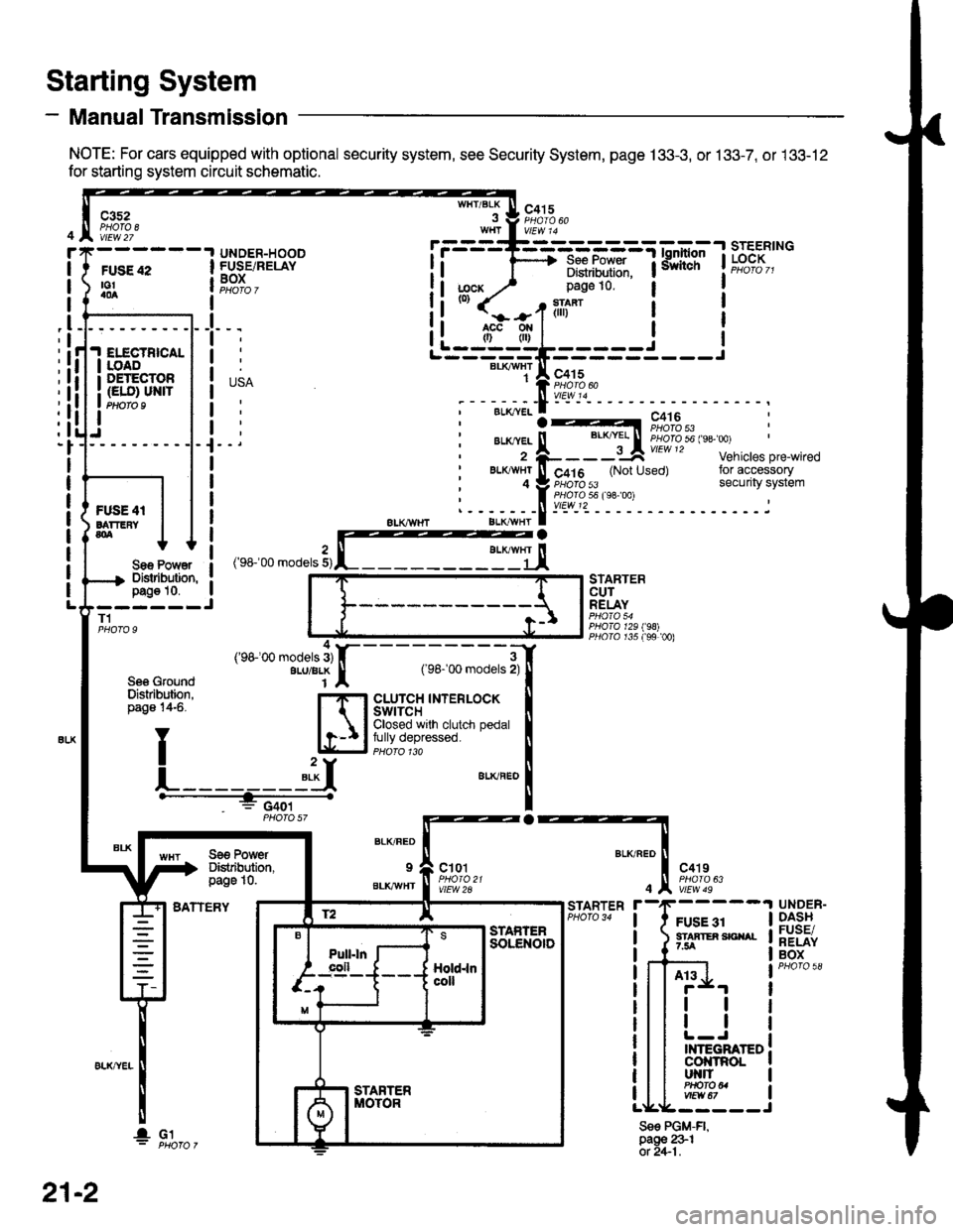
- Manual Transmission
NOTE: For cars equipped with optional security system, see Security System, page 133-3, or 133-7, or 133-12
for starting system circuit schematic.
Starting System
c3s2PHOTA 8vtEw 27
WHT/BLKc415
FUSE 42to!a0a
UNDER-HOODFUSE/RELAYBOXI
I
I
_l
IELECTBICALIOADDETECTOR(ELO) UN|TPtloro I
Sae Po'/Y€rDislibution,pag€ 10.------JT1
Se6 GroundDislribution,page 14-6.
BATTERY
STARTERCUTRELAY
PHO|A 129198)PllO|O r35 f99 00)
a
BLK/FED
9
BLKAVHT
ct01
vlEW 2A
c4't9
vtEw 49
FUSE 31STAATER SICIIAL7.5A
STARTER
4
Sse PGM-FI,page 231ot 2+1.
UNDER-DASHFUSE/RELAYBOX
At3
tl
tl
INTEGRATEDcol{tRoLut{llPHO|O U
r.------T-------------=;-*^:-lsrEERtNG
I i 1'----> R*.|?xf: iiiliffi' t"t%?I,,I Distribulion.1j;cx y' page 10.(0)
it-jtr'tl i
j
r---_-_€rx^,:jF;f
;-;:.==:t A r,+lo'tii:,J?"""
;--;*;.-f -- ^.:---.---1--
,'rr-'OO .o0"," 3,rffiEj,
---;;;;i[
cLUrcH TNTERLOCK tClosed wrlh clutch pedal Ifully depressed. llPHoro 1ra I"**"
!
Se€ PowerDistibution,page 10.
4('98100 models 3)ALU/BLK
f2 lE--r.---?q_l srAFrEn
21-2
I- G1
Page 1923 of 2189
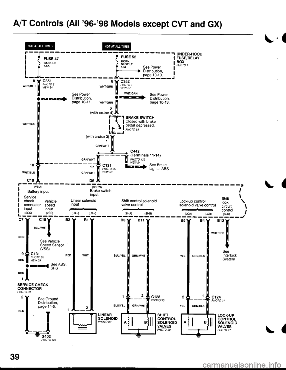
A/T Controls (All '96-'98 Models except CW and GX)
r.(
r5A see power I
--li$"i':,--iL-.At----- __*____..,,53-j"i__8 Y 93^s_1- 8Y C352'"'".u
I iii'i"' ""'o"* | i#?1o.'
ll see power ll wrr cnn See Power
la--- oisirioution, ! -t 6iri,iortion,
[--*
t"*tr*t1,'.':,:;i. wHr GFN lt page 10-13.
,i(with crurse 4) Al"'rl(-1 BRAKE swrrcH
| lClosed.with brake
Ir-I Il,?,|fll,"P'"""oL*--J
c18lr 82
"ar-"t I
I
See VehicleSpeed Sensor(vss)
ct31PHO|O 35vtEw 59
r< See ABs'
UNDER"HOODFUSE/RELAYBOXI
I
I
BFN
9
BFN
o
""il
SERVICE CHECKCONNECTOR
See GroundDistribution,page 14-5.
I
YEL
c124
L__lH:""".: G402
SHIFTCONTROLSOLENOIDVALVES
LOCK-UPCONTROLSOLENOIDVALVES
,. L ---- - - --.#ku" :::::'o f
---------tty"c;11,, l;-,f l;?t?:if,-:;tr *";.!, *"
c10 ,| Ds^'
I Lvou, (SKSV,
! Battery input Brake lwitch I
service nPUt ehin t;;;;i- Vehrcte Linear sotenoid Shift controt sol€noid Lock-up conkol iJ'[
'\
connector speed input valve conhol solenoid vatve controt tliiJ"it \uo trut tconrrol t: (scs) (vss) {Ls}) rLs ) {sHA' {SHB, (LCA) (LCB) {S-U) .--:-'--J
ct28
39
GFN/ALK
(
Page 1931 of 2189
A/T Controls (All GX and All '99-'00 Models except CVI)
a
i-l-;;;
-rffi;----t
H*B'""i
! l r*-* i iflsln- :eepower ii|iii '
L_l____ _-i"utuiF#'i8 Y 93-s_1 SY C3s2 :""'".u I i,i?lol *"'o"n I iffl,1of
ll see eower ll wxrcnl - see power :
@
c131
vlEw 59
See GroundDistribulion,page 14-5. 1
["*
t*,t*;,,
;ffi i-
iilnirir,
Distribution,page 10-5.
,D5
, ry8 SOr)I Power source
BLI(YEL
il
10
WHT/BLU
821
(VBU)
Banery input
Servicecheck Vehicls Linear sol€noidconneclor speednput
' for solenoid valve ; \
Lock-up controlsolenoid valve (valve control circuitShift lock \
c'124
a
inpulinput
{8KSW)Brake switchInput
Shilt control solenoidvalve control
:::l
",:::[""::
. | .ir:Til**'
''lizll:l,,' i*'";l'-.----.'
O rr<( !!e"A65,
""il
SERVICE CHECKCONNECTOR
c12A
LTGRN/
I
SH IFTCONTROLSOLENOIDVALVES
LOCK.UPCONTROLSOLENOIDVALVESL__l+: G402a
il*-
except GX
See Powerr?F.| BRAKE SWTTCH
| | Closed with brake
| 1-I | !;€ja oeo'"""o
39-8
Page 1944 of 2189
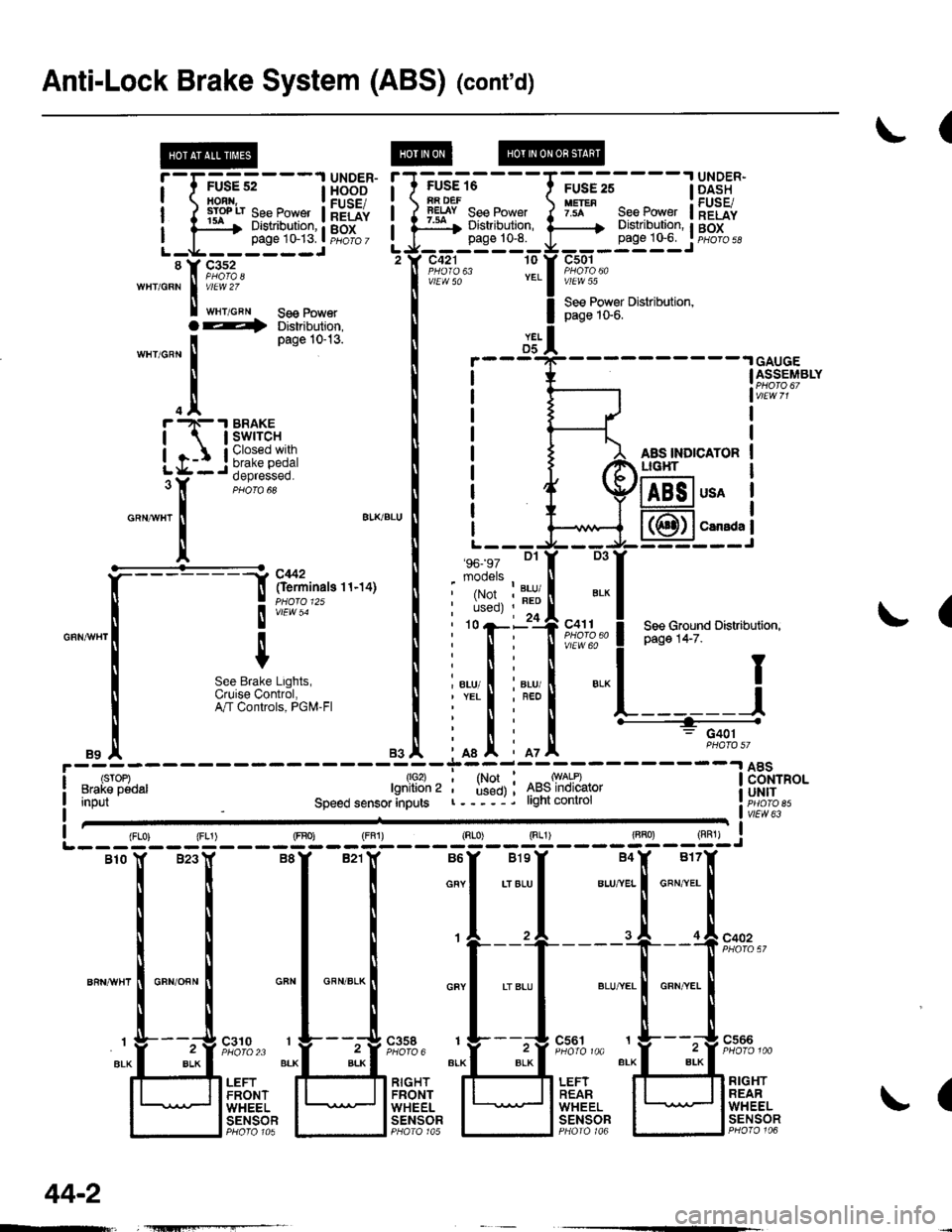
Anti-Lock Brake System (ABS) (cont'd)
(
FUSE 16iA DEFlEtsY See Power:ar Distribution,page 10-8.
c421 10
vlEW 50
'96- 97 Dl
mooels
.I UNDER-
page 1G6. I pHoro 5d
c501
vlEW 55
See Power Distribution,page 1S6.
AAS INDICATORLIG}IT
!'-r;us?;---l H5BE"
ilrryilrfi#ftilHriL-g------JL-g------J'tr F,1%'wHr/GRN I v/El.V 2Z
I t"r,o"" se€ Power
YELD5GAUGEASSEMBLY
usA
CarsdaI
(
D3
', ',i:,tr?""" ! P"g" t+-z".r',
*
! see cround Distributiofl,
".., I i"., I ".-l I;nl
iffit L------J
' n : G401
mI iot
T1*l ^*ry*l:-------l 8Bi"o.' used) ; 4ts5lnolcalor i UH|Tr----j. light conlrol r. iicib ett,"LTfflo",Input
1lo2)lgnition 2
Speed sensor anputsvlEw 63
(
{FLo) {FL1) (FBo) {FF1) (Rr"o) Sg____gT]-__g,l-j
Blo lf B23Y B8Y B21lf B6Y BlsY B4X B17f
i i I i o""l .,",-ul u.,"..1 o"",'.. I
rrttl
| | | I ,l ,l .I of"on"
ll ll I ti
't---'+----"[ --f !'?'%,'
""n*",lo"no""l *"1 *"*-l *"1 .'"."1 *,*.[ "**.I
I r L___t"" " t__t"." 1___!".""
"r.f_ "4::3' ;FJ,;::; ":f3:::1'' "lf-*i":''
t' ,.,Jtri"?r. ll;l]flffi lFli.ft. lU]flqtfl
l l"#tgl I lt5T8?l I lt"F"Ti?l I lt;Tt?f
O--t Distribution,
'n"r,o^n
I
Page 10-13'
.trr -N- .I BRAKE
| | swrrcH
igr:*
o"ntr"r
!
a'KBLU
It
""*[:-l
ftff^"n"o''''ot
I
", I
m;r""#,usi:",
".1
44-2
Page 1957 of 2189
- How the Circuit Works
Battery voltage is supplied through tuse 56 to the
A,/C compressor clutch r€lay contacts at all times.
With the ignition switch in ON (ll), vollage is applied
to the coil of the A,/C compressor clutch relay
through fuse 17. When you push the A,/C switch
ON, and the heater fan switch is in position | , 2, 3,
or 4, a "ground" input is provided to the engine
control module (ECM) or powertrain control module
(PCM) through the l'lC thermostat and the l'lC
pressure switch.
The A,/C compressor clutch relay is grounded by the
engine control module (ECM) or powertrain control
module (PCM). When energized, the A'lC
compressor clutch relay allows battery voltage to
turn on the A,/C comDressor clutch.
The A,/C ON indicator light comes on when the A,/C
system is requested.
A,/C Thermostat
The A'lC thermostat is located on the evaoorator
housing. The A,/C thermostat turns off the A,/C
compressor clutch if the temperature at the
evaporator goes below 3'C (37'F). This prevents
condensation from freezing on the evaporator fins
and blocking the air delivery into the passenger
compartment. The blower motor will keep running
when the sensor turns off the comDressor.
A,/C Pressure Switch
The fuC oressure switch is located in the condenser
outlet line where refrigerant is in a high
temperature/high pressure liquid state. The switch
will sense abnormally high or low pressure, and
open the circuit. This removes ground, and the
compressor will stop running.
Thermal Protectot
The thermal protector, located on the A,/C
compressor, opens and turns the compressor off if it
senses high temperature. Once the compressor
cools, the switch will close and the compressor will
begin running again.
Refer to the Service Manual (Section 22,
Air Conditioning) for specific tests or
troubleshooting procedures.
62-3