Page 910 of 2189
![HONDA CIVIC 1999 6.G Workshop Manual \a
PCM CONNECTOR D {16P)
14-233
Terminal Numbs]SignalDescriptionMeasuring Conditions/Terminal Voltage
D1VELSecondary gear shaft speed
sensor signal input
Depending on vehicle speed: Pulsing signal
Whe HONDA CIVIC 1999 6.G Workshop Manual \a
PCM CONNECTOR D {16P)
14-233
Terminal Numbs]SignalDescriptionMeasuring Conditions/Terminal Voltage
D1VELSecondary gear shaft speed
sensor signal input
Depending on vehicle speed: Pulsing signal
Whe](/manual-img/13/6068/w960_6068-909.png)
\a
PCM CONNECTOR D {16P)
14-233
Terminal Numbs]SignalDescriptionMeasuring Conditions/Terminal Voltage
D1VELSecondary gear shaft speed
sensor signal input
Depending on vehicle speed: Pulsing signal
When vehicle is stoPPed: APProx. 0 V
02SOL INHlnhibitor solenoid controlWith inhibitor solenoid ON: Battery voltage
With inhibitor solenoid OFF: 0 V
D3SH LSMShift control linear solenoid
power supply negative electrode
D4SH LSPShift control linear solenoid
power supply positive electrode
With ignition switch ON (ll): Pulsing signal
D5VB SOLPower supply for solenoid valvesWith ignition switch ON (ll): Baftery voltage
With ignition switch OFF:0 V
D6ATP RA,/T gear position switch E
position input
InEposition:0V
In other than B position; Approx. 10 V
D]VEL SGSecondary gear shaft sPeed
sensor ground
D8Not used
D9Not used
D10NDNDriven pulley speed sensor signal
anput
In other than E and E position: Pulsing signal
D11NDRDriven pulley speed sensor signal
input
ln other than E and E position: Pulsing signal
D12NDR SGDrive pulley speed sensor ground
D13ATP SA,/T gear position switch E
position input
InE position: 0V
In other than E position: Battery voltage
D14D INDD indicator light controlWhen ignition switch is first turned ON (ll):
Battery voltage for two seconds
In E position: Battery voltage
D15Not used
D16NDN SGDriven pulley speed sensor
grou nd
Page 941 of 2189
Electrical Troubleshooting ('96 - 98 Modelsl
Troubleshooting Flowchart - lq Indicator Light On Constantly
TCM CONNECTOR A {26PI
Wire side of female terminals
YEL
The E indic.tor light is on con-stantly {not blinking} whoneverthe ignilion switch is ON llll.
Measure D INO Voltage:1. Turn the ignition switch OFF.2. Disconnect the A (26P) con'nector from the TCM.3. Turn the ignition switch ON (ll).4, Measure the voltage betweenthe A20 terminal and bodyground,
Repeir 3hort to power in thc wirebetween tho A20 terminal andihe gauge ass€mbly.
Measure ATP DVohage:1. Turn the ignition switch OFF.2. Connect the A (26P) connec-tor to the TCM.3. Turn the ignition switch ON (ll).4. Shift to any position other thanE,5. Measure the voltage betweenthe A9 terminal and bodygrou nd.
Check tor a short to ground onthe wire. ll wire is OK, .epl.cethe A/T gear position indic.tor.
2347810ll1213
1a15161720232526
GRN/BLK
123a5789101t1213
1at5161720a2526
14-264
-
Page 965 of 2189
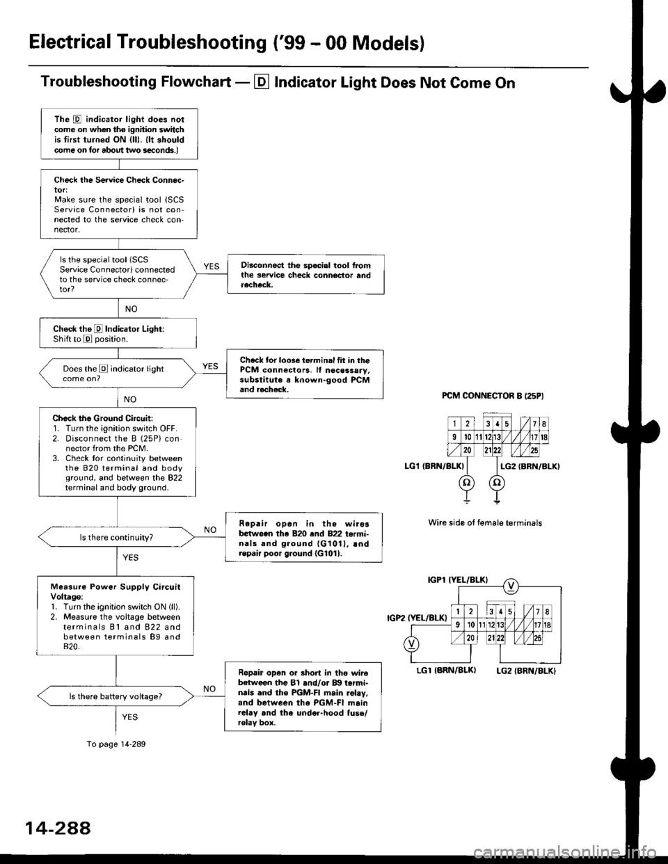
Electrical Troubleshooting ('99 - 00 Models)
Troubleshooting Flowchart - El Indicator Light Does Not Come On
PCM CONNECTOR B I25PI
LGl {BRN/BLK)
Wire side ot female terminals
LGlIARN/BLK) LG2IBRN/BLKI
The D indicator light does notcome on whon ths ignhion switchis tirst turned ON {lll. llt shouldcome on tor about two s€conds.)
Check the Service Check Connec-tor:Make sure the special tool {SCSService Connectorl is not connected to the service check con-nector,
ls the special tool (SCS
Service Connectorl connectedto the service check connec-tor?
Disconnect the sp€cial tool f]omthe seruice chcck connoclor andaecheck.
Check the E Indicalor Light:Shift to E posjtion.
Check tor loose te.minal fit in thePCM connectors, lf nocessary,substitute a known-good PCMand aecheck.
Does the E indicator light
Check the Ground Circuit:1. Turn the ignition switch OFF.2. Disconnect the B (25P) connector from the PCM.3. Check tor continuity betweenthe 820 terminal and bodyground, and between the 822terminal and body ground.
Fepair open in th. wirosb€tw.en the 820 end 822 termi-nals and ground {G1011, !ndrepair poor ground {G1011.
ls there continuity?
Measure Power Supply CircuitVoltage:1. Turn the ignitlon switch ON (ll).
2. Measure the voltage betweenterminals Bl and 822 andbetween terminals B9 and820.
Ropair op€n or short in tho wireb€tween the Bl and/or B!| tarmi-nds and the PGM-FI main .ohy,and between tho PGM-FI mainrelay and the under-hood fuso/r€lav box.
ls there battery voltage?
To page 14-289
14-2AA
Page 967 of 2189
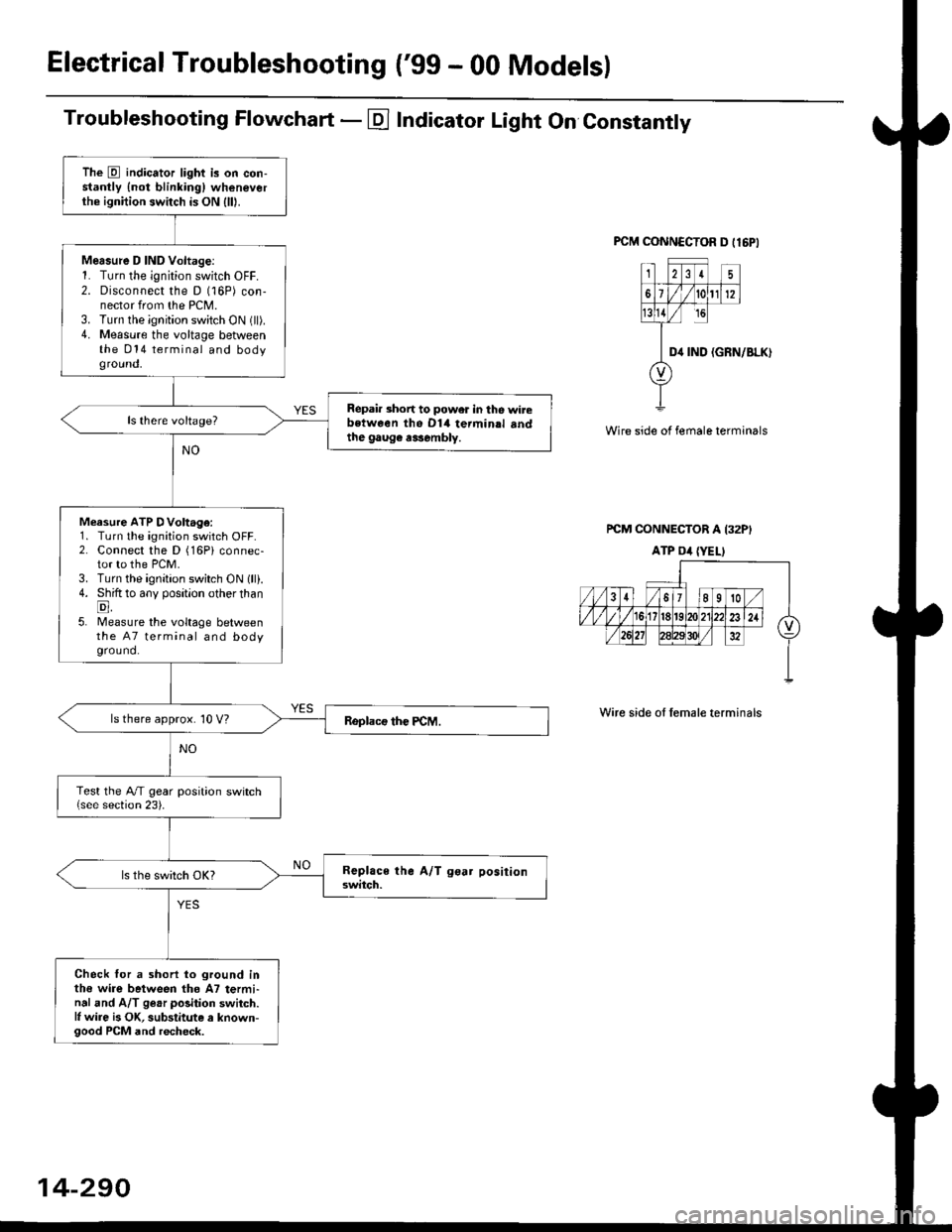
ElectricalTroubleshooting ('gg - 00 Models)
Troubleshooting Flowchart - E Indicator Light On Constantly
FCM CONNCCTOR D tl6PI
23I5
61t012
tsll / rc
II D4 rND
o
(GRN/BLK)
Wire side of female terminals
rcM CONNECTOR A I32PI
ATP Dil {YELI
Wire side of lemale terminals
The E indicator light is on con-stantly {not blinkingl wheneverthe ignition switch is ON lll|.
Mersure D IND Voltage:1. Turn the ignition switch OFF.2. Disconnect the D (16P) con-nector from the PCM.3. Turn the ignition switch ON (ll).4. Measure the voltage betweenthe 014 terminal and bodyground,
Repair short to power in tho wirebstween the Dl4 termin.l sndthe gaug€ r3sembly.
Measure ATP DVoltage:1. Turn the ignition switch OFF.2. Connect the D (16Pi connec-tor to the PCM.3. Turn the ignition switch ON lll).4. Shift to any position other thanE,5. lMeasure the voltage betweenthe 47 terminal and bodyground.
ls there approx. 10 V?
Test the A/T gear position switch{see section 23).
Check for a shorl lo ground inthe wire between tho A7 termi-nal and A/T ge.r polition switch.l, wire is OK, substitute a known-good PCM and recheck.
14-290
Page 1057 of 2189
l.
t
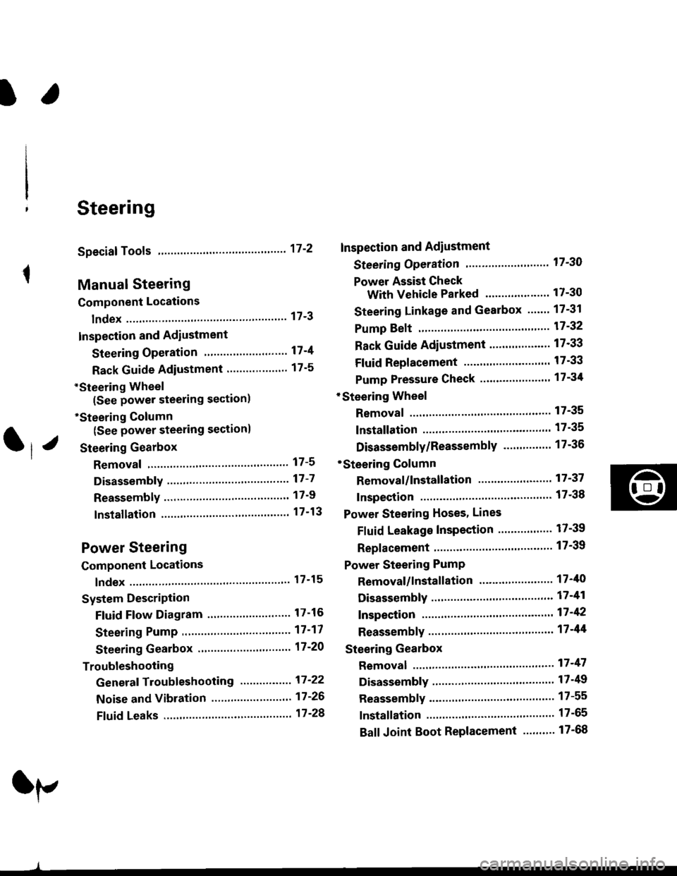
Steering
Speciaf Tools ....."'.....17-2
Manual Steering
Component Locations
lndex ................ ....... 17-3
Inspection and Adiustment
Steering Operation "'......"............... 17-4
Rack Guide Adiustment ................... 17-5
*Steering Wheel
(See power steering section)
*Steering Column
(See power steering sectionl
Steering Gearbox
Removal ................. 17-5
Disassembly ......."" 17-7
ReassemblY ..'......... 17-9
lnstallation ............. 17-13
Power Steering
Component Locations
lndex "......."..... """' 17-15
System DescriPtion
Fluid Flow Diagram .........""............. 17'16
Steering Pump ............'... "........"'...-- 17 -17
Steering Gearbox .".................'...'.'.' 17-20
Troubleshooting
Generaf Troubleshooting ..........--.... 17'22
Noise and Vibration ......................... 17 -26
Ffuid Leaks .............17-28
Inspection and Adiustment
Steering Operation'......."'........'...... 1 7-30
Power Assist Check
With Vehicle Parked .."................ 17-30
Steering Linkage and Gearbox ....." 17-31
Pump Beft ...--.""".. 17-32
Rack Guide Adiustment .'.......'.......'. 17'33
Fluid Replacement .....'.."................. 17-33
Pump Pressure Check .............'....-. " 17 -34
'Steering Wheel
Removal .."'........'... 17-35
lnstallation ............. 17-35
Disassembly/Reassembly ......'.....'.' 17-36
*Steering Column
Removal/lnstallation ....'........... ---.... 17'37
lnspection .............. 17'38
Power Steering Hoses, Lines
Fluid Leakage Inspeetion ............'.... 17-39
Replacement ......".. 17-39
Power Steering PumP
Removal/lnstallation .'.'..'..'............. 17-40
Disassembly ".........17-41
fnspection .......---'." 17'42
Reassembly ..'.........17-44
Steering Gearbox
Removal ....'........."' 17'47
DisassemblY ..........' 17-49
Reassembly '........... 17-55
lnstallation ............. 17-65
Ball Joint Boot Replacement .......'.. 17-68
Ir/
lp
Page 1071 of 2189
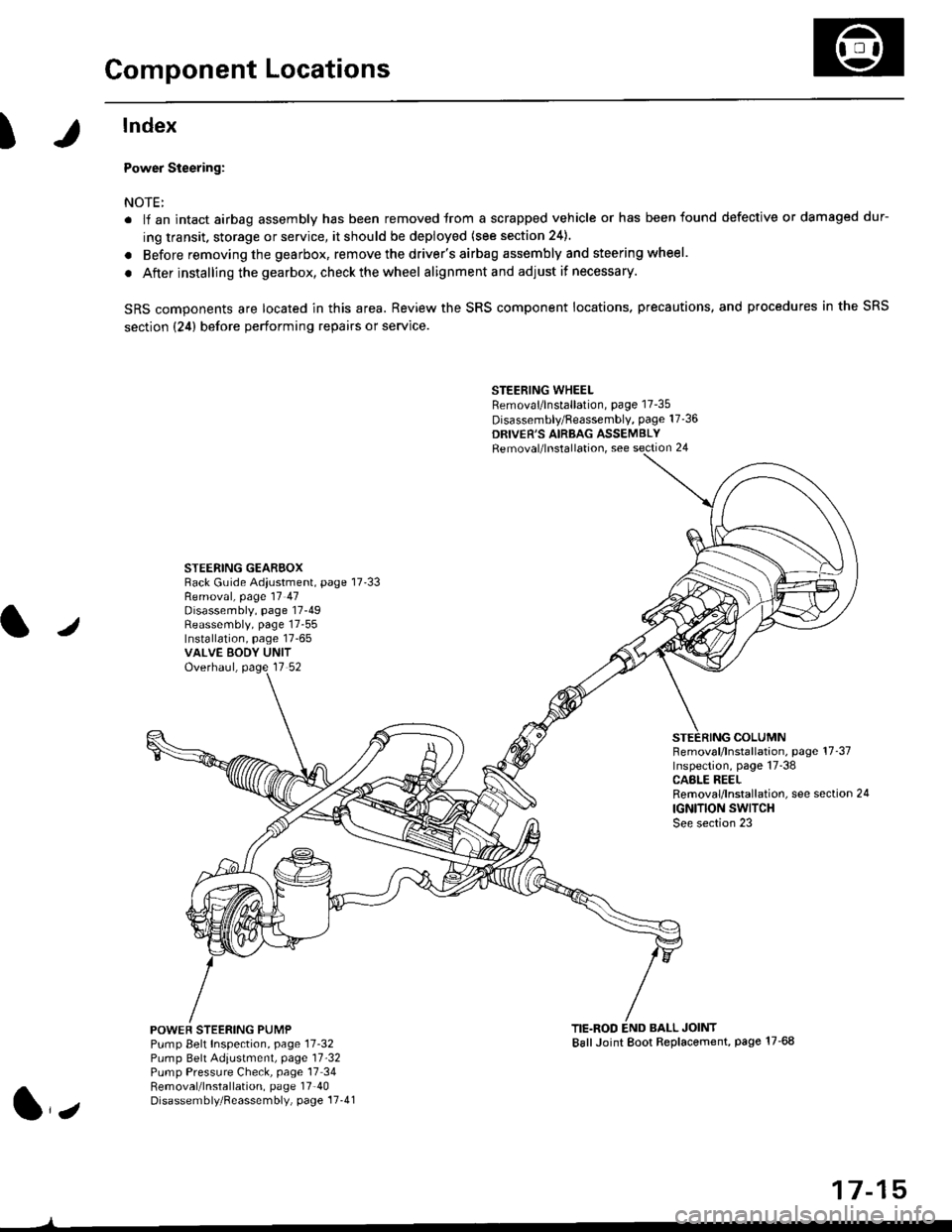
Component Locations
I
lndex
Power Steering:
NOTE:
. li an intact airbag assembly has been removed trom a scrapped vehicle or has been found defective or damaged dur-
ing transit. storage or service, it should be deployed (see section 24).
. Before removing the gearbox, remove the driver's airbag assembly and steering wheel.
. After installing the gearbox, checkthewheel alignmentand adjust if necessary.
SRS components are located in this area. Review the SRS component locations. precautions, and procedures in the SRS
section {24} before performing repairs or service.
STEERING WHEELRemoval/lnstallation, page 17-35
Disassembly/Feassembly, page 17-36
DRIVER'S AIRBAG ASSEMBLYRemoval/lnstallation, see section 24
STEERING GEAREOXRack Guide Adiustment, page 17'33
/
Removal, page 17 47Disassembly, page 17-49Reassembly, page 17-55Installation, page 17-65VALVE EODY UNITOverhaul, page 17 52
COLUMNFemoval/lnstallation, page 17-37Inspection, page 17-38CASLE REELRemoval/lnstallation, see section 24
IGNITION SWITCHSee section 23
POWEF STEERING PUMPPump Belt Inspection, page 11-32Pump Belt Adiustmenl, page 11'32Pump Pressure Check, page 17 34Removal/lnstallation, page 17'40Disassembly/Reassembly, page 17-41
TIE.ROD END BALL JOINTBallJoint Boot Replacement, page 17-68
1,,
17-15
Page 1072 of 2189
System Description
Fluid Flow Diagram
The system is a compact rotary-valve-type power steering, connected to the steering gearbox. The fluid pressure is pro-
vided by a vane-type pump which is driven by the engine crank pulley. The amount of fluid and pressure is regulated by
the flow control valve built into the pump. The fluid pressure from the pump is delivered to the valve body unit around the
pinion of the steering gearbox. The valve inside the valve body unit controls the hydraulic pressure and changes the direc-
tion of the flow. The fluid then flows to the power cylinder. where rack thrust is generated. Fluid returning from the power
cylinder flows back to the reservoir, where the fluid is "filtered" and supplied to the pump again.
RESERVOIR
VALVE BOOY UNIT
SUB.VALVE
FLOW CONTROL VALVESTEERING GEARBOX
17-16
Page 1076 of 2189
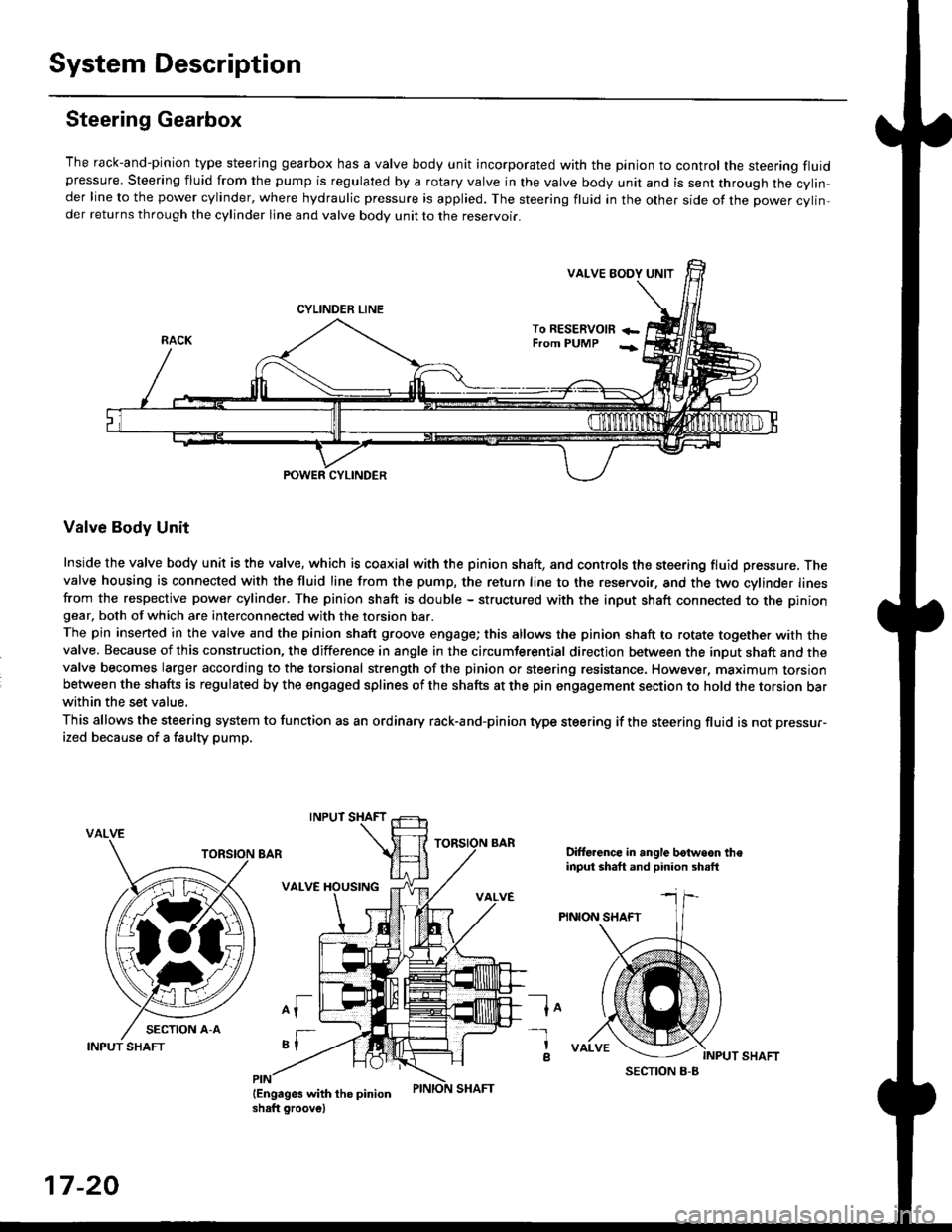
System Description
Steering Gearbox
The rack-and-pinion type steering gearbox has a valve body unit incorporated with the pinion to control the steering fluidpressure. Steering fluid from the pump is regulated by a rotary valve in the valve body unit and is sent through the cylin,der line to the power cylinder, where hydraulic pressure is applied. The steering fluid in the other side of the power cylin,der returns through the cylinder line and valve body unit to the reservoii.
VALVE EODY UNIT
CYLINDER LINE
To RESERVOm +-From PUMP -;
POWER CYLINDER
Valve Body Unit
Inside the valve body unit is the valve, which is coaxial with the pinion shaft, and controls the steering fluid pressure. Thevalve housing is connected with the fluid line from the pump, the return line to the reservoir, and the two cylinder linesfrom the respective power cylinder. The pinion shaft is double - structured with the input shaft connected to the piniongear, both of which are interconnected with the torsion bar.
The pin inserted in the valve and the pinion shaft groove engage; this allows the pinion shaft to rotate together with thevalve. Because of this construction, the difference in angle in the circumferential direction between the input shaft and thevalve becomes larger according to the torsional strength of the pinion or steering resistance. However, maximum torsionbetween the shafts is regulated by the engaged splines of the shafts at the pin engagement section to hold the torsion barwithin the set value,
This allows the steering system to function as an ordinary rack-and-pinion type steering if the steering fluid is not pressur-
ized because of a faulty pump,
VALVE
Difforence in angle botwoon theinput shaft and pinion shsft
PINION SHAFT
lo
INPUT SHAFT
-l
a
17-20
INPUT SHAFT