Page 1416 of 2189

Heater Control Panel
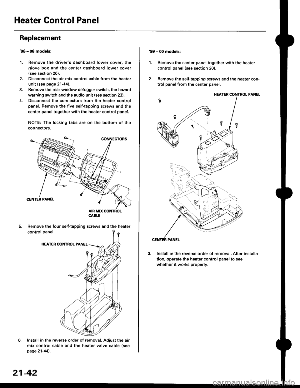
'95 - 98 modolsi
Remove the driver's dashboard lower cover, the
glove box and the center dashboard lower cover(see section 20).
Disconnect the air mix control cabls from the heater
unit {see page 21-44).
Remove the rear window defogger switch, the hazard
warning switch and the audio unit (see section 23).
Disconnect the connectors from the heater control
panel. Remove the five self-tapping screws and the
center panel together with the heater control panel.
NOTE: The locking tabs are on the bottom of the
connecrors.
Install in the .everse order of removal. Adjust the air
mix control cable and the heater valve cable {seepage 21-44)..
Replacement
1.
Remove the four self-tapping screws and the heater
21-42
1.
'9!, - 00 modols:
Remove the center panel together with the heater
control panel (see section 20).
Remove the self-tapping screws and the heater con-
trol panelfrom the center Danel.
Install in the reverse order of removal. After
tion, operate the heater control panel to see
whether it works properly.
installa-
Page 1418 of 2189

Temperature Control
Adjustment -'96 - 98 Models
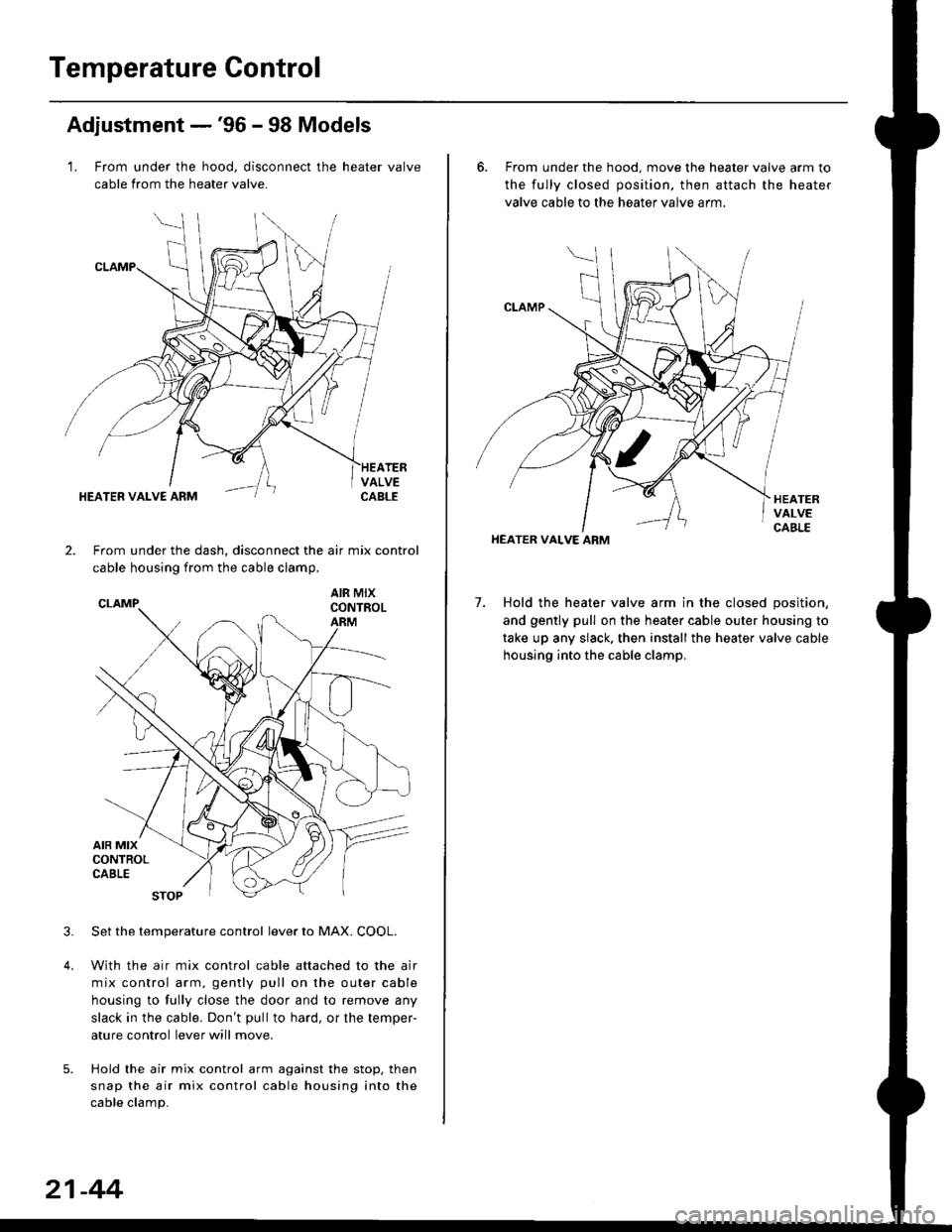
1. From under the hood, disconnect the heater valve
cable from the heater valve.
TERVALVECABLEHEATER VALVE ARM
2.From under the dash, disconnect the air mix control
cable housing from the cable clamp,
AIR MIXCONTROLARM
3.Set the temperature control lever to MAX. COOL.
With the air mix control cable attached to the air
mix control arm, gently pull on the outer cable
housing to fully close the door and to remove any
slack in the cable. Don't pullto hard, or the temper-
ature control lever will move.
Hold the air mix control arm against the stop. then
snap the air mix control cable housing into the
cable clamp.
21-44
6. From under the hood. move the heater valve arm to
the fully closed position. then attach the heater
valve cable to the heater valve arm.
7. Hold the heater valve arm in the closed position,
and gently pull on the heater cable outer housing to
take up any slack. then install the heater valve cable
housing into the cable clamp.
HEATER VALVE ARM
Page 1419 of 2189
Adjustment -'99 - 00 Models
1. From under the hood, open the cable clamp, then
disconnect the heater valve cable from the heater
valve arm.
From under the dash. disconnect the heater valve
cable housing from the cable clamp, and disconnect
the heater valve cable from the air mix control arm.
HEATER VALVE CABLE
Set the temperature control dial on MAX COOL with
the ignition switch ON {ll).
Attach the heater valve cable to the air mix control
arm as shown above. Hold the end of the heater
valve cable housing against the stop, then snap the
heater valve cable housing into the cable clamp.
HEATER VALVE ARM
5. From under the hood. turn the heater valve arm to
the fullv closed oosition as shown, and hold it,
Attach the heater valve cable to the heater valve
arm, and gently pull on the heater valve cable hous-
ing to take up any slack, then install the heater valve
cable housing into the cable clamp.
HEATER VALVE ARM
21-45
Page 1430 of 2189
Circuit Diagram
UNDER DASHFUSE/RELAY 8OX
N0.17 (7.54)
'96 - 98 Models
UNDER.HOOD FUSEi BELAY BOX
WHT/SLU BLKYEL
BLK
+
G751
3
'o
I8LK
I
G40lG402
GNITON SWITCH
N0.41 (8rA) N0.42 (40A)
COMPBESSORCLUTCHBELAY
BLUMHT
,l
(E) i,T'
BLUi BED
A/c ITHERMOSTAI BLU/REO
CONDENSEFFAN MOTOR
*F,.X,
FAN rl
BLK
{
G401G402
HEATERswrlcH
32
22-6
Page 1431 of 2189
'99 - 00 Models
UNDER DASHFUSE/BELAY BOX
No.l7 (7.54)
BLK
I
G751
$*"
O :8P coNNEcToF
n :20P CONNECToF
E 12P coNNEcroRBLK
d-
G401G402
UNDER HOOD FUSE/RELAY 8OX
N0.41 (P,0A) N0.42 (404)
COMPRESSORCLUTCHFELAY
GNITON SWTCH
HEATER CONTROL PANEL
22-7
Page 1432 of 2189
Troubleshooting
Symptom Chart
NOTE:
. Any abnormality must be corrected before continuing the test.. Because of the precise measurements needed. use a multimeter when testinq.. Before performing any troubleshooting procedures check:- Fuses No. 47 l7 -5 Al, No. 56 (20 A) in the under-hood fuse/relay box, and No. 17 (7.5 A) in the under_dash fuse/relavbox- Grounds No. c401, c402, G751- Cleanliness and tightness of alt connectors
SymptomRemedy
Condenser fan does not run at all.Perform the procedures in the flowchart {see page 22-9).
Compressor clutch does not engage.Perform the procedures in the flowchart lsee page 22-12).
Ay'C system does not come on (compressor and fan),Perform the procedures in the flowchan (see page 22-17).
Both heater and A,/C do not work.. '96 - 98 models-Perform the procedures in the flowchart
{see page 21-18).. '99 - 00 models-Perform the procedures in the flowchart(see page 21-35).
22-8
Page 1433 of 2189
Condenser Fan
CONDENSER FAN RELAY 4P SOCKET
JUMPERwlRE
(cont'd)
22-9
Conden3er fan does not run at all.
Check the No. 56 (20 A) fuse in the
unde.hood frJse/relaY box, and the
No. 17 (7.5 A) fuse in the under-
dash fuse/relay box.
Reolace the fuse{s), and techeck
Remove the condenser lan rclaY'
and test it (see page 22 21i
Replace the condensei fan relav.
Check the under-hood tus6/relaY
Measure the vohage between the
No. 2 terminalofthe condenser fan
relav 4P socket and bodv ground.
ls there battery voltage?
Check the condenser lan Powersupply circuit:Connect the No. 1 and No. 2 teF
minals of the condenser fan relay
4P socket with a jumper wire
Does the condenser fan run?To page 22-10
Io page 22 11
Page 1436 of 2189
Troubleshooting
Compressor
COMPRESSOR CLUTCH RELAY.P SOCKET
JUMPERWIRE
check the No. 56 (20 A) fuse in theunder'hood fuse/relay box, and theNo. 17 (7.5 A) fuse in the under,dash fuse/relay box.
Replace the fussls), and .echeck.
Remove the compressor clutchrelay, and test it {see page 22 21).
Check th6 und€r-hood tu3e/reby
Measure the voltage between theNo. 2 terminal of the compressorclutch relay 4P socket and bodyground.
Check the compressor clutchpow€r supply circuit:Connect the No. 1 and No. 2 termi-nals of the compressor clutch relay4P socket with a jumper wire.
Does the compressor clutch click?fo page 22-13
To page 22 14
22-12