Page 567 of 2189
J
Transaxle
cf utch .""""" 12'1
Manual Transmission ............"'.'..".'...'. 13-1
Automatic Transmission ........ "........ " ". 1 4-1
Differential ... 15-1
Driveshafts ." 16-1
Page 570 of 2189
lllustrated Index
\
NOTE:
. Whenever the transmission is removed, clean and grease the release bearing sliding surface
. lf the parts marked with an asterisk (*) are removed, the clutch hydraulic system mustbe bled (seepage 12-6)
. Inspect the hoses for damage, leaks, interference, and twisting
'RESERVOIF TANK
ASSIST SPRING
LOCK PIN
5x1,0mm9.8 N.m (1.0 kgf.m,7.2 tbtftl*CLUTCH LINE15 N.m {1.5 kgJ m,11 tbt.ft)
RELEASE BEARINGRemoval/lnspection, page 12-1 1Installation, page 12-'12
*CLUTCH MASTER CYLINDERRemoval/lnstallation, page 12 5
6x1.0mm9.8 N.m (1.0 kgf.m,7.2 tbf.ft)
FLYWHEELInspectaon, page 12IReplacement, Page 12-9
CLUTCH DISCRemoval/lnspection, page 1 2-8
lnstallation, page 12-'10
'12 x 1.0 mm118 N.m {12.0 kgt'm,86.8lbfft)
PBESSURE PLATEBemoval/lnspection, page 12 7Installation, page 12''10
8 x 1.25 mm22 N m (2.2 kgf.m, 16lbf ft)
ISLAVE CYLINDERRemoval/lnstallation, page 12_6
12-3
Page 580 of 2189
J
Manual Transmission
S40 Model
(All except'99 - 00 2-door Si' SiR)
Manual Transmission ....."......'.'..".....". 13-1
S4C Model ('99 - 00 2-door Si, SiRl
Manual Transmission ...........................' 13-45
\
ta
Page 581 of 2189

\
S40 Model (All except'99 - 00 2-door Si' SiR)
Manual Transmission
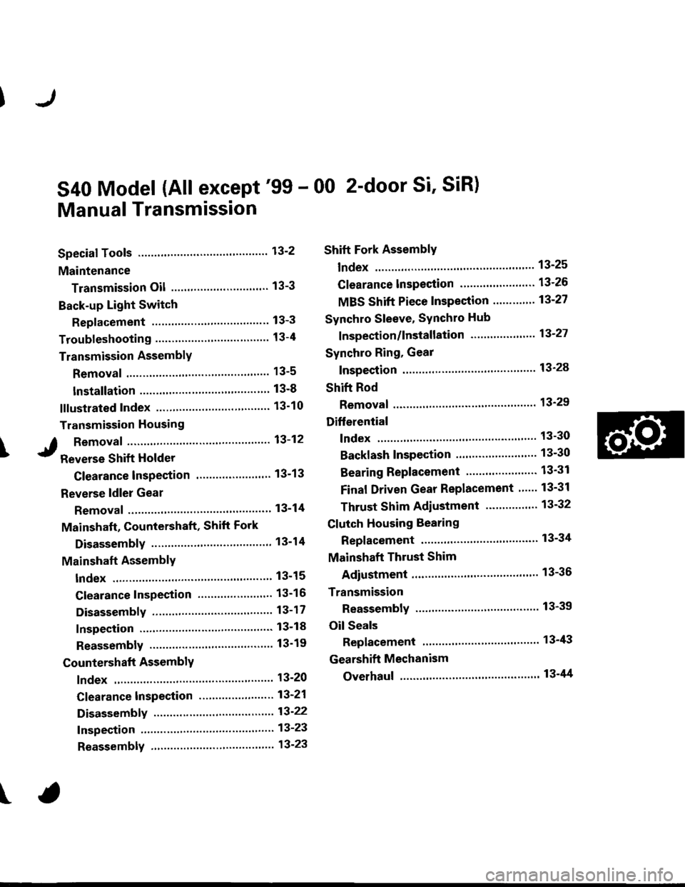
Special Tools ..'.......... 13-2
Maintenance
Transmission Oil .............................. 13-3
Back-up Light Switch
Replacement ......... 13-3
Troubleshooting '....... 13-4
Transmission AssemblY
Removal ................. 13-5
lnstallation ............. 13-8
lllustrated Index ...............'........."........ 13-10
Transmission Housing
I Removaf .."""""""' 13-12
J R"rr"r"" Shift Holder
Clearance lnspection ....................... 13-13
Reverse ldler Gear
Removal ....'.........." 13-14
Mainshaft, Countershaft, Shift Fork
Disassembly ......'... 13-14
Mainshaft AcsemblY
Index ............... ....... 13-15
Clearance Inspection ..'.................... 13-16
Disassembly .......... 13-17
Inspection ....'......... 13-18
Reassembly ........... 13-19
Countershaft AssemblY
lndex ................ ...... 13-20
Clearance lnspection ."..........'......." 13-21
Disassembly ..."""' 13-22
Inspection .............. 13-23
Reassembly ..'.""... 13-23
Shift Fork AssemblY
lndex ............... ."'... 13-25
Clearance lnspection ."......."........'.. 13'26
MBS Shift Piece Inspection ....-.....'.. 13'27
Synchro Sleeve, Synchro Hub
f nspection/lnstallation .......'...... ".... 13'27
Synchro Ring, Gear
Inspection '....'..".... 13'28
Shift Rod
Removal .'......".""" 13'29
Differential
lndex ......."'...... .'."' 13-30
Backlash Inspection ..........."......."... 13-30
Bearing Beplacement'.............'.".... 13'31
Final Driven Gear Replacement '..... 13-31
Thrust Shim Adiustment ..."........... 13-32
Clutch Housing Bearing
Replacement .......'. 13-34
Mainshaft Thrust Shim
Adiustment '....'..".. 13-36
Transmission
Reassembly ........... 13-39
Oil Seals
Replacement ......... 13-43
Gearshift Mechanism
Overhaul ................ 13-44
\
Page 583 of 2189

MaintenanceBack-up Light Switch
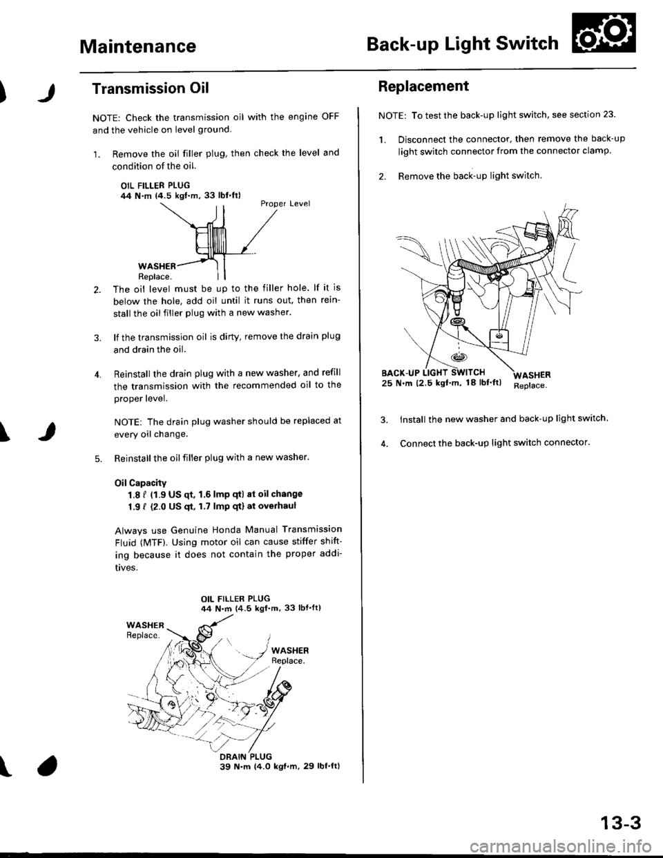
Transmission Oil
NOTE: Check the transmission oil with the engine OFF
and the vehicle on level ground.
1. Remove the oil filler plug, then check the level and
condition of the oil.
OIL FILLER PLUG/14 N.m (4.5 kgl.m,33 lbl.ft)Proper Level
4.
WASHERReplace.
The oil level must be up to the filler hole. lf it is
below the hole, add oil until it runs out. then rein-
stall the oil filler plug with a new washer.
lf the transmission oil is dirty, remove the drain plug
and drain the oil.
Reinstall the drain plug with a new washer, and refill
the transmission with the recommended oil to the
proper lever.
NOTE: The drain plug washer should be replaced at
every oil change.
Reinstall the oil filler plug with a new washer.
OilCapacity
1.8 f (1.9 US qt. 1.6 lmp qtl at oil change
1.9 { (2.0 US $, 1.7 lmp qt) at overhaul
Always use Genuine Honda Manual Transmission
Fluid {MTF). Using motor oil can cause stiffer shift-
ing because it does not contain the proper addi-
t|ves.
\
\
Replacement
NOTE: To test the back-up light switch, see section 23
1. Disconnect the connector, then remove the back-up
light swirch connector from the connector clamp.
2. Remove the back-up light switch.
25 N.m (2.5 kgf'm, 18lbf'ltl
Install the new washer and back-up light switch
Connect the back-up light switch connector.
ASHER
13-3
Page 585 of 2189

Transmission Assembly
I
Removal
@. Make sure iacks and safety stands are placed prop€dy,
and hoist brackets are atlach€d to correct position on
the enginc.
. Apply parking brake and block rear whosls so car will
nol roll olf stands and lall on you while working under
it.
CAUTION: Use fender covers to svoid damaging painted
surfaces.
1. Disconnect the negative {-) cable first, then the pos-
itive (+) cable from the battery'
Drain transmission oil {see page 13-3).
Remove the intake air tube. intake air duct and air
cleaner housing assembly (see section 5).
Disconnect the starter motor cables, transmission
ground wire and back-up light switch connector.
6x1.0 mm BACK-UP LIGHT
9.8 N.m (1.0 ksf.m, 7.2 lbI.ft) swlTcH CoNNECTOR
8x 1 .25 mm8.8 N.m {0.9 kgt.m,6.5 lbf.ftl
\
ARTER
5. Remove the wire harness clamps.
vssCONNECTOR
6. Disconnect the vehicle speed sensor (VSS) connec-
ror.
Remove the clutch line bracket, clutch line clamp,
and slave cvlinder.
CAUTION:
. Do not opsr.te tho clutdh pedal once the 3lavc
cylindor has b6on romoved.
. Tske care not to bend tha clutch lin6.
7.
(cont'd)
13-5
Page 586 of 2189

Transmission Assembly
Removal (cont'dl
8. Remove the driveshafts (see section 161.
NOTE: Coat all the precision finished surfaces with
clean engine oil or grease. Tie plastic bags over the
driveshaft ends,
DRIVESHAFT
10 x 1.25 mrn43 N.m 14.4 kgt.m,32 rbf.frl
COTTER PINReplace. SELF12 x 1.25 mm49-59 N.m (5.0 -6.0 kgt.m,36-43 lbf.ft)
9. Remove exhaust pipe A.
Replace.12 x 1.25 mm64 N.m {6.5 kgt.m,47 lbf.tr)
GASKETSReplace.
IF\sELF-LocKtNG NUT.''1/Replace.8 x 1.25 mm16 N.m {1.6 kgf'm,12 tbf.ft)
EXHAUSTPIPE A
SELF-LOCKING NUTReplace.I x 1.25 mm22 N.m (2.2 kgf.m,16 tbt'fr)
SELF-LOCKING NUTReplace.D16Y5, D16Y7 engines:
33 N.m {3.4 kgf.m,25 lbt.ft)D16YB engine:10 x 1.25 mm54 N.m 15.5 kgl'm,40 lbf.ttl
SET RING
13-6
v'10. Remove the shift rod and extension rod.
SI'IIFT BOD
8x22mmSPRING PINReplace.
EXTENSION ROD
PIN PUNCH, 8.O mm(Commercially available)f-
'1'1. Remove the engine stiffeners and clutch cover.
D16Y5, D16Y8 engines:
10 x 1.25 mm44 N.m (4.5 kgt.m,33 tbf.tr)
I x 1.25 mm24 N.m (2.4 kgf.m17 lbt.frl
COVER
8 x 1.25 mm24 N.m 12.4 kgf'tn,17 tbt.tr)
Page 587 of 2189
12.
D16Y7 engine:
ENGINESTIFFENER
10 X 1.25 mmIt4 N'm (4.5 kqf'm,33 lbf'ltl
Install the bolts in the cylinder head and attach a
chain hoist to the bolts, then lift the engine slightly
to unload the engine and transmission mounts.
CHAIN HOIST
13. Remove the sDlash shield,
\
8 x 1.25 mm24 N.m {2.4 kgl.m,
SPLASH SHIELD
14. Remove the right front mounvbracket.
'lO x 'l.25 mm44 N'm (4.5 kgl.m,33 rbf.frl
Replace.12 x 1.25 mm
64 N.m t6.5 kgf.m,47 lbf'ft)
Place a jack under the transmission.
Remove the transmission mount bracket and mount.16.
TRANSMISSIONMOUNTTRANSMISSIONBRACKET
(cont'd)
13-7