1999 HONDA CIVIC Stereo sound system
[x] Cancel search: Stereo sound systemPage 1471 of 2189

l'f .
Electrical
Special Toofs .,....................,23-2
Troubleshooting
Tips and Precautions ..............,.................... . 23-3
Five-step Troubleshooting .............. ......... . . 23-5
wire color codes ..........,23-5
Schematic Symbols ........,................... . . .. .... 23-6
Relay and Control Unit Locations
Engine Compartment ...,..................... ... .. . 23'7
Dashboard ......................23-8
Dashboard/Door ......... 23-12*Airbags ................. ....... Section 24
Air Conditioning ......... Section 21
Aftelnator ..........."""" """ 23-112
Anti-lock Brake System {ABS) Section 19*A/T Gear Position Indicator .....................,. .... ... 23-149
Automatic Transmission Svstem .... . ....... Section 14
Batterv ......... . . . ... ...... .......23-91
Blower controls .. . ... Section 2l
Charging System ....'...........23'112
Connector ldentilication and Wire Harness
Routing .................. ......23'13
Cruise Control ............,........23-240
Dash Lights Brightness Controller ............. ....... 23-180
Fan controfs "" 23'126
Fuel PumD ........ . ........ section 11
Fuses/Refay ...............,..,,.. 23'62
PGM-FI Control System ......................,....... Section 1 1
*Gauges
Circuit Diagram ....,.,.......23-131
Fuef Gauge ...........'.'.......23-142
Gauge/lndicator .. . .. 23-129
Ground Distribution .. . 23-75
Heatei controls .. . ..... Section 21*Horn................. ...............23-196
*tgnition Switch ....................23-89
lgnition System .......,.... 23-102
*lntegrated Control Unit ....................................... 23-156
fnterlock System ,........ . . , ,23-144
Lighting System . . . .. ......... 23-161
Lights, Exterior
Back-up Lights ..'............23'171
Brake Lights .................. 23'174
Daytime Bunning Lights (Canadal ............... 23'166
Front Parking Lights ......,................ .'. .......... 23-167
Front Turn Signal Lights .......... . . ............ ..,.23-167
Headtights ....".'....-... ..... 23'167
High Mount Brake Light ...................... ... .23'179
License Plate Lights ...... 23'176
Taitfights ................ .......23'171
lnterior Lights ..-.......,, . 23-142
Moonroof ..,.................,........ 23-235
Power Distribution ....... . . .23-61
Power Door Locks .......,,,. .23'251
Power Mirrors ,..............,.,...23'206
Power Relays ....... . ...... . . .. 23-86
Power Windows ............,,....23-220
Rear Window Defogger .......................... . . ... . . 23-2OO
Spark Plugs . ..... . ........ .....23-111
Slarting System ................23-93*stereo Sound Svstem ,................. ..... ... . ... ,.,.,,23'147'Supplemental Restraint System (SRS) ... . Section 24
Turn Signal/Hazard Flasher System .......'.'....-... 23-173
*Undel-dash Fuse/Relay Box ............,.................. 23-85
vehicfe soeed sensor (VSSI """" ""' 23-140+Wipers/Washers .........,.,.,...23-214
NOTE: Unless otherwise specified, references to auto-
matic transmission (Mf) in this section include the CVT.
Page 1657 of 2189
Stereo Sound System
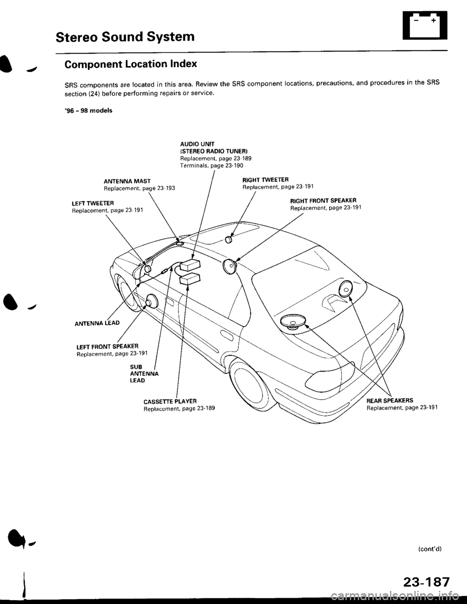
Component Location Index
SRS components are located in this area. Review the SRS component locations, precautions. and procedures in the SRS
section (24) before performing repairs or service.
'96 - 98 models
AUDIO UNIT(STEFEO RADIO TUNERIBeplacement, page 23 189Terminals, page 23-190
ANTENNA MASTReplacement, page 23 193
RIGHT TWEETERReplacement, Page 23 191
LEFT TWEETERReplacement, Page 23 191
ANTENNA LEAD
LEFT FRONT SPEAKER
Replacement, Page 23'191
SUB
RIGHT FRONT SPEAKERReplacement, page 23'191
ANTENNALEAD
CASSETTE PLAYER
Replacement, Page 23-189REAR SPEAKERSReplacement, page 23- 19'l
(cont'd)
23-147
q-
Page 1658 of 2189
Stereo Sound System
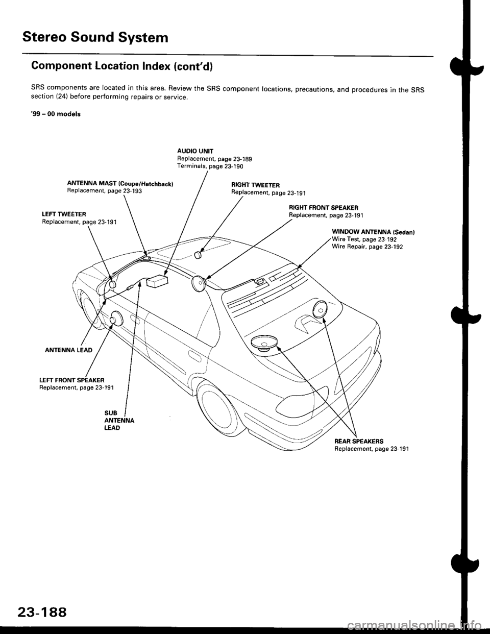
Component Location Index {cont'd)
SRS components are located ln this area. Review the SRS component locations, precautions, and orocedures in the sRSsection (24) before perlorming repairs or service.
'99 - 00 models
AUDIO UNITFeplacement, page 23-189Terminals, page 23-190
ANTENNA MAST (Coupe/Hatchbeck)Replacement, page 23,193RIGHT TWEETERReplacement, p6ge 23-191
LEFT TWEETERReplacement, page 23-191
ANTENNA LEAD
LEFT FRONTReplacement, page 23-191
RIGHT FRONT SPEAKERReplacernent, page 23-191
WINDOW ANTENNA {SedanlWire Test, page 23 192Wire Repair, page 23-192
SUB
I.TAO
REAR SPEAKERSReplacemont, page 23-191
23-1AA
Page 1660 of 2189
![HONDA CIVIC 1999 6.G Workshop Manual Stereo Sound System
UNDER-DASI.]FUSEi RELAY 8OX
l- -r,*;l
I
I
I
I
I
I
IYEUFED
(Sedan)--l
(Coupe/Horchbach)
Circuit Diagram (99 - 00 models)
No 30 (7.54)FUSE
V
IRED/BLK
I
I
I
vDASH LGHTSBHIGHTNESSCON HONDA CIVIC 1999 6.G Workshop Manual Stereo Sound System
UNDER-DASI.]FUSEi RELAY 8OX
l- -r,*;l
I
I
I
I
I
I
IYEUFED
(Sedan)--l
(Coupe/Horchbach)
Circuit Diagram (99 - 00 models)
No 30 (7.54)FUSE
V
IRED/BLK
I
I
I
vDASH LGHTSBHIGHTNESSCON](/manual-img/13/6068/w960_6068-1659.png)
Stereo Sound System
UNDER-DASI.]FUSEi RELAY 8OX
l- '-r,*;l
I
I
I
I
I
I
IYEUFED
(Sedan)--l
(Coupe/Horchbach)
Circuit Diagram ('99 - 00 models)
No 30 (7.54)FUSE
V
IRED/BLK
I
I
I
vDASH LGHTSBHIGHTNESSCONTROLLER
F;*";
,,,[.J:,a*[rrl
BLK
G501
/ _- | neolcn;diFnoNi | |DooR SPEAKEF | |
HlGHTTWEETER
UNDER.HOOD FUSE/RELAY BOX
RIGHT REAFSPEAKEBLEFT REARSPEAKEF
LEFTTWEETER
23-190
Page 1662 of 2189
Stereo Sound System
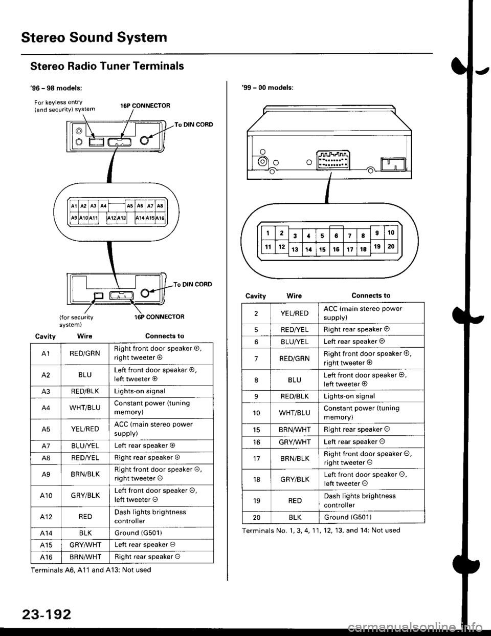
Stereo Radio Tuner Terminals
'96 - 98 models:
For keyless entry . t6p coNNEcroR(and securrty) syslem
To DIN CORD
To DIN CORD
(for securitysystem)
Cavity Wire
A1RED/GRNRight front door speaker o,
right tweeter @
BLULeft front door speaker @,
left tweeter @
A3RE D/B LKLights-on signal
A4WHT/BLUConstant power (tuning
memoryl
A5YEL/REDACC (main stereo power
suppry)
A7BLUI/ELLeft rear speaker O
A8RE DI/E LRight rear speaker O
A9BRN/BLKRight front door speaker O,
right tweeter o
A10GRY/BLKLeft tront door speaker O,
left tweeter O
412REDDash lights brightness
controller
A14BLKGround (G501)
415GRYMHTLeft rear speaker O
Al6BR N/VVHTRight rear speaker O
Terminals A6, A11 and A13: Not used
23-192
'99 - 00 models:
CsvityConnccts toWire
2YEL/REDACC (main stereo power
suppry)
5RE DI/E LRight rear speaker @
BLUI/ELLeft rear speaker @
7RED/GRNRight front door speaker @,
right tweeter @
8BLULeft front door speaker @,
left tweeter @
9RED/BLKLights-on signal
10WHT/BLUConstant power (tuning
memory)
15BRN,ryVHTRight rear speaker O
GRYMHTLeft rear speaker O
17BRN/BLKRight front door speaker O,
right tweeter O
18G RY/BLKLeft front door speaker O,
left tweeter O
'19REDDash lights brightness
controller
20BLKurouno t(l5u t,
Terminals No. 1, 3, 4, 11,12, 13, and 14: Not used
Page 1664 of 2189
Stereo Sound System
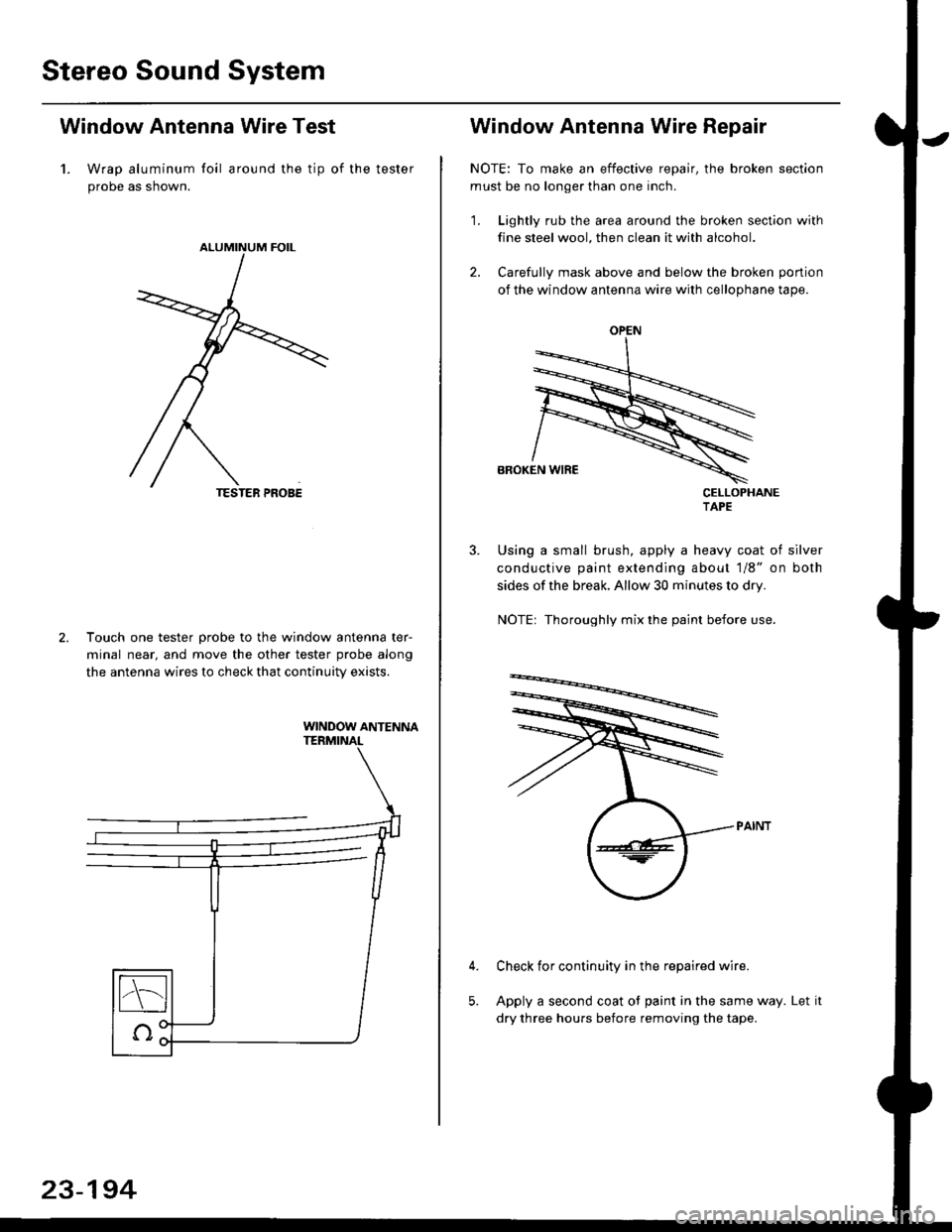
Window Antenna Wire Test
1. Wrap aluminum foil around the tip of the tester
probe as shown.
Touch one tester orobe to the window antenna ter-
minal near, and move the other tester probe along
the antenna wires to check that continuity exists.
WINDOW ANTENNA
23-194
OPEN
Window Antenna Wire Repair
NOTE: To make an effective repair, the broken section
must be no longer than one inch.
1. Lightly rub the area around the broken section with
fine steel wool, then clean it with alcohol.
2. Carefully mask above and below the broken portion
of the window antenna wire with cellophane tape.
CELLOPHANETAPE
Using a small brush, apply a heavy coat of silver
conductive paint extending about 1/8" on both
sides of the break, Allow 30 minutes to dry.
NOTE| Thoroughly mix the paint betore use.
Check for continuity in the repaired wire.
Apply a second coat of paint in the same way. Let it
dry three hours before removing the tape.
Page 2030 of 2189
Power Door Locks (cont'd)
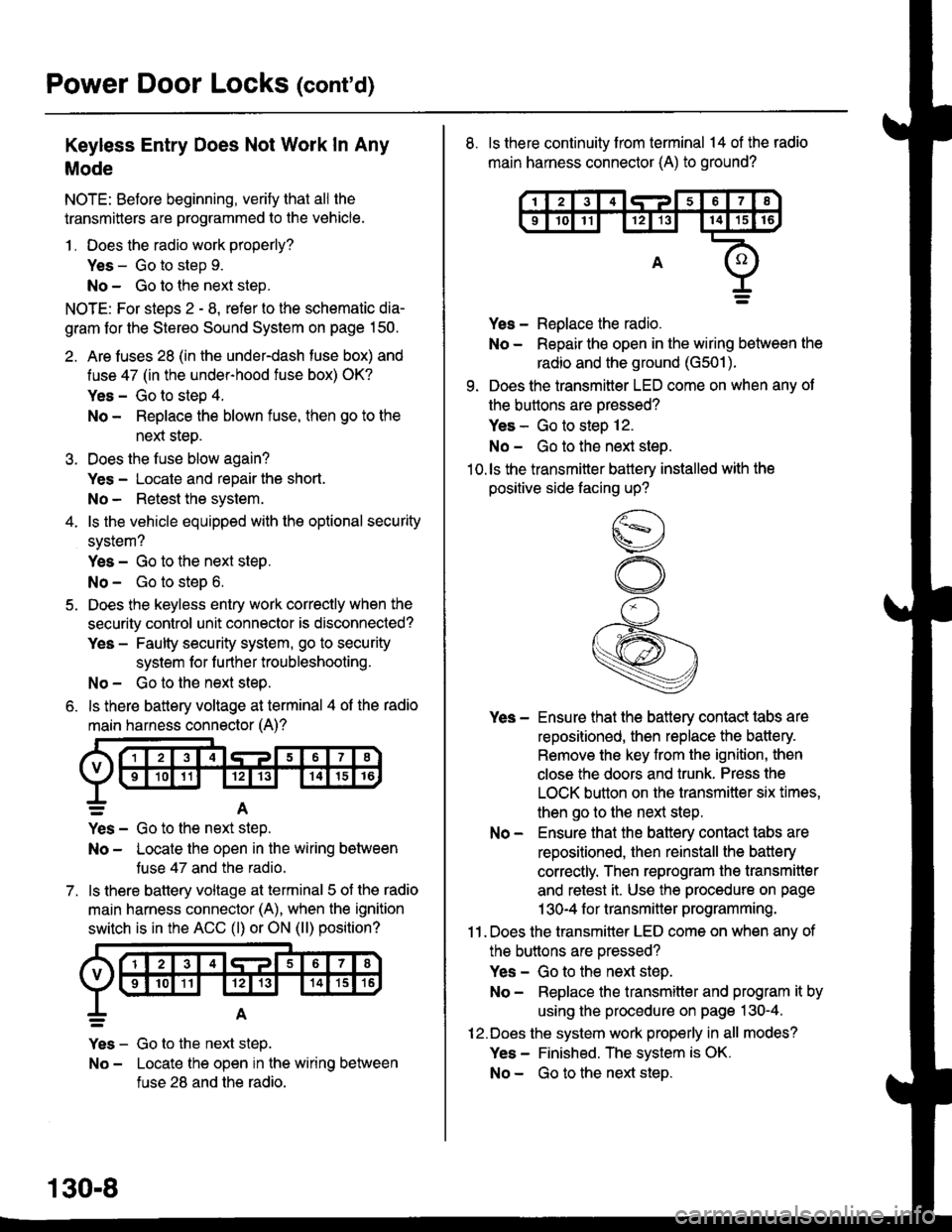
Keyless Entry Does Not Work In Any
Mode
NOTE: Before beginning, verify that all the
transmitters are programmed to the vehicle.
1 . Does the radio work properly?
Yes - Go to step 9.
No - Go to the neld step.
NOTE: For steos 2 - 8. refer to the schematic dia-
gram for the Stereo Sound System on page 150.
2. Are fuses 28 (in the under-dash fuse box) and
fuse 47 (in the under-hood fuse box) OK?
Yes - Go to step 4.
No - Replace the blown fuse, then go to the
nen steo.
3. Does the fuse blow again?
Yes - Locate and repair the short.
No- Retest the system.
4. ls the vehicle equipped with the optional security
system?
Yes - Go to the next steP.
No - Go to steD 6.
5. Does the keyless entry work correctly when the
security control unit connector is disconnected?
Yes - Faulty security system, go to security
system for f urther troubleshooting.
No - Go to the next step.
6. ls there battery voltage at terminal 4 of the radio
main harness connector (A)?
7.
=A
Yes - Go to the nen step.
No - Locate the open in the wiring between
tuse 47 and the radio.
ls there battery voltage at terminal 5 of the radio
main harness connector (A), when the ignition
switch is in the ACC (l) or ON (ll) position?
Yes - Go to the next step.
No - Locate the open in the wiring between
fuse 28 and the radio.
130-8
8. ls there continuity from terminal 14 of the radio
main harness connector (A) to ground?
Yes - Replace the radio.
No - Repair the open in the wiring between the
radio and the ground (G501).
9. Does the transmitter LED come on when any ot
the buttons are oressed?
Yes - Go to steo 12.
No - Go to the next steo.'10.ls the transmitter battery installed with the
positive side facing up?
Yes - Ensure that the battery contact tabs are
repositioned, then replace the battery.
Remove the key from the ignition, then
close the doors and trunk. Press the
LOCK button on the transmitter six times,
then go to the next step.
No - Ensure that the baftery contact tabs are
repositioned, then reinstall the batlery
correctly. Then reprogram the transmitter
and retest it. Use the procedure on page
1 30-4 f or transmitter programming.
11 . Does the transmitter LED come on when any of
the buttons are oressed?
Yes - Go to the next step.
No - Replace the transmitter and program it by
using the procedure on page 130-4.
12.Does the system work properly in all modes?
Yes - Finished. The system is OK.
No - Go to the next steD.
Page 2055 of 2189
How the Circuit Works
Arming the Security System
The security system can be armed:
r By pressing the remote control LOCK button
(if equipped)
. 20 seconds atter closing all doors (C)UDX only)
Arming with the Transmitter
The security system can be armed by removing the
ignition key from the ignition switch, closing all
doors and the trunk, and pressing the LOCK button
on the transmitter. When you arm the system in this
way, the remote control LED comes on, the status
LED flashes once per second, the parking lights
flash once. the doors lock. and the horn sounds
once if the beeo sound mode is on.
Passive Arming (CX and Dx only)
When you turn the ignition to OFF, remove the
ignition key from the ignition switch, and close all
the doors and the trunk; the system will
automatically arm itself 20 seconds after the trunk
or last door is closed. When you arm the system
this way, the status LED tlashes 4 times per second
during the exit delay time, and once per second
after the system is armed; the parking lights will
flash once to confirm that the system is armed.
Triggering the Alarm
Atter you've armed the system, it will trigger the
alarm if any door or the trunldhatch is opened. lf the
battery is disconnected when the system is armed or
in the alarm mode, reconnecting it will immediately
trigger the alarm. When the alarm is triggered, the
following will occur for 30 seconds:
. the horn sounds
o the parking lights flash once per second
. the status LED flashes hvice oer second
. the starter is disabled
After 30 seconds, the alarm will stop and the
system will rearm. Pressing the transmitter
UNLOCK button will disarm the svstem.
tlr
133-13
Disarming the System without the Remote
Transmitter (HX, LX, and EX)
You can disarm the system by turning the ignition
switch to ON (ll) and pressing the disarm/valet
switch on the right side ol the stereo tuner face. The
disarm switch will also disarm the svstem after the
system has been triggered.
Disarming the System with the Remote
Transmitter (Hx, Lx, Ex, DX-V, and Si)
Pressing the transmitter UNLOCK button will disarm
the system. The parking lights llash t\ivice if the
alarm has not been tnggered. The parking lights
flash three times if the alarm has been triggered.
The driver's door will unlock. lf you press the unlock
button twice, it will unlock all doors. lf a door is not
opened within 30 seconds, the system will lock all
doors and rearm.
Disarming the System (CX and DX only)
lf the system arms itself, there is a 20 second delay
after you open a door before the alarm will trigger.
To disarm the system in this mode, simply turn the
ignition switch to the ON position
ldentitying Tripped Sensors
The system identifies which sensor trips the alarm
by flashing the status LED. To display the trip
sensor flash code, press the disarm/valet switch 3
times within 5 seconds after the system has been
disarmed. The status sensor will blink according to
the followino codes:
SensorsNumber of Flashes
Door
TrunldHatch
System Switches
1 blink, pause, repeat
2 blinks, pause, repeat
3 blinks, pause, repeat
For further operating instructions, see the security
syslem owner's manual.
(cont'd)