Page 142 of 248
•After installing a snowplow to the vehicle, ensure the vehicle’s front
toe alignment and front ride height are within specification (reset if
required). These specifications are located in the vehicle’s Workshop
Manual. Adherence to the toe, tire pressures and ride height
specification is important for proper tire wear, ride, handling and
headlight aim. Also, maintain the engine oil and transmission fluid
change intervals following the severe duty schedule.
Do not exceed the GVWR or the GAWR specified on the
certification label.
Removing snowplow
Read the following instructions before removing a snowplow:
•After removing a snowplow from the vehicle, ensure the vehicle’s front
toe alignment and front ride height are within specification (reset if
required). These specifications are located in the vehicle’s Workshop
Manual. Adherence to the toe and ride height specification is
important for proper tire wear, ride, handling and headlight aim.
Snowplowing with your air bag equipped vehicle
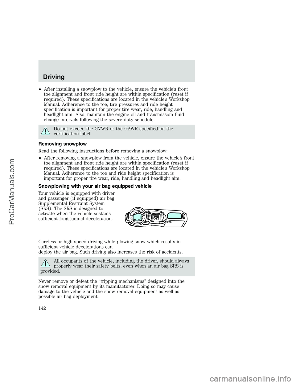
Your vehicle is equipped with driver
and passenger (if equipped) air bag
Supplemental Restraint System
(SRS). The SRS is designed to
activate when the vehicle sustains
sufficient longitudinal deceleration.
Careless or high speed driving while plowing snow which results in
sufficient vehicle decelerations can
deploy the air bag. Such driving also increases the risk of accidents.
All occupants of the vehicle, including the driver, should always
properly wear their safety belts, even when an air bag SRS is
provided.
Never remove or defeat the “tripping mechanisms” designed into the
snow removal equipment by its manufacturer. Doing so may cause
damage to the vehicle and the snow removal equipment as well as
possible air bag deployment.
Driving
142
ProCarManuals.com
Page 143 of 248
Do not attempt to service, repair, or modify the Air Bag
Supplemental Restraint System or its fuses. See your Ford or
Lincoln-Mercury dealer.
Engine temperature while plowing
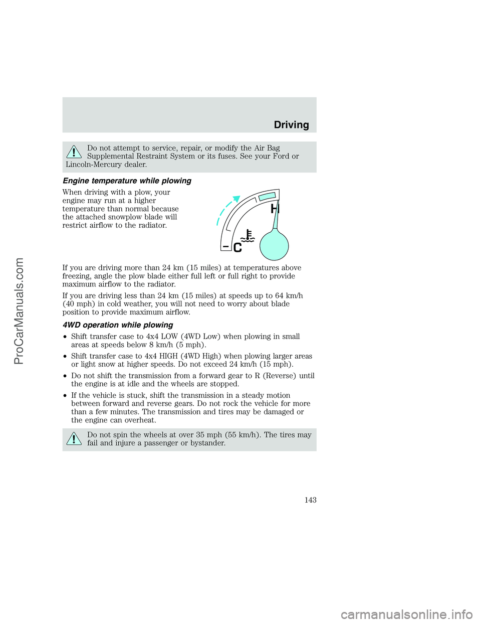
When driving with a plow, your
engine may run at a higher
temperature than normal because
the attached snowplow blade will
restrict airflow to the radiator.
If you are driving more than 24 km (15 miles) at temperatures above
freezing, angle the plow blade either full left or full right to provide
maximum airflow to the radiator.
If you are driving less than 24 km (15 miles) at speeds up to 64 km/h
(40 mph) in cold weather, you will not need to worry about blade
position to provide maximum airflow.
4WD operation while plowing
•Shift transfer case to 4x4 LOW (4WD Low) when plowing in small
areas at speeds below 8 km/h (5 mph).
•
Shift transfer case to 4x4 HIGH (4WD High) when plowing larger areas
or light snow at higher speeds. Do not exceed 24 km/h (15 mph).
•Do not shift the transmission from a forward gear to R (Reverse) until
the engine is at idle and the wheels are stopped.
•If the vehicle is stuck, shift the transmission in a steady motion
between forward and reverse gears. Do not rock the vehicle for more
than a few minutes. The transmission and tires may be damaged or
the engine can overheat.
Do not spin the wheels at over 35 mph (55 km/h). The tires may
fail and injure a passenger or bystander.
H
C
Driving
143
ProCarManuals.com
Page 144 of 248
HAZARD FLASHER
Use only in an emergency to warn traffic of vehicle breakdown,
approaching danger, etc. The hazard flashers can be operated when the
ignition is off.
•The hazard lights control is
located on top of the steering
column.
•Depress hazard lights control to
activate all hazard flashers
simultaneously.
•Depress control again to turn the
flashers off.
RESETTING THE FUEL PUMP SHUT-OFF SWITCH
After a collision, if the engine cranks but does not start, the fuel pump
shut-off switch may have been activated. The shut-off switch is a device
intended to stop the electric fuel pump when your vehicle has been
involved in a substantial jolt.
The fuel pump shut-off switch is
located in the passenger’s foot well,
behind the kick panel.
Roadside emergencies
144
ProCarManuals.com
Page 149 of 248

Fuse/Relay
LocationFuse Amp
RatingDescription
27 10A Ignition Run Power Feed (Customer
Access)
28 10A Brake Shift Interlock, DRL Relay Coil,
Speed Control Module, Backup Lamps,
Trailer Tow Backup Lamp Relay Coil,
Electronic Shift On The Fly Hub Lock
Solenoid
29 5A Instrument Cluster (Charge and Airbag
Warning Lamps)
30 30A PCM Relay Coil, Ignition Coil (Gasoline
only), Fuel Heater (Diesel only), Wastegate
Solenoid (Diesel only), Injector Driver
Module Relay Coil (Diesel only)
31 — Not Used
Relay 1 — Interior Lamp Relay
Relay 2 — Not Used
Relay 3 — Horn
Relay 4 — Power Window One Touch Down Relay
Relay 5 — Accessory Delay Relay
Power distribution box
The power distribution box, trailer tow and electronic shift on the fly
relay blocks are located in the engine compartment near the brake
master cylinder.
The power distribution box contains high-current fuses that protect your
vehicle’s main electrical systems from overloads.
Always disconnect the battery before servicing high current
fuses.
Always replace the cover to the Power Distribution Box before
reconnecting the battery or refilling fluid reservoirs.
If the battery has been disconnected and reconnected, refer to the
Batterysection of theMaintenance and Carechapter.
Roadside emergencies
149
ProCarManuals.com
Page 153 of 248
If your vehicle is equipped with 4WD, a spare tire of a different
size than the road tires should not be used. Such a tire could
result in damage to driveline components and make the vehicle
difficult to control.
Location of the spare tire and tools
The spare tire and tools for your vehicle are stowed in the following
locations:
Tool Location
Spare tire (pick-up
trucks only)Under the vehicle, just forward of the rear
bumper
Jack Regular cab, crew cab and SuperCab without
rear bench seat: Fastened to floor pan behind
rearmost seat on passenger side
SuperCab with rear bench seat: Under rear
bench on passenger side
Jack handle and lug
wrenchOn top of the radiator support at the front of
the engine compartment
Removing the spare tire (with spare tire carrier only)
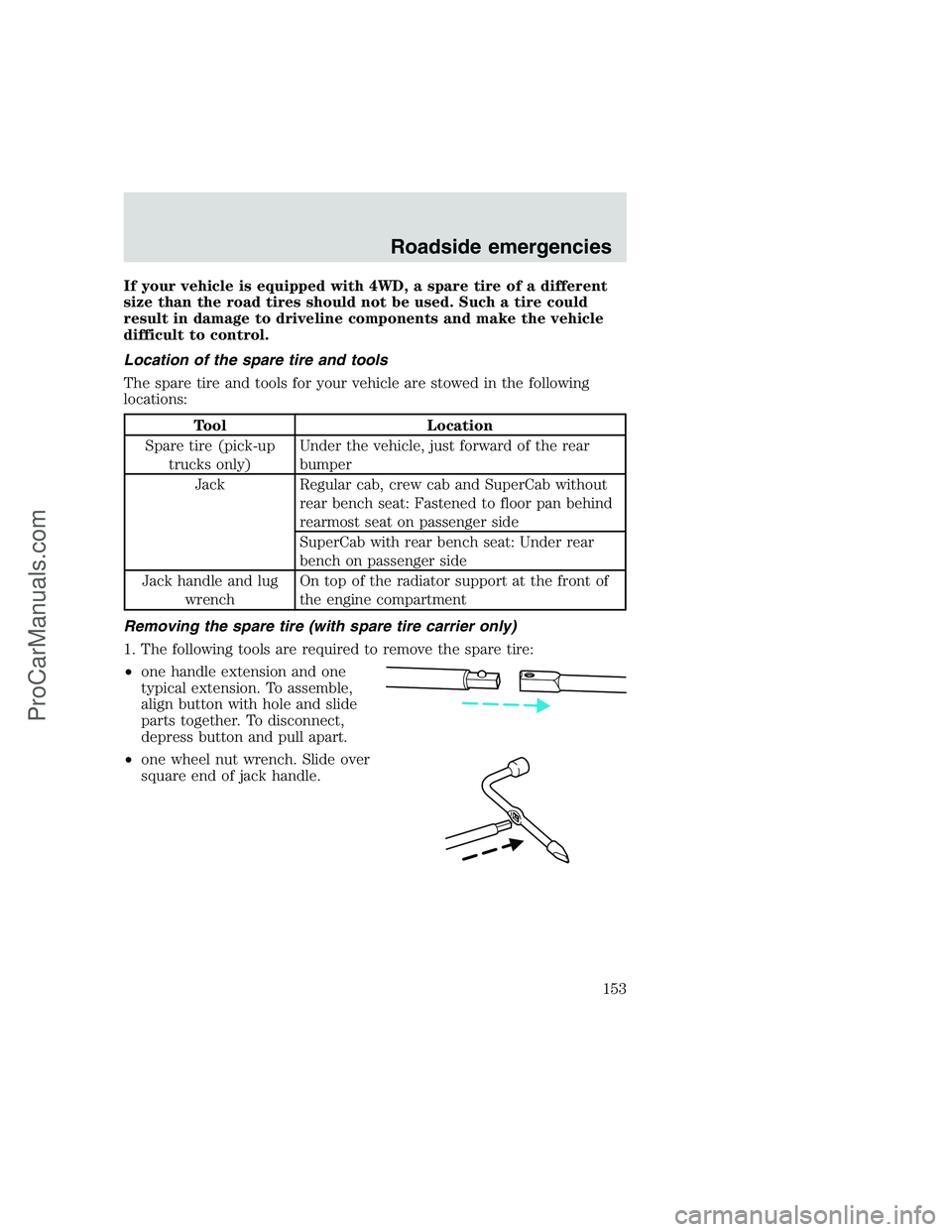
1. The following tools are required to remove the spare tire:
•one handle extension and one
typical extension. To assemble,
align button with hole and slide
parts together. To disconnect,
depress button and pull apart.
•one wheel nut wrench. Slide over
square end of jack handle.
Roadside emergencies
153
ProCarManuals.com
Page 155 of 248
5. The following steps are required to secure the support bracket (if
equipped) under the spare tire:
•Move the support bracket over the spare tire.
•Slide the support bracket over the eyebolt into the slot on the support
bracket.
•Tighten the eyebolt with tapered end of lug wrench leaving it
positioned at a right angle of the slot on the support bracket.
Tire change procedure
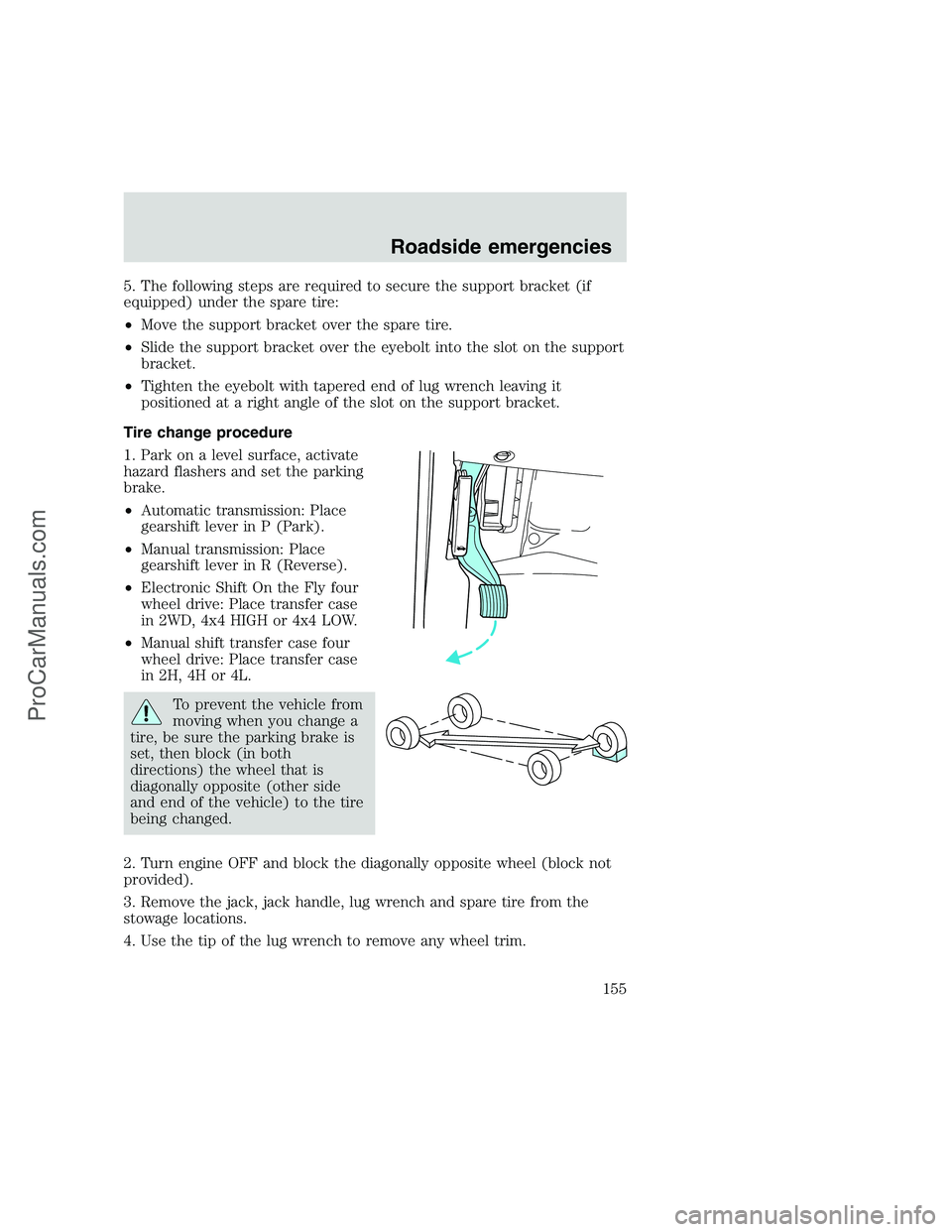
1. Park on a level surface, activate
hazard flashers and set the parking
brake.
•Automatic transmission: Place
gearshift lever in P (Park).
•Manual transmission: Place
gearshift lever in R (Reverse).
•Electronic Shift On the Fly four
wheel drive: Place transfer case
in 2WD, 4x4 HIGH or 4x4 LOW.
•Manual shift transfer case four
wheel drive: Place transfer case
in 2H, 4H or 4L.
To prevent the vehicle from
moving when you change a
tire, be sure the parking brake is
set, then block (in both
directions) the wheel that is
diagonally opposite (other side
and end of the vehicle) to the tire
being changed.
2. Turn engine OFF and block the diagonally opposite wheel (block not
provided).
3. Remove the jack, jack handle, lug wrench and spare tire from the
stowage locations.
4. Use the tip of the lug wrench to remove any wheel trim.
Roadside emergencies
155
ProCarManuals.com
Page 163 of 248
JUMP STARTING YOUR VEHICLE
The gases around the battery can explode if exposed to flames,
sparks, or lit cigarettes. An explosion could result in injury or
vehicle damage.
Do not push start your vehicle. You could damage the catalytic
converter.
Batteries contain sulfuric acid which can burn skin, eyes, and
clothing, if contacted.
Do not attempt to push start your vehicle. Automatic
transmissions do not have push-start capability.
Preparing your vehicle
1.Use only a 12–volt supply to start your vehicle.
2. Do not disconnect the battery of the disabled vehicle as this could
damage the vehicle’s electrical system.
3. Park the booster vehicle close to the hood of the disabled vehicle
making sure the two vehiclesdo nottouch. Set the parking brake on
both vehicles and stay clear of the engine cooling fan and other moving
parts.
4. Check all battery terminals and remove any excessive corrosion before
you attach the battery cables. Ensure that vent caps are tight and level.
5. Turn the heater fan on in both vehicles to protect any electrical
surges. Turn all other accessories off.
Roadside emergencies
163
ProCarManuals.com
Page 165 of 248
3. Connect the negative (-) cable to the negative (-) terminal of the
assisting battery.
4. Make the final connection of the negative (-) cable to an exposed
metal part of the stalled vehicle’s engine, away from the battery and the
carburetor/fuel injection system.
The preferred locations of an exposed metal part (togroundthe circuit)
are the alternator mounting brackets or an engine liftingeye.Do not
use fuel lines, engine rocker covers or the intake manifold asgrounding
points.
Do not connect the end of the second cable to the negative (-)
terminal of the battery to be jumped. A spark may cause an
explosion of the gases that surround the battery.
5. Be sure that the cables are clear of fan blades, belts and other moving
parts of both engines.
+–+–
+–+–
Roadside emergencies
165
ProCarManuals.com