Page 115 of 216

CONTROL-TRAC AUTOMATIC FOUR-WHEEL DRIVE SYSTEM
(IF EQUIPPED)
Your 4x4 features the heavy-duty Control-Trac system which includes a
computer-operated transfer case. This unique system is interactive with
the road, continually monitoring and adjusting torque delivery to the
front and rear wheels to optimize vehicle control.
Positions of the Control-Trac system
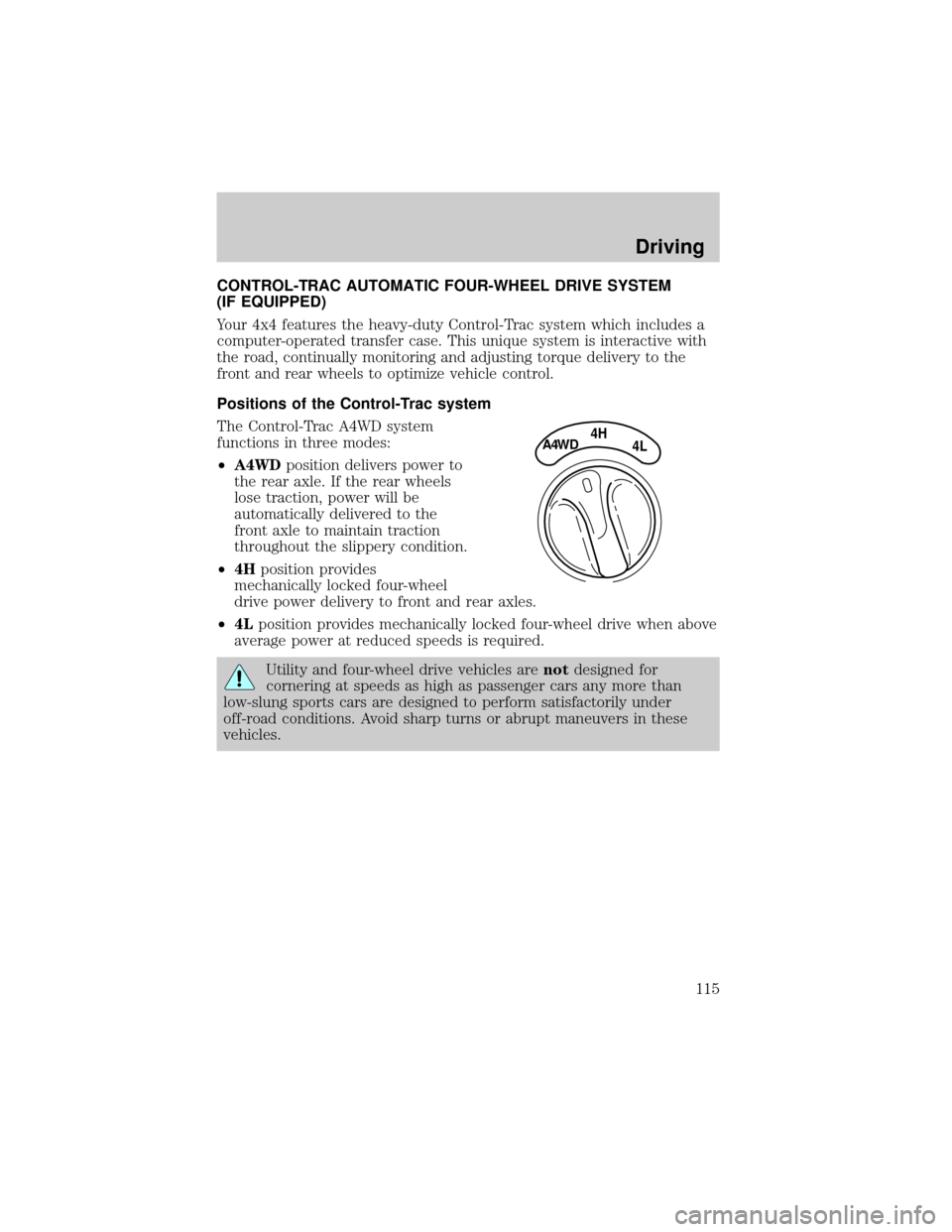
The Control-Trac A4WD system
functions in three modes:
²A4WDposition delivers power to
the rear axle. If the rear wheels
lose traction, power will be
automatically delivered to the
front axle to maintain traction
throughout the slippery condition.
²4Hposition provides
mechanically locked four-wheel
drive power delivery to front and rear axles.
²4Lposition provides mechanically locked four-wheel drive when above
average power at reduced speeds is required.
Utility and four-wheel drive vehicles arenotdesigned for
cornering at speeds as high as passenger cars any more than
low-slung sports cars are designed to perform satisfactorily under
off-road conditions. Avoid sharp turns or abrupt maneuvers in these
vehicles.
4HA4WD4L
Driving
115
Page 119 of 216

Driving on snow and ice
A 4WD vehicle has advantages over 2WD vehicles in snow and ice but
can skid like any other vehicle.
Avoid sudden applications of power and quick changes of direction on
snow and ice. Apply the accelerator slowly and steadily when starting
from a full stop.
When braking, apply the brakes as you normally would. In order to allow
the anti-lock brake system (ABS) to operate properly, keep steady
pressure on the brake pedal.
Allow more stopping distance and drive slower than usual. Consider
using one of the lower gears.
DRIVING THROUGH WATER
Do not drive quickly through standing water, especially if the depth is
unknown. Traction or brake capability may be limited and if the ignition
system gets wet, your engine may stall. Water may also enter your
engine's air intake and severely damage your engine.
If driving through deep or standing water is unavoidable, proceed very
slowly. Never drive through water that is higher than the bottom of the
hubs.
Once through the water, always try the brakes. Wet brakes do not stop
the vehicle as effectively as dry brakes. Drying can be improved by
moving your vehicle slowly while applying light pressure on the brake
pedal.
Driving through deep water where the transmission is submerged
may allow water into the transmission and cause internal
transmission damage.
VEHICLE LOADING
Before loading a vehicle, familiarize yourself with the following terms:
²Base Curb Weight: Weight of the vehicle including any standard
equipment, fluids, lubricants, etc. It does not include passengers or
aftermarket equipment.
²Payload: Combined maximum allowable weight of cargo, passengers
and optional equipment. The payload equals the gross vehicle weight
rating minus base curb weight.
Driving
119
Page 127 of 216

Launching or retrieving a boat
When backing down a ramp during boat launching or retrieval,
²Do not allow the static water level to rise above the bottom edge of
the rear bumper and
²Do not allow waves to break higher than 15 cm (six inches) above the
bottom edge of the rear bumper.
Exceeding these limits may allow water to enter critical vehicle
components, adversely affecting driveability, emissions, reliability and
causing internal transmission damage.
Replace the rear axle lubricant anytime the axle has been submerged in
water. Rear axle lubricant quantities are not to be checked or changed
unless a leak is suspected or repair required.
Disconnect the wiring to the trailer before backing the trailer into the
water. Reconnect the wiring to the trailer after the trailer is removed
from the water.
LUGGAGE RACK (IF EQUIPPED)
The rear crossbar can be adjusted to fit the item being carried. The front
crossbar does not move.
To adjust the luggage rack, push the
adjustment lever forward (toward
the front of the vehicle), then slide
the crossbar forward and lock the
adjusting levers by pushing them
down (toward the back of the
vehicle). Pull the crossbar rearward
to ensure that it is locked in place.
Load luggage at the front crossbar and adjust the rear crossbar as
necessary.
²Do not exceed 90.7 kg (200 lb) of luggage if the weight is placed
directly on the crossbars.
²Do not exceed 68 kg (150 lb) if the weight is resting directly on the
roof.
Use adjustable tie down loops to secure the load.
Driving
127
Page 131 of 216
The fuses are coded as follows.
Fuse/Relay
LocationFuse Amp
RatingDescription
1 25A Audio
2 5A Overhead Trip Computer, Electronic
Automatic Temperature Control (EATC),
Powertrain Control Module (PCM), Cluster
3 20A Cigar Lighter, OBD-II Scan Tool Connector
4 15A Autolamp Module, Remote Entry Module,
Mirrors, Air Suspension Switch
5 15A AC Clutch Relay, Speed Control Module,
Reverse Lamp, EVO Module, Climate Mode
Switch (Front Blower Relay), Daytime
Running Lamp Relay
6 5A Cluster, Overhead Trip Computer, Compass,
Brake Shift Interlock Solenoid, Air
Suspension Module, GEM Module, EVO
Steering Sensor
FUSE1 12 22
21323
617 27
718 28
819 29
930
20
31 21 11 10
RELAY
5 RELAY
4 RELAY
3 RELAY
2 RELAY
1
31424
41525
51626
Roadside emergencies
131
Page 132 of 216

Fuse/Relay
LocationFuse Amp
RatingDescription
7 5A Aux A/C Blower Relay, Console Blower
8 5A Radio, Remote Entry Module, GEM Module
9 Ð Not Used
10 Ð Not Used
11 30A Front Washer Pump Relay, Wiper Run/Park
Relay, Wiper Hi/LO Relay, Windshield Wiper
Motor, Rear Washer Pump Relay
12 Ð Not Used
13 20A Stop Lamp Switch (Lamps), Turn/Hazard
Flasher, Speed Control Module
14 15A Rear Wipers, Running Board Lamps,
Battery Saver Relay, Interior Lamp Relay,
Accessory Delay Relay (Power Windows)
15 5A Stop Lamp Switch, (Speed Control, Brake
Shift Interlock, ABS, PCM Module Inputs),
GEM Module
16 20A Headlamps (Hi Beams), Cluster (Hi Beam
Indicator)
17 10A Heated Mirrors, Heated Grid Switch
Indicator
18 5A Instrument Illumination (Dimmer Switch
Power)
19 Ð Not Used
20 5A Audio, Four Wheel Air Suspension (4WAS)
Module, GEM Module
21 15A Starter Relay, Fuse 20
22 10A Air Bag Module
23 10A Aux A/C, Heated Seats, Trailer Tow Battery
Charge, Turn/Hazard Flasher, Console
Blower Door Actuator
24 10A Climate Mode Switch (Blower Relay),
EATC (via fuse 7), EATC Blower Relay
25 5A 4 Wheel Anti-Lock Brake System (4WABS)
Module
Roadside emergencies
132
Page 134 of 216

If the battery has been disconnected and reconnected, refer to the
Batterysection of theMaintenance and Carechapter.
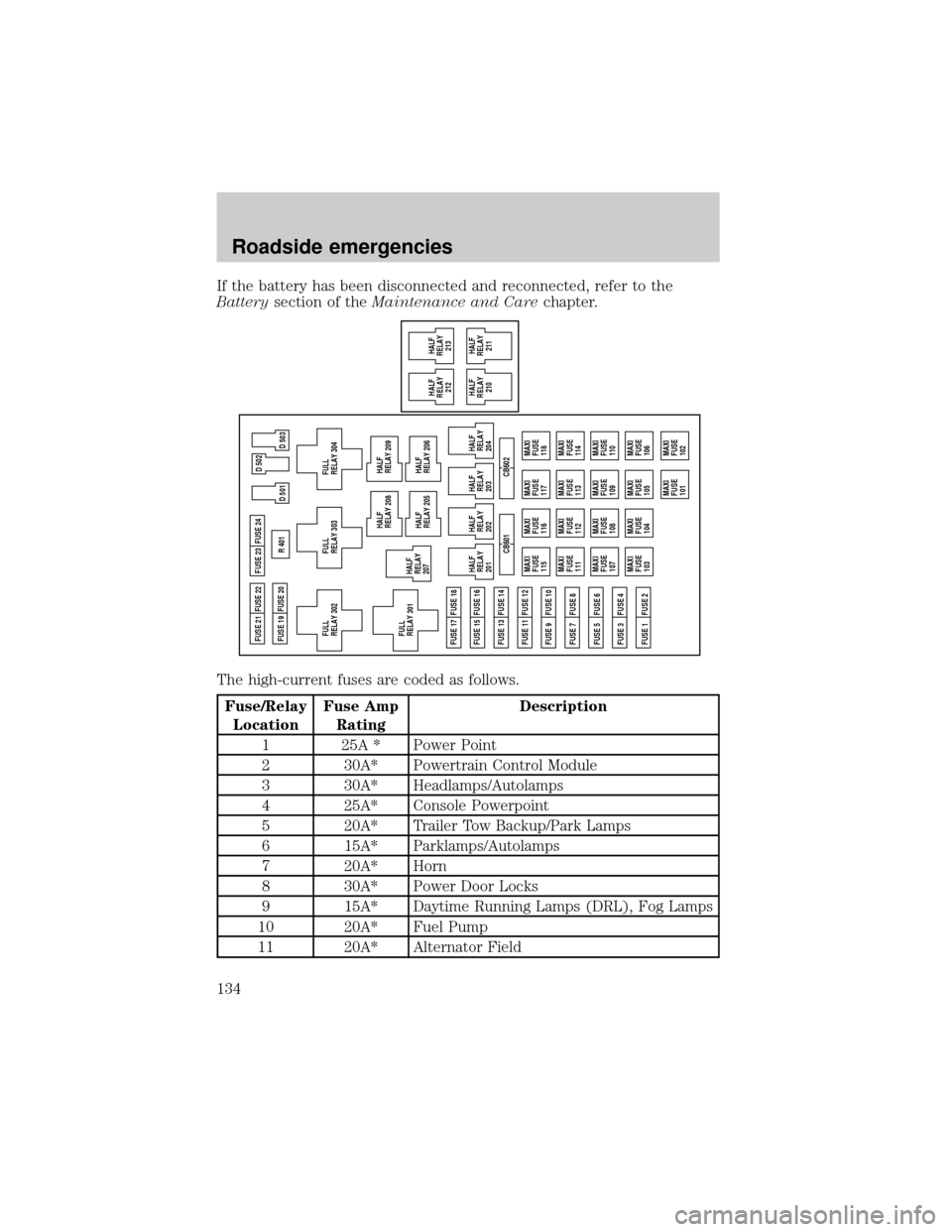
The high-current fuses are coded as follows.
Fuse/Relay
LocationFuse Amp
RatingDescription
1 25A * Power Point
2 30A* Powertrain Control Module
3 30A* Headlamps/Autolamps
4 25A* Console Powerpoint
5 20A* Trailer Tow Backup/Park Lamps
6 15A* Parklamps/Autolamps
7 20A* Horn
8 30A* Power Door Locks
9 15A* Daytime Running Lamps (DRL), Fog Lamps
10 20A* Fuel Pump
11 20A* Alternator Field
MAXI
FUSE
115MAXI
FUSE
116MAXI
FUSE
117
MAXI
FUSE
118
MAXI
FUSE
111MAXI
FUSE
112MAXI
FUSE
113
MAXI
FUSE
114
MAXI
FUSE
107MAXI
FUSE
108MAXI
FUSE
109
MAXI
FUSE
110
MAXI
FUSE
103MAXI
FUSE
104MAXI
FUSE
105
MAXI
FUSE
106
MAXI
FUSE
101MAXI
FUSE
102 CB601 CB602 FUSE 17 FUSE 18FUSE 21 FUSE 22
FUSE 19 FUSE 20FUSE 23
FULL
RELAY 302R 401
D 501 FUSE 24
FUSE 15 FUSE 16
FUSE 13 FUSE 14
FUSE 11 FUSE 12
FUSE 9 FUSE 10
FUSE 7 FUSE 8
FUSE 5 FUSE 6
FUSE 3 FUSE 4
FUSE 1 FUSE 2
D 503 D 502
FULL
RELAY 301HALF
RELAY
207
FULL
RELAY 303
FULL
RELAY 304
HALF
RELAY
201
HALF
RELAY
202HALF
RELAY 208
HALF
RELAY 209
HALF
RELAY 205
HALF
RELAY 206
HALF
RELAY
203
HALF
RELAY
204
HALF
RELAY
212
HALF
RELAY
210HALF
RELAY
213
HALF
RELAY
211
Roadside emergencies
134
Page 135 of 216

Fuse/Relay
LocationFuse Amp
RatingDescription
12 10A* Rear Wipers
13 Ð Not Used
14 Ð Not Used
15 10A* Running Board Lamps
16 Ð Not Used
17 Ð Not Used
18 15A* Powertrain Control Module, Fuel Injectors,
Fuel Pump, Mass Air Flow Sensor
19 10A* Trailer Tow Stop and Right Turn Lamp
20 10A* Trailer Tow Stop and Left Turn Lamp
21 Ð Not Used
22 Ð Not Used
23 15A* Powertrain Control Module, HEGO Sensors,
Canister Vent
24 15A* Powertrain C ontrol Module, Automatic
Transmission, CMS Sensor
101 30A** Trailer Tow Battery Charge
102 50A** Four Wheel Antilock Brake Module
103 50A** Junction Block Battery Feed
104 30A** 4x4 Shift Motor & Clutch
105 40A** Climate Control Front Blower
106 Ð Not Used
107 Ð Not Used
108 30A** Trailer Tow Electric Brake
109 50A** Air Suspension Compressor
110 30A** Moonroof, Flip Windows and Heated Seats
111 50A** Ignition Switch Battery Feed (Start Circuit)
112 30A** Drivers Power Seat, Adjustable Pedals
113 50A** Ignition Switch Battery Feed (Run and
Accessory Circuits)
114 30A** Climate Control Auxiliary Blower
115 Ð Not Used
Roadside emergencies
135
Page 137 of 216

CHANGING THE TIRES
If you get a flat tire while driving, do not apply the brake heavily.
Instead, gradually decrease your speed. Hold the steering wheel firmly
and slowly move to a safe place on the side of the road.
Spare tire information
Your vehicle is equipped with a spare tire that may be used as a spare or
a regular tire. The spare is identical to the other tires on your vehicle,
although the wheel trim may not match.
Location of the spare tire and tools
The spare tire and tools for your vehicle are stowed in the following
locations:
Item Location
Spare tire Under the vehicle, just forward of the rear
bumper
Jack, wheel nut wrench,
instructions, work glovesBehind the access panel located on the
right rear quarter panel interior trim
Jack handle On top of the radiator support at the front
of the engine compartment
Removing the jack handle
1. Open the hood.
2. Un-snap the end of the handle that is retained by the clip on the top
of the windshield washer bottle.
3. Un-snap the shaft of the handle from the two retaining clips attached
to the top of the radiator shroud.
Removing the jack and tools
1. Locate the access panel on the right rear quarter panel interior trim.
Lift and rotate the two panel retaining clips and remove the panel.
2. Un-snap the wheel lug nut wrench, instructions and work gloves from
their retaining bracket.
3. Remove the jack by turning the thumbwheel counterclockwise to
relieve tension against the stowage bracket.
Roadside emergencies
137