1999 FORD EXPEDITION instrument panel
[x] Cancel search: instrument panelPage 47 of 216
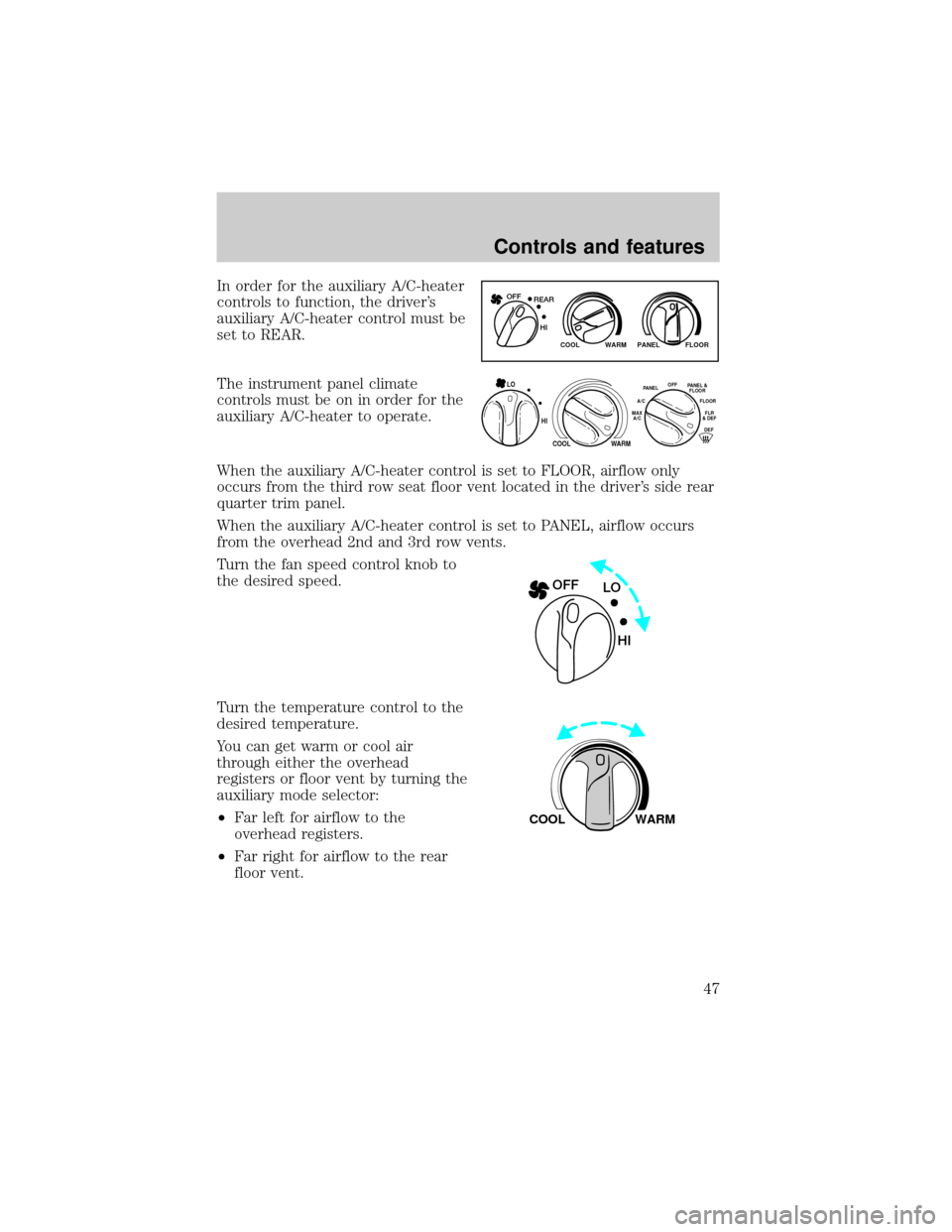
In order for the auxiliary A/C-heater
controls to function, the driver's
auxiliary A/C-heater control must be
set to REAR.
The instrument panel climate
controls must be on in order for the
auxiliary A/C-heater to operate.
When the auxiliary A/C-heater control is set to FLOOR, airflow only
occurs from the third row seat floor vent located in the driver's side rear
quarter trim panel.
When the auxiliary A/C-heater control is set to PANEL, airflow occurs
from the overhead 2nd and 3rd row vents.
Turn the fan speed control knob to
the desired speed.
Turn the temperature control to the
desired temperature.
You can get warm or cool air
through either the overhead
registers or floor vent by turning the
auxiliary mode selector:
²Far left for airflow to the
overhead registers.
²Far right for airflow to the rear
floor vent.
WARM PANEL FLOOR COOL
REAR OFF
HI
HI
COOL WARM
OFFPANELFLOOR
DEFFLR
& DEF A/C
MAX
A/CPANEL &
FLOOR
LO
LO OFF
HI
WARM COOL
Controls and features
47
Page 57 of 216
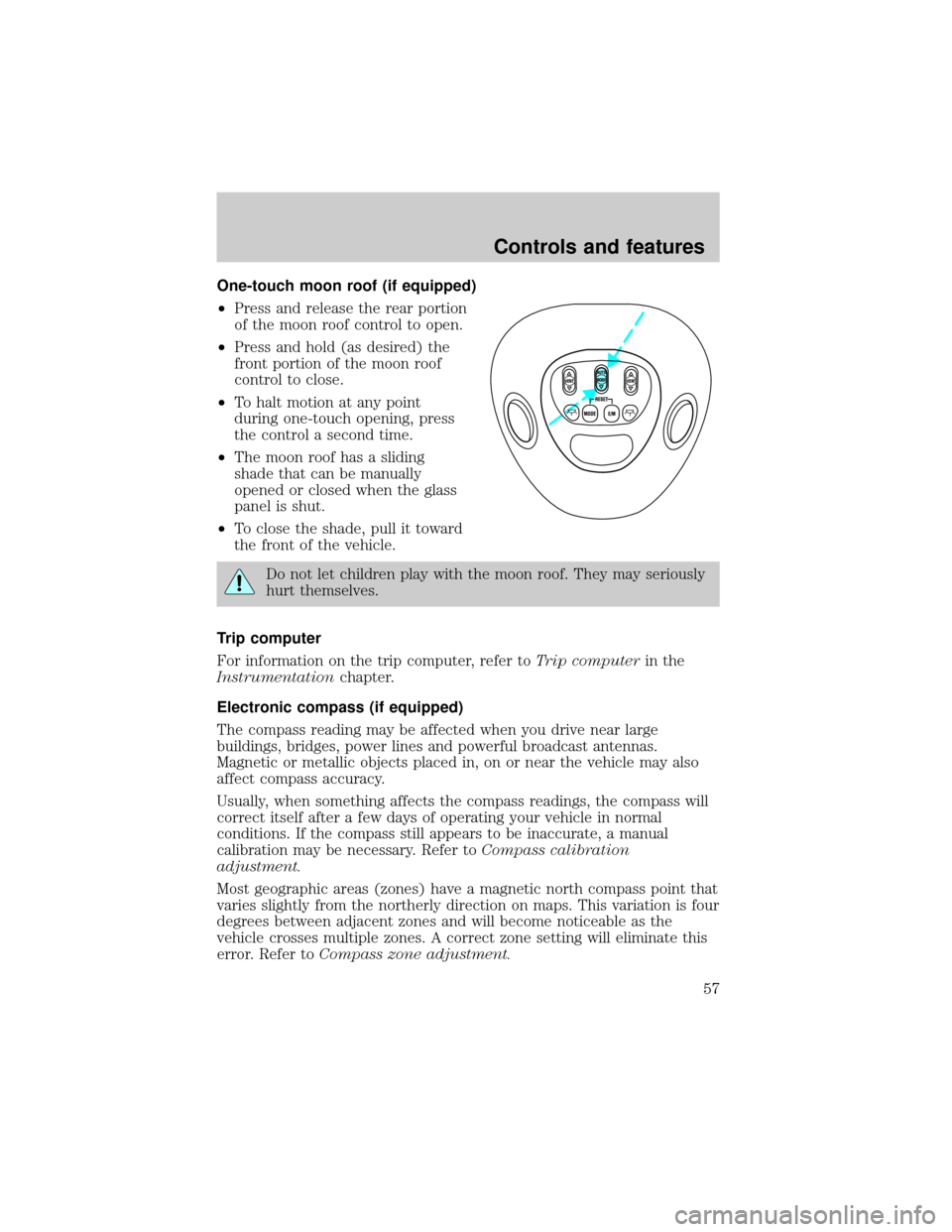
One-touch moon roof (if equipped)
²Press and release the rear portion
of the moon roof control to open.
²Press and hold (as desired) the
front portion of the moon roof
control to close.
²To halt motion at any point
during one-touch opening, press
the control a second time.
²The moon roof has a sliding
shade that can be manually
opened or closed when the glass
panel is shut.
²To close the shade, pull it toward
the front of the vehicle.
Do not let children play with the moon roof. They may seriously
hurt themselves.
Trip computer
For information on the trip computer, refer toTrip computerin the
Instrumentationchapter.
Electronic compass (if equipped)
The compass reading may be affected when you drive near large
buildings, bridges, power lines and powerful broadcast antennas.
Magnetic or metallic objects placed in, on or near the vehicle may also
affect compass accuracy.
Usually, when something affects the compass readings, the compass will
correct itself after a few days of operating your vehicle in normal
conditions. If the compass still appears to be inaccurate, a manual
calibration may be necessary. Refer toCompass calibration
adjustment.
Most geographic areas (zones) have a magnetic north compass point that
varies slightly from the northerly direction on maps. This variation is four
degrees between adjacent zones and will become noticeable as the
vehicle crosses multiple zones. A correct zone setting will eliminate this
error. Refer toCompass zone adjustment.
VENT VENTROOF
Controls and features
57
Page 66 of 216

Theft indicator
The theft indicator on top of the instrument panel will operate as
follows:
²When the ignition is OFF, the theft indicator will flash briefly every 2
seconds to indicate the SecuriLockysystem is protecting your
vehicle.
²When the ignition is turned to ON or START, the theft indicator will
light for 3 seconds and then go out. If the theft indicator stays on for
an extended period of time or flashes rapidly, have the system
serviced by your dealership or a qualified technician.
Programming spare SecuriLockYkeys
Spare SecuriLockykeys can be purchased from your dealership and
programmed to your SecuriLockyanti-theft system (up to a total of 8
keys). Your dealership can program your new SecuriLockykey(s) to
your vehicle or you can do it yourself using the following simple
procedure. To program a new SecuriLockykey yourself, you will need
two previously programmed SecuriLockykeys (keys that already
operate your vehicle's engine). If two previously programmed
SecuriLockykeys are not available (one or both of your original keys
were lost or stolen), you must bring your vehicle to your dealership to
have the spare SecuriLockykey(s) programmed.
Procedure to program spare SecuriLockYkeys to your vehicle
New SecuriLockykeys must have the correct mechanical key cut for
your vehicle.
Conventional (non-SecuriLocky) keyscannotbe programmed to your
vehicle.
You will need to have two previously programmed SecuriLockykeys and
the new unprogrammed SecuriLockykey readily accessible for timely
implementation of each step in the procedure. Please read and
understand the entire procedure before you begin.
1. Insert the first previously programmed SecuriLockykey into the
ignition and turn the ignition from OFF to RUN (maintain ignition in
RUN for at least one second).
2. Turn ignition to OFF and remove the first SecuriLockykey from the
ignition.
Controls and features
66
Page 67 of 216

3. Within five seconds of turning the ignition to OFF, insert the second
previously programmed SecuriLockykey into the ignition and turn the
ignition from OFF to RUN (maintain ignition in RUN for at least one
second but no more than 5 seconds).
4. Turn the ignition to OFF and remove the second SecuriLockykey
from the ignition.
5. Within 10 seconds of turning the ignition to OFF, insert the
unprogrammed SecuriLockykey (new key/valet key) into the ignition
and turn the ignition from OFF to RUN (maintain ignition in RUN for at
least one second). This step will program your new SecuriLockykey.
6. To program additional SecuriLockykey(s), repeat this procedure from
step 1.
If the programming procedure was successful, the new SecuriLocky
key(s) will start the vehicle's engine. The theft indicator (located on the
instrument panel) will light for three seconds and then go out.
If the programming procedure was not successful, the new SecuriLocky
key(s) will not operate the vehicle's engine. The theft indicator will flash
on and off. Wait at least one minute and then repeat the procedure from
step 1. If failure repeats, bring your vehicle to your dealership to have
the spare SecuriLockykey(s) programmed.
REMOTE ENTRY SYSTEM
Your vehicle is equipped with a remote entry system which allows you to:
²unlock the vehicle doors without a key.
²lock all the vehicle doors without a key
²activate the personal alarm.
The remote entry features only operate with the ignition in the OFF
position.
Controls and features
67
Page 110 of 216
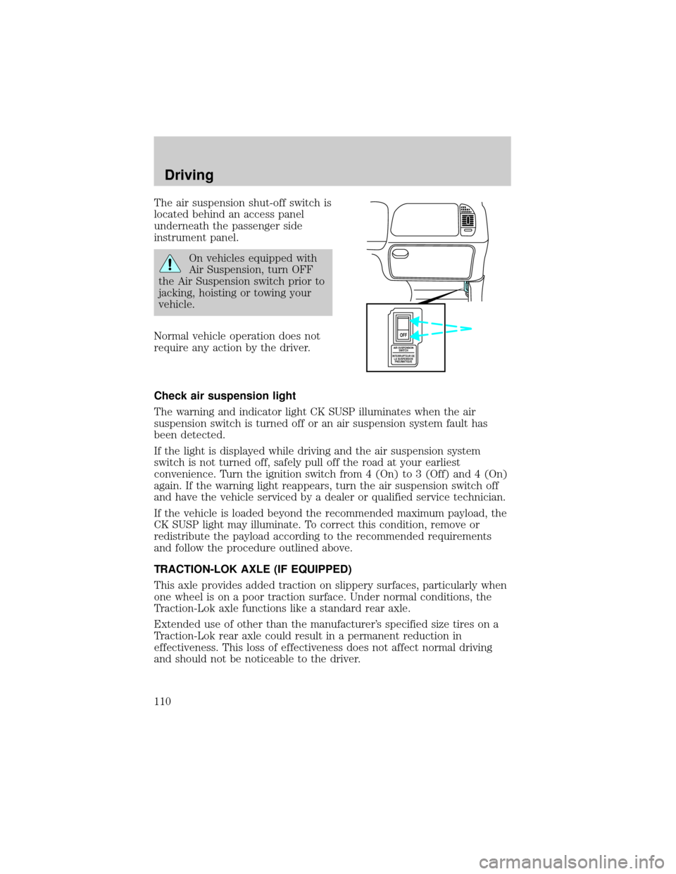
The air suspension shut-off switch is
located behind an access panel
underneath the passenger side
instrument panel.
On vehicles equipped with
Air Suspension, turn OFF
the Air Suspension switch prior to
jacking, hoisting or towing your
vehicle.
Normal vehicle operation does not
require any action by the driver.
Check air suspension light
The warning and indicator light CK SUSP illuminates when the air
suspension switch is turned off or an air suspension system fault has
been detected.
If the light is displayed while driving and the air suspension system
switch is not turned off, safely pull off the road at your earliest
convenience. Turn the ignition switch from 4 (On) to 3 (Off) and 4 (On)
again. If the warning light reappears, turn the air suspension switch off
and have the vehicle serviced by a dealer or qualified service technician.
If the vehicle is loaded beyond the recommended maximum payload, the
CK SUSP light may illuminate. To correct this condition, remove or
redistribute the payload according to the recommended requirements
and follow the procedure outlined above.
TRACTION-LOK AXLE (IF EQUIPPED)
This axle provides added traction on slippery surfaces, particularly when
one wheel is on a poor traction surface. Under normal conditions, the
Traction-Lok axle functions like a standard rear axle.
Extended use of other than the manufacturer's specified size tires on a
Traction-Lok rear axle could result in a permanent reduction in
effectiveness. This loss of effectiveness does not affect normal driving
and should not be noticeable to the driver.
AIR SUSPENSION
SWITCH
INTERRUPTEUR DE
LA SUSPENSION
PNEUMATIQUE
OFF
Driving
110
Page 114 of 216
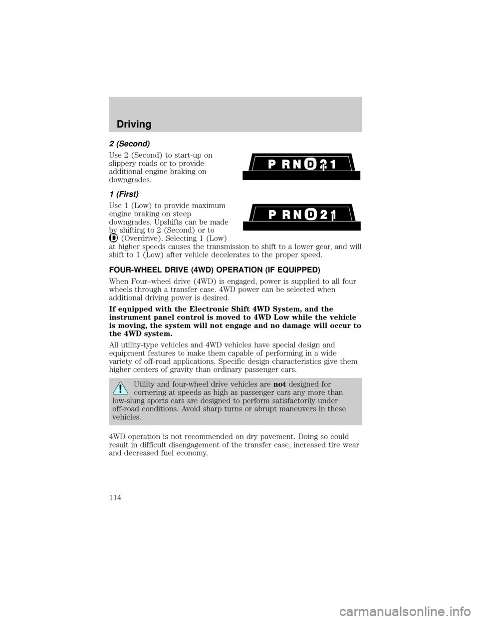
2 (Second)
Use 2 (Second) to start-up on
slippery roads or to provide
additional engine braking on
downgrades.
1 (First)
Use 1 (Low) to provide maximum
engine braking on steep
downgrades. Upshifts can be made
by shifting to 2 (Second) or to
(Overdrive). Selecting 1 (Low)
at higher speeds causes the transmission to shift to a lower gear, and will
shift to 1 (Low) after vehicle decelerates to the proper speed.
FOUR-WHEEL DRIVE (4WD) OPERATION (IF EQUIPPED)
When Four±wheel drive (4WD) is engaged, power is supplied to all four
wheels through a transfer case. 4WD power can be selected when
additional driving power is desired.
If equipped with the Electronic Shift 4WD System, and the
instrument panel control is moved to 4WD Low while the vehicle
is moving, the system will not engage and no damage will occur to
the 4WD system.
All utility-type vehicles and 4WD vehicles have special design and
equipment features to make them capable of performing in a wide
variety of off-road applications. Specific design characteristics give them
higher centers of gravity than ordinary passenger cars.
Utility and four-wheel drive vehicles arenotdesigned for
cornering at speeds as high as passenger cars any more than
low-slung sports cars are designed to perform satisfactorily under
off-road conditions. Avoid sharp turns or abrupt maneuvers in these
vehicles.
4WD operation is not recommended on dry pavement. Doing so could
result in difficult disengagement of the transfer case, increased tire wear
and decreased fuel economy.
Driving
114
Page 122 of 216
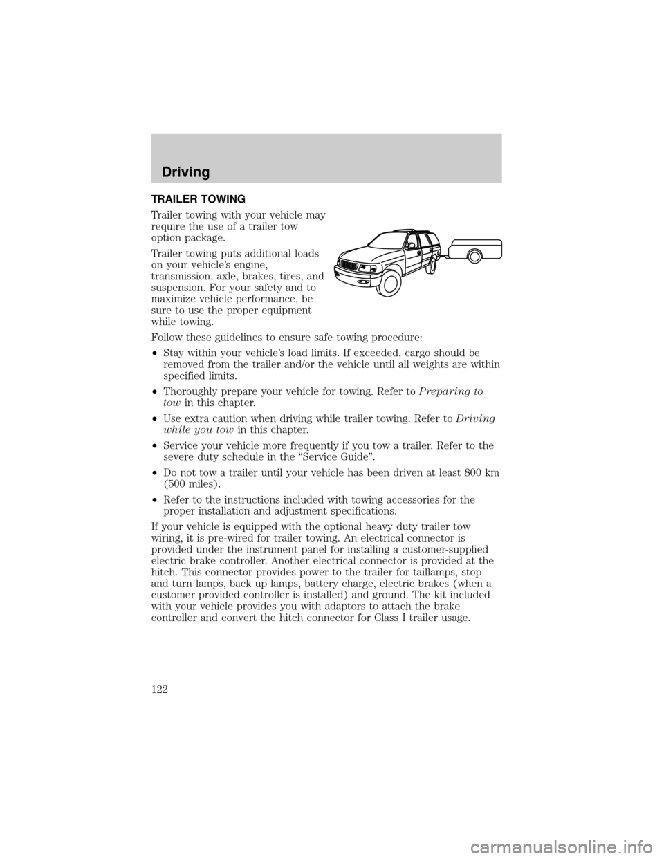
TRAILER TOWING
Trailer towing with your vehicle may
require the use of a trailer tow
option package.
Trailer towing puts additional loads
on your vehicle's engine,
transmission, axle, brakes, tires, and
suspension. For your safety and to
maximize vehicle performance, be
sure to use the proper equipment
while towing.
Follow these guidelines to ensure safe towing procedure:
²Stay within your vehicle's load limits. If exceeded, cargo should be
removed from the trailer and/or the vehicle until all weights are within
specified limits.
²Thoroughly prepare your vehicle for towing. Refer toPreparing to
towin this chapter.
²Use extra caution when driving while trailer towing. Refer toDriving
while you towin this chapter.
²Service your vehicle more frequently if you tow a trailer. Refer to the
severe duty schedule in the ªService Guideº.
²Do not tow a trailer until your vehicle has been driven at least 800 km
(500 miles).
²Refer to the instructions included with towing accessories for the
proper installation and adjustment specifications.
If your vehicle is equipped with the optional heavy duty trailer tow
wiring, it is pre-wired for trailer towing. An electrical connector is
provided under the instrument panel for installing a customer-supplied
electric brake controller. Another electrical connector is provided at the
hitch. This connector provides power to the trailer for taillamps, stop
and turn lamps, back up lamps, battery charge, electric brakes (when a
customer provided controller is installed) and ground. The kit included
with your vehicle provides you with adaptors to attach the brake
controller and convert the hitch connector for Class I trailer usage.
Driving
122
Page 149 of 216
Do not start your engine with the air cleaner removed and do
not remove it while the engine is running.
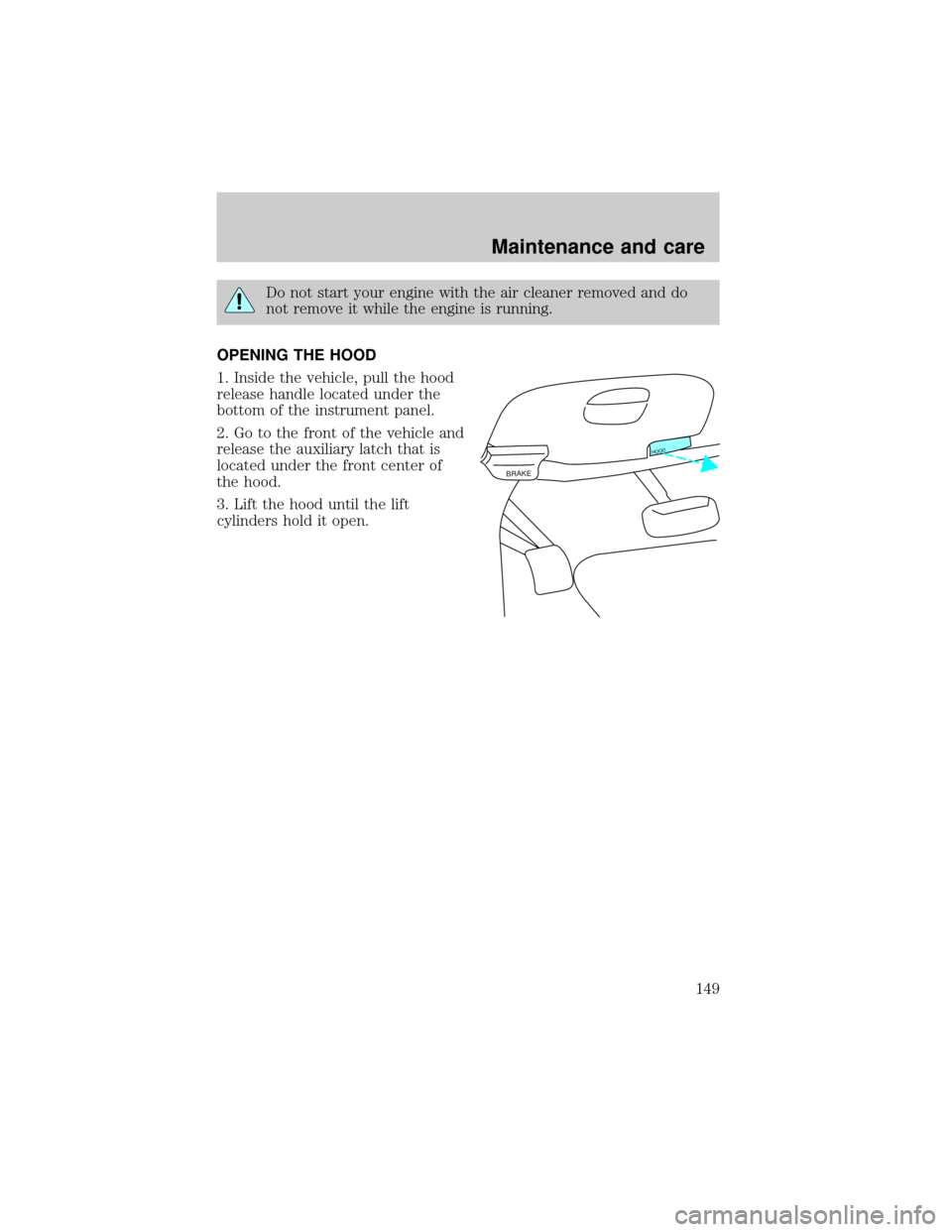
OPENING THE HOOD
1. Inside the vehicle, pull the hood
release handle located under the
bottom of the instrument panel.
2. Go to the front of the vehicle and
release the auxiliary latch that is
located under the front center of
the hood.
3. Lift the hood until the lift
cylinders hold it open.
BRAKE
HOOD
Maintenance and care
149