1999 FORD E SERIES cooling
[x] Cancel search: coolingPage 5 of 39

Fast start glow plug system
The glow plug system consists of:
²eight glow plugs
²the glow plug relay
²engine oil temperature (EOT) sensor
²barometric pressure (BARO) sensor
The glow plug system is electronically controlled by the PCM. The PCM
energizes the glow plugs immediately after the ignition is placed in the
ON position, then determines how long the glow plugs will be on
according to the EOT and BARO sensors. The required time for the glow
plugs to be energized decreases as the engine oil temperature and
barometric pressure increase.
Engine cooling system
The cooling system contains an engine oil cooler which is mounted to
the side of the cylinder block. The cooler's function is to regulate engine
oil temperature.
Engine governed speed
The engine governor is controlled by the PCM. The PCM controls fuel
input to limit maximum engine speed. It will not, however, prevent
engine overspeeding resulting from downshifting at high vehicle speed or
by descending steep grades at too high a vehicle speed for the selected
transmission gear.
For maximum vehicle speed in various gears, refer to the ªTransmission
shift speedº chart in theDriving tipschapter. Do not exceed 3,600 rpm.
Maximum engine governed speed is 3,000±4,000 rpm depending on
engine load. Excessive rpm can only be achieved by manually
downshifting at too high of a vehicle speed.
Operating the engine beyond the governed speed can cause severe
engine damage.
Diesel information
5
Page 11 of 39

Operation in standing water
Ingestion of water into the diesel engine can result in immediate and
severe damage to the engine. If driving through water, slow down to
avoid splashing water into the intake. If the engine stalls, and ingestion
of water into the engine is suspected, do not try to restart the engine.
Consult your dealer for service immediately. Follow the cylinder
compression test procedure outlined in the Workshop Manual, then
check the engine oil for contamination.
Engine block heater (if equipped)
Refer to theStartingchapter in your Owner Guide.
JUMP STARTING YOUR VEHICLE
The gases around the battery can explode if exposed to flames,
sparks, or lit cigarettes. An explosion could result in injury or
vehicle damage.
Do not push start your vehicle. You could damage the catalytic
converter.
Batteries contain sulfuric acid which burns skin, eyes, and
clothing.
Preparing your vehicle
Also see the label on the battery.
1. Use only a 12±volt supply to start your vehicle. If you connect your
battery to a 24±volt power supply you can damage your starter, ignition
system and other electrical components. Do not attach the jumper cables
to the glow plug relay as this could severely damage the glow plugs,
injector driver module and PCM.
2. Do not disconnect the battery of the disabled vehicle as this could
damage the vehicle's electrical system.
3. Park the booster vehicle close to the hood of the disabled vehicle
making sure theydo nottouch. Set the parking brake on both vehicles
and stay clear of the engine cooling fan and other moving parts.
Starting
11
Page 28 of 39

ENGINE COOLANT
Replacing coolant
A coolant mixture of 50% coolant concentrate and 50% water is
recommended to maintain best overall performance. To avoid damaging
the engine and radiator, the coolant concentrate should not exceed 60%.
When refilling the coolant system either as part of the regular
maintenance (48 months, or 80 000 km [50 000 miles], whichever comes
first and then every 36 months or 48 000 km [30 000 miles], whichever
comes first), or due to service performed, adhere to the following
instructions:
1. Drain and flush the cooling system to remove dirt deposits, oil, rust
particles.
2. Add 1.89L (4 pints) of supplemental coolant additive FW-15, directly
to the cooling system. An additional 237±295 ml (8±10 oz.) of
supplemental coolant additive FW-15 should be added at 24 000 km (15
000 mile) intervals to maintain proper concentration.
3. Fill the coolant reservoir with the specified coolant/water mixture until
the level stabilizes at the top hose fitting. Replace and tighten cap. Fill
the radiator when cold. Level the coolant in the coolant bottle.
4. Reinstall the coolant bottle cap.
5. Start and idle engine until the radiator upper hose is warm
(approximately 10±15 minutes). If the hose does not get warm then
repeat at a higher engine speed.
6. Immediately shut off engine. Cautiously remove coolant bottle cap and
add coolant to Cold Fill mark.
Checking coolant level
Check coolant level in coolant reservoir bottle at least once a month,
only when the engine is cool. Fill to within the ªCold Fill Levelº range
noted on the reservoir as required with a 50/50 mixture of coolant
concentrate and water.
A coolant mixture of 50% coolant concentrate and 50% water is
recommended to maintain best overall performance. A 60/40 antifreeze
to water ratio is acceptable for extremely cold climates, but must be
returned to a 50/50 ratio at the end of the winter season.
Vehicles with diesel engines typically are used to carry heavy loads and
accumulate mileage rapidly. These two factors cause the additives in the
General maintenance information
28
Page 29 of 39

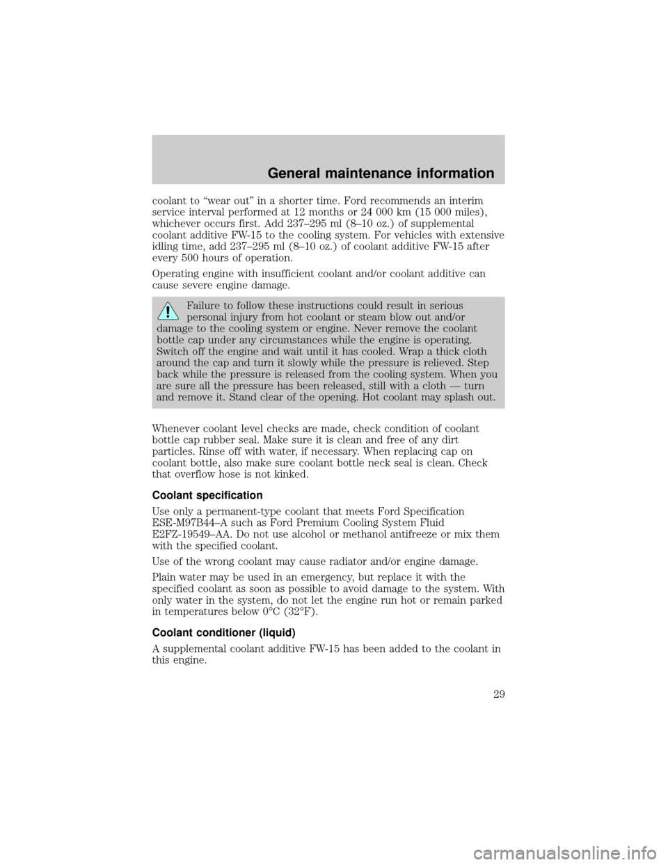
coolant to ªwear outº in a shorter time. Ford recommends an interim
service interval performed at 12 months or 24 000 km (15 000 miles),
whichever occurs first. Add 237±295 ml (8±10 oz.) of supplemental
coolant additive FW-15 to the cooling system. For vehicles with extensive
idling time, add 237±295 ml (8±10 oz.) of coolant additive FW-15 after
every 500 hours of operation.
Operating engine with insufficient coolant and/or coolant additive can
cause severe engine damage.
Failure to follow these instructions could result in serious
personal injury from hot coolant or steam blow out and/or
damage to the cooling system or engine. Never remove the coolant
bottle cap under any circumstances while the engine is operating.
Switch off the engine and wait until it has cooled. Wrap a thick cloth
around the cap and turn it slowly while the pressure is relieved. Step
back while the pressure is released from the cooling system. When you
are sure all the pressure has been released, still with a cloth Ð turn
and remove it. Stand clear of the opening. Hot coolant may splash out.
Whenever coolant level checks are made, check condition of coolant
bottle cap rubber seal. Make sure it is clean and free of any dirt
particles. Rinse off with water, if necessary. When replacing cap on
coolant bottle, also make sure coolant bottle neck seal is clean. Check
that overflow hose is not kinked.
Coolant specification
Use only a permanent-type coolant that meets Ford Specification
ESE-M97B44±A such as Ford Premium Cooling System Fluid
E2FZ-19549±AA. Do not use alcohol or methanol antifreeze or mix them
with the specified coolant.
Use of the wrong coolant may cause radiator and/or engine damage.
Plain water may be used in an emergency, but replace it with the
specified coolant as soon as possible to avoid damage to the system. With
only water in the system, do not let the engine run hot or remain parked
in temperatures below 0ÉC (32ÉF).
Coolant conditioner (liquid)
A supplemental coolant additive FW-15 has been added to the coolant in
this engine.
General maintenance information
29
Page 30 of 39

This additive aids in the prevention of rust and scale buildup on the
internal parts of the cooling system. Prevention of rust and scale buildup
allows for proper dissipation of heat generated by combustion.
See the ªService Guideº for recommended intervals.
EMISSION CONTROL SYSTEM(S) LAWS
Federal law prohibits vehicle manufacturers, dealers and other persons
engaged in the business of repairing, servicing, selling, leasing or trading
motor vehicles as well as fleet operations from unknowingly removing or
rendering emission control system(s) inoperative. Further, modifications
of the emission control system(s) could create liability on the part of the
individual owners under the laws of some states. In Canada,
modifications of the emission control system(s) could create liability
under applicable Federal or Provincial laws.
Do not remove or alter the original equipment floor covering or
insulation between it and the metal floor of the vehicle. The floor
covering and insulation protect occupants of the vehicle from the engine
and exhaust system heat and noise. On vehicles with no original
equipment floor covering insulation, do not carry passengers in a manner
that permits prolonged skin contact with the metal floor. Provide
adequate insulation.
NOISE EMISSIONS WARRANTY, PROHIBITED TAMPERING ACTS
AND MAINTENANCE
On January 1, 1978, Federal regulation became effective governing the
noise emission on trucks over 4 536 kg (10 000 lbs.) GVWR (Gross
Vehicle Weight Rating). The following statements concerning prohibited
tampering acts and maintenance, and the noise warranty found in the
Warranty Facts Booklet, are applicable to complete chassis cabs over
4 536 (10 000 lbs.) GVWR.
Tampering with noise control system prohibited
Federal law prohibits the following acts or the causing thereof: (1) The
removal or rendering inoperative by any person other than for purposes
of maintenance, repair or replacement of any device or element of design
incorporated into any new vehicle for the purpose of noise control prior
to its sale or delivery to the ultimate purchaser or while it is in use, or
(2) the use of the vehicle after such device or element of design has
been removed or rendered inoperative by any person.
General maintenance information
30
Page 35 of 39

IF THE ENGINE RUNS HOT
The following could cause the engine to overheat:
²Lack of coolant.
²Dirty cooling system.
²Driving with frozen coolant.
²Sticking thermostat.
²Overloading or pulling heavy trailers during hot weather.
²Grill or radiator air blockage.
²Slipping or missing drive belt.
²Plugged or very dirty air cleaner element.
IF FUSES BURN OUT
Burned-out or blown fuses usually indicate an electrical short-circuit,
although a fuse may occasionally burn out from vibration. Insert a second
fuse. If this fuse immediately burns out and you cannot locate the cause,
return your vehicle to your dealer for a circuit check.
Replacement fuses and circuit breakers must always be the same
rating as the original equipment shown. Never replace a fuse or
circuit breaker with one of a higher rating. Higher rated fuses or circuit
breakers could allow circuit overloading in the event of a circuit
malfunction, resulting in severe vehicle damage or personal injury.
Refer to the ªOwner Guideº for replacement of fuses.
Minor troubleshooting guide
35
Page 36 of 39

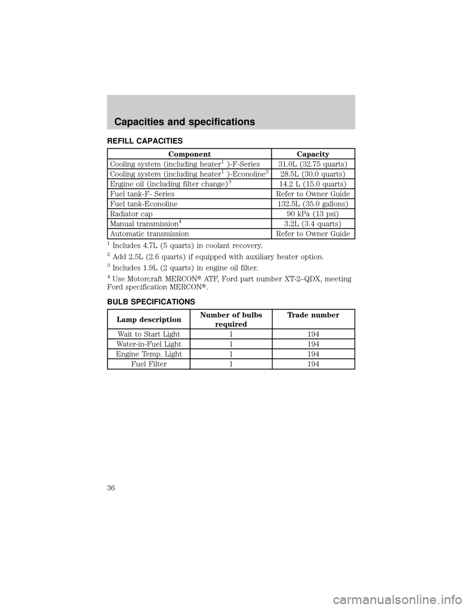
REFILL CAPACITIES
Component Capacity
Cooling system (including heater1)-F-Series 31.0L (32.75 quarts)
Cooling system (including heater1)-Econoline228.5L (30.0 quarts)
Engine oil (including filter change)314.2 L (15.0 quarts)
Fuel tank-F- Series Refer to Owner Guide
Fuel tank-Econoline 132.5L (35.0 gallons)
Radiator cap 90 kPa (13 psi)
Manual transmission
43.2L (3.4 quarts)
Automatic transmission Refer to Owner Guide
1Includes 4.7L (5 quarts) in coolant recovery.
2Add 2.5L (2.6 quarts) if equipped with auxiliary heater option.
3Includes 1.9L (2 quarts) in engine oil filter.
4Use Motorcraft MERCONtATF, Ford part number XT-2±QDX, meeting
Ford specification MERCONt.
BULB SPECIFICATIONS
Lamp descriptionNumber of bulbs
requiredTrade number
Wait to Start Light 1 194
Water-in-Fuel Light 1 194
Engine Temp. Light 1 194
Fuel Filter 1 194
Capacities and specifications
36
Page 37 of 39

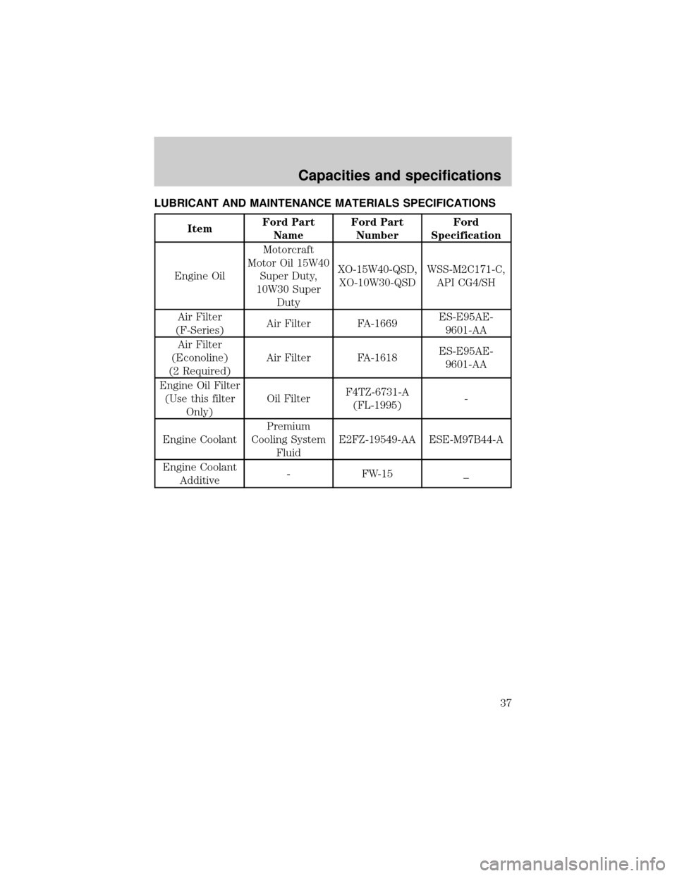
LUBRICANT AND MAINTENANCE MATERIALS SPECIFICATIONS
ItemFord Part
NameFord Part
NumberFord
Specification
Engine OilMotorcraft
Motor Oil 15W40
Super Duty,
10W30 Super
DutyXO-15W40-QSD,
XO-10W30-QSDWSS-M2C171-C,
API CG4/SH
Air Filter
(F-Series)Air Filter FA-1669ES-E95AE-
9601-AA
Air Filter
(Econoline)
(2 Required)Air Filter FA-1618ES-E95AE-
9601-AA
Engine Oil Filter
(Use this filter
Only)Oil FilterF4TZ-6731-A
(FL-1995)-
Engine CoolantPremium
Cooling System
FluidE2FZ-19549-AA ESE-M97B44-A
Engine Coolant
Additive- FW-15 _
Capacities and specifications
37