1999 BMW 540i key
[x] Cancel search: keyPage 411 of 1002

Downloaded from www.Manualslib.com manuals search engine
Fuel lniection 1
Table b. Siemens MS 41.1 ECM pin assignments (continued)
Pin
lSiqnal 1 Componentlfunction / Notes I - I I
40 1 ground /Crankshaft position sensor /crankshaft position sensor control I - I I
41 1 ground /Camshaft position sensor (CMP) /shielding for CMP sensor I - I I
42 1 ground I~hrottie position sensor (TPS) /TPS ground
43
44
45
46
47
48
49
50
51 ground
output
output
output
outout
I I I
input
52 53
54
55
56 57
58
59
60
61
62
63
64
65
66 Camshaft position sensor (CMP)
Throttle position sensor (TPS)
Throttle position sensor (traction control)
Instrument cluster
Not used
Crankshaft position sensor (Hall effect)
I~ot used
I I I
Fuel pump relay control Camshaft
positionlrpm sensor control
Voltage
supply to TPS (5 vdc)
ABSIASC module
Instrument cluster, fuel reserve signal
Crankshaft position sensor control
Power supply (terminal 15)
Not used
Not used
output input
ground
ground
output
input
output
inputloutput
ground
output
input
input
input
I I
Battery voltage with key on or engine running
Oxygen sensor signal ground
67
Idle speed control valve
Power supply
Oxygen sensor heater (no. 2 in front catalytic
converter)
Ignition circuit
Knock sensor
(cyl. 1-3)
Knock sensor (cyl. 1-3)
Knock sensor
(cyl4-6)
Data linic connector (TxD)
Oxygen sensor heater (no. 2 behind catalytic
converter)
Secondary air injection
Knock sensor (cyl. 4-6)
Camshaft
positionlrpm sensor
Camshaft
positionlrpm sensor
Not used
Pulse ground with engine at normal temperature with
varying engine load
68 Pulsed ground-close signal (see
pin 26)
Battery voltage from main relay (terminal 87)
Oxygen sensor heater ground
Ignition circuit monitoring signal
Knock sensor
Knock sensor signal
Knock sensor
Diagnostic
TxD (transmit) signal to pin 18 in data link
connector
Oxygen sensor heater ground
Secondary air injection control
valve
Knocic sensor signal
Camshaft positionlrpm sensor control
Camshaft
positionlrpm sensor control
ground Oxygen sensor
(no.
1 in front of catalytic
converter)
output Evaporative purge
valve control
Page 601 of 1002

Downloaded from www.Manualslib.com manuals search engine
Gearshift ~inkaael
Gearshift lever, removing
(manual transmission)
Use the accompanying illustration as a guide when removing
and installing the gearshift linkage.
- Remove shift knob by pulling knob straight off shift lever.
NOTE-
Pull up on the shift knob with about 90 lbs. of force. Do not
twist
knob or locating key can be damaged.
- Squeeze sides of shift boot to unclip from center console.
Pull boot up and off shift lever.
- Remove sound insulation at base of shift lever.
- Raise vehicle to gain access to underside of vehicle.
- --
WARNING-
Male sure the car is stable and well supported at all tfmes.
Use a professional automotwe hft orjaclc stands designed for
the purpose.
A floorjaclc 1s not adequate support.
- Remove complete exhaust system. See 180 Exhaust
System.
- Remove driveshaft. See 260 Driveshaft.
- Support transmission with transmission jack. Remove
crossmember from rear of transmission.
- Lower rear of transmission to access gearshift linkage.
CA UTIOI\C
Tilting the engine to lower the transmission can lead to
damage to various components due to lack of clearance.
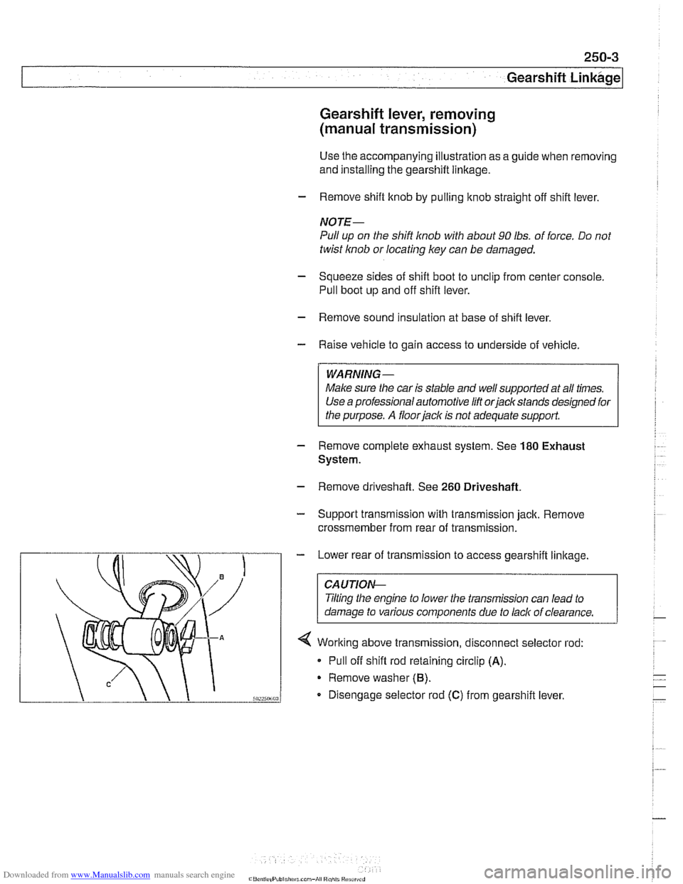
4 Working above transmission, disconnect selector rod:
* Pull off shift rod retaining circlip (A).
Remove washer (6).
Disengage selector rod (C) from gearshift lever.
Page 606 of 1002

Downloaded from www.Manualslib.com manuals search engine
250-8
Gearshift Linkage
-;Ag Gate "",?it.,
Shift interlock, checking function
(automatic transmission)
4 The shift interlock uses a cable between the ignition switch
and the shift lever to lock the shift lever in the park position
when the key is in the off position or removed. This feature
also prevents the key
from being removed from the ignition
lock until the selector lever is in Park.
Shift selector lever to Park position and turn ignition key to
the off position.
Remove ignition key. Checlc that selector lever cannot be
shifted out of Park position.
Turn ignition lkey on and depress
brake pedal. Checlc that
selector lever moves freely from gear to gear.
With selector lever in a gear position other than Park, at-
tempt to turn lkey to off position and remove. Key should not
go into off position.
If any faults are found check cable for lkinks and
check
cable attachment points for damage or faults.
NOTE-
* It must only be possible to remove ignition ley with
selector lever
in Park position.
* Do not link shift interlocl( cable.
Shift interlock repair is covered
in 320 Steering and
Wheel Alignment.
Page 670 of 1002

Downloaded from www.Manualslib.com manuals search engine
I Steering and Wheel Alignment
With ignition key in ON position (60" from LOCKED):
- Disconnect ring antenna harness connector.
Insert
BMW special tool 32 3 110 or a thin piece of stiff wire
into opening (arrow) in lock cylinder.
Turn tool forward (clockwise) approximately 90" and re-
move lock cylinder.
* Reinstallation is reverse of removal.
NOTE-
Using the valet ley during this procedure will provide better
access to lock opening.
Steering column lock, removing and
installing
- Disconnect negative (-) cable from battery.
CAUTIO&
Prior to disconnecting the battery, read the battery discon-
nection cautions given
in 001 General Cautions and
Warnings.
- Remove steering wheel as described earlier.
- Remove steering column trim panels as described earlier.
- Remove collar and circlip from steering shaft. Refer to illus-
tration of steering column components.
4 Pry steering shaft bearing with inner sleeve out of lock hous-
ing.
- Remove ring antenna as described earlier.
- Remove column switches. See 612 Switches.
< Automatic transmission models: Loosen and disconnect in-
terloclc shift cable (arrow) from ignition lock assembly.
Page 672 of 1002

Downloaded from www.Manualslib.com manuals search engine
320-1 4
Steering and Wheel Alignment
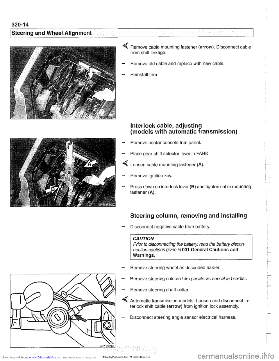
Remove cable mounting fastener (arrow). Disconnect cable
from shift
linkage.
Remove old cable and replace with new cable.
Reinstall trim.
Interlock cable, adjusting
(models with automatic transmission)
- Remove center console trim panel.
- Place gear shift selector lever in PARK.
4 Loosen cable mounting fastener (A).
- Remove ignition key.
- Press down on interlock lever (B) and tighten cable mounting
fastener (A).
Steering column, removing and installing
- Disconnect negative cable from battery.
CAUTIOI\C
Prior to disconnecting the battea read the battery discon-
nection cautions given
in 001 General Cautions and
Warninqs.
- Remove steering wheel as described earlier.
m
- Remove steering column trim panels as described earlier.
' \L/>I - Remove steerinq shaft collar
Automatic transmission models: Loosen and disconnect in-
terlock shift cable (arrow) from ignition lock assembly.
4 - Disconnect steering angle sensor electrical harness.
Page 777 of 1002

Downloaded from www.Manualslib.com manuals search engine
340-1 5
Brakes
- Remainder of installation is reverse of removal.
- Clean brake caliper mounting bolts (7 mm Allen). Replace
ones which are not in perfect condition. Do not grease.
Top up brake fluid to MAX marking.
- Before driving car, pump bralte pedal several times so that
brake pads contact brake rotors.
Check that brake fluid level is correct. Top up if necessary.
Hold ignition key for at least
30 seconds in accessory po-
sition without starting engine. This clears any fault codes in
memory and turns off brake pad warning light.
Tightening torques Brake caliper to pad carrier
(7 mm Allen)
Front caliper
30 Nm (22 It-lb)
- Rear caliper 28 Nm (21 It-lb)
Road wheel to hub
120i 10 Nm (89i7 ft-lb)
Brake rotors, removing and installing
- Raise car and remove wheels
WARNING-
Male sure that the car is firmly supported on jack stands de-
signed for the purpose. Place jack stands beneath structural
chassis points. Do not place jack stands under suspension
parts.
Remove brake caliper carrier bolts (arrows). Suspend brake
caliper from chassis using stiff wire.
NOTE-
Hydraulic brake line remains connected.
4 Remove bralte rotor mounting screw (arrow) and remove ro-
tor.
- Inspect rotor for cracks, signs of overheating and scoring.
- Minimum allowable thickness (MIN TH) is stamped on rotor
hub. Measure rotor braking surface with a micrometer at
eight to ten different points and use the smallest measure-
ment. Compare to specifications in table below.
- If rotor does not pass minimum thickness requirements or is
damaged, replace rotor.
Page 792 of 1002

Downloaded from www.Manualslib.com manuals search engine
1 Brakes
- Remove precharge pump mounting bracket fasteners and re-
move pump.
- Installation is reverse of removal, noting the following:
Be sure to replace rubber pump mounts if damaged
01
worn.
Bleed brakes as described earlier.
Tightening torque Brake line
to precharge pump 18 Nrn (13 ft-lb)
DSC pressure sensor (1 999 - 2002 models)
On 1999 and later DSC systems, the DSC pressure sensor is
screwed into the DSC hydraulic unit (right rear of engine com-
partment).
WARNING-
* €39 cars require special BMW service equipment to prop-
erly bleed the brakes. Removal of the
DSCpressure sensor
is not recommended unless this equipment is available. For
safety reasons, the brake system on cars with ABS must be
bled using the procedures described in this repair group.
Switch off ignition and remove
key to male sure brake
system cannot be activated.
- Disconnect electrical harness connector at switch.
- Use BMW special tool 34 5 160 to remove and install sensor.
Inspect threads and sealing surfaces for damage.
* Work quicltly to avoid excessive brake fluid leakage.
Tightening torque
Pressure sensor
to hydraulic 19 Nrn (14ft-lb)
unit
- Reconnect harness connector
- Bleed front brakes as described earlier.
- Press on brakes and check for leaks at sensor.
- Turn on ignition and firmly depress brake pedal. Check that
DSC warning light does not come on.
Page 803 of 1002

Downloaded from www.Manualslib.com manuals search engine
400-9
Body-General
Battery safety terminal
(BST)
4 Starting with 1999 models (9198 production and later), a py-
rotechnic (explosive charge) device automatically discon-
nects the battery positive terminal during impacts. Key
features,
like power windows and door locks, remain opera-
tional.
Security
Electronic immobilization (EWS)
Ignition key transponder signal All
E39 vehicles incorporate an electronic immobilization sys-
tem known as EWS. This svstem uses a wireless comrnuni-
cation link between a transponder chip in the ignition key and
the ring antenna surrounding the ignition switch. The EWS
control module blocks the starting of the vehicle unless the
correct coded ignition key is used.
NOTE-
Electronic immobilization is sometimes referred to as the
driveaway protection system.
Antitheft alarm (DWA)
This is adealer-installed option for which the E39 vehicles are
factory-wired. When armed, the system monitors door
loci(
contacts and trunk and engine hood locks and sounds a siren
if it detects tampering.
E39 interiors have a unique character, with a combination
of
sporty features and innovativedesign. All body versions were
made in a wide choice of interior and exterior colors. New col-
ors with matching leather or leatherette upholstery were intro-
duced for each model year.
Driving
comfort is enhanced by power steering, tilt steering
wheel, height-adjustable front seats, and electrically adjust-
able and heated rear-view mirrors. Inside the car there are
reading lights at four seating positions.