1999 BMW 525i heater
[x] Cancel search: heaterPage 104 of 1002

Downloaded from www.Manualslib.com manuals search engine
113-10
Cylinder Head Removal and Installation
4 Working above engine, disconnect the following:
Vent line from cylinder head cover
(A).
. Oxygen sensor connectors (B).
Electrical harness connector from VANOS solenoid
valve
(C).
Electrical harness connectors at throttle valve position
switch
(D), ASC valve position switch (E), fuel injector har-
ness
(F) and vent valve (G).
CAUTION-
Be sure to mark oxygen sensor harness connectors so that
they can be reassembled correctly Do not interchange con-
nectors.
4 Where applicable, remove schraeder valve cap (arrow) from
air connection on fuel rail. Using a tire chuck, blow fuel back
through feed line using a brief burst of compressed air (max-
imum of
3 bar or 43.5 psi).
WARNING-
. Fuel in fuel line is underpressure (approx. 3 - 5 bar or 45 -
75 psi) and may be expelled. Do not smoke or work near
heaters or other fire hazards. Keep a fire extinguisher
handy Before disconnecting fuel hoses, wrap a cloth
around fuel hoses to absorb any leaking fuel. Catch and
dispose of escaped fuel. Plug open fuel lines.
- Always unscrew the fuel rank cap ro release pressure
;n the tank before working on the tank or lines.
Disconnect fuel lines by sliding locking collar in (arrows) and
pulling lines apart.
NOTE-
BMW uses three styles of fuel line connections; a one-time
use
clamp; a locking fitting that uses BMWspecial tool 16 1
050 to release; and a quick release sleeve (above) that dis-
connects the line when depressed.
Page 118 of 1002

Downloaded from www.Manualslib.com manuals search engine
. .- -
Cylinder Head Removal and Installation
- Working at side of intake manifold near left strut tower, dis-
connect intake manifold resonance valve electrical harness
connector.
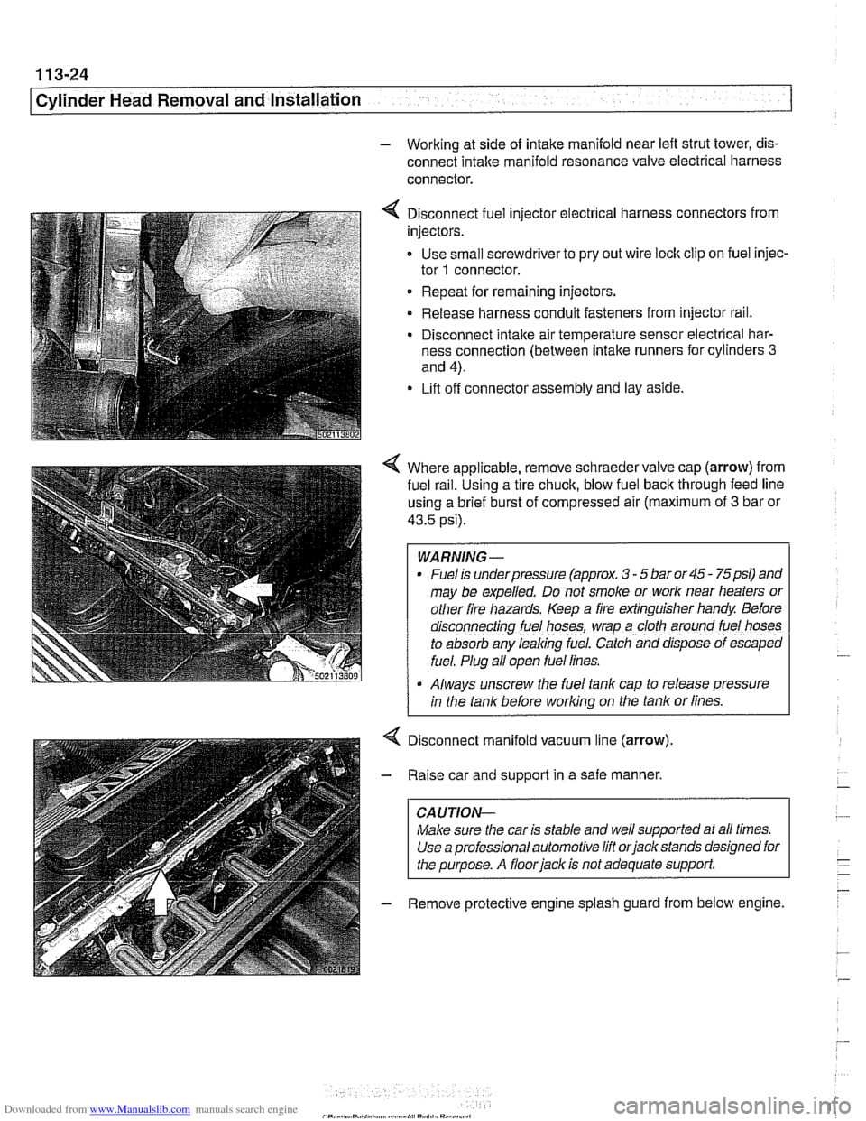
4 Disconnect fuel injector electrical harness connectors from
injectors.
- Use small screwdriver to pry out wire lock clip on fuel injec-
tor
1 connector.
Repeat for remaining injectors.
Release harness conduit fasteners from injector rail.
- Disconnect intake air temperature sensor electrical har-
ness connection (between intake runners for cylinders
3
and 4).
Lift off connector assembly and lay aside.
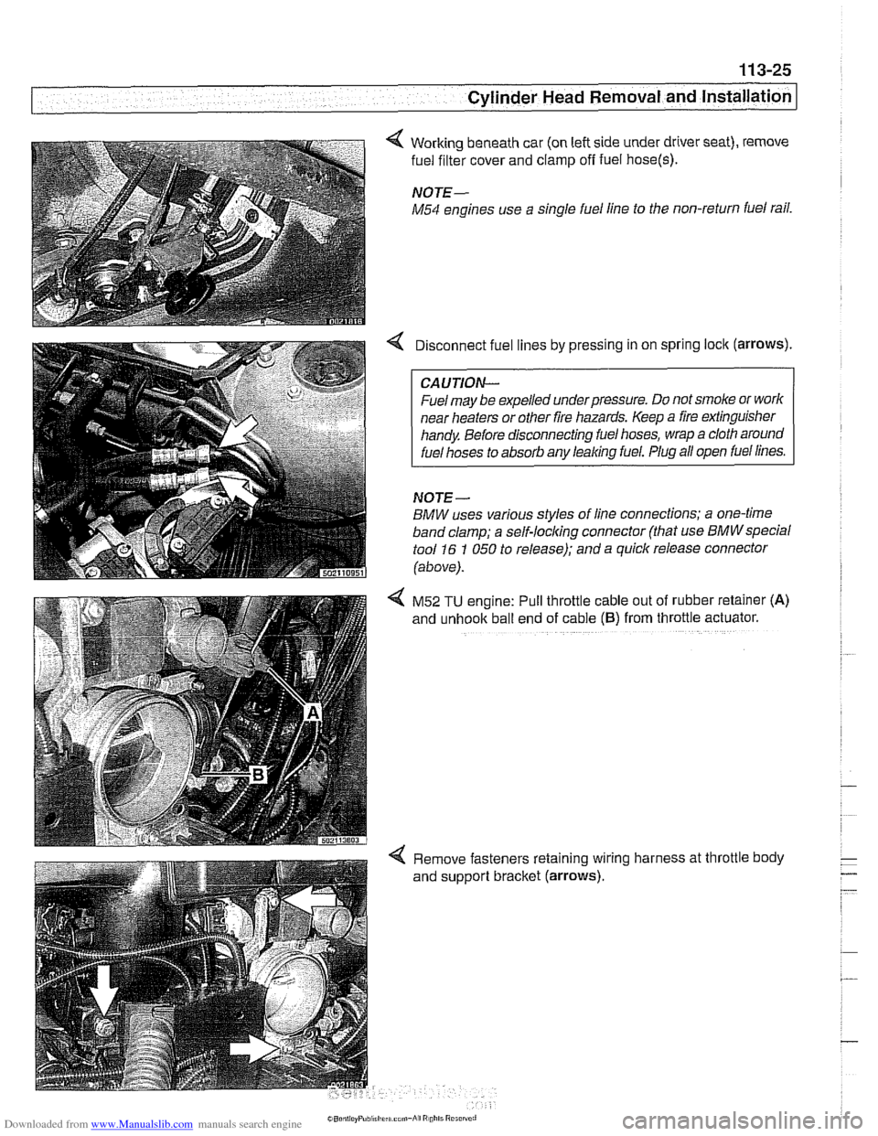
4 Where applicable, remove schraeder valve cap (arrow) from
fuel
ra~l. Using a tire chuck, blow fuel back through feed line
using a brief burst of compressed air (maximum of
3 bar or
43.5 psi).
WARNING-
Fuel is underpressure (approx. 3 - 5 bar or 45 - 75psi) and
may be expelled. Do not smoke or
work near heaters or
other fire hazards. Keep a fire extinguisher handy Before
d~sconnecting fuel hoses, wrap a cloth around fuel hoses
to absorb any leaking fuel. Catch and
dfspose of escaped
fuel. Plug all open fuel lines.
Always unscrew the fuel tank cap to release pressure
I in the tank before working on the tank or lines.
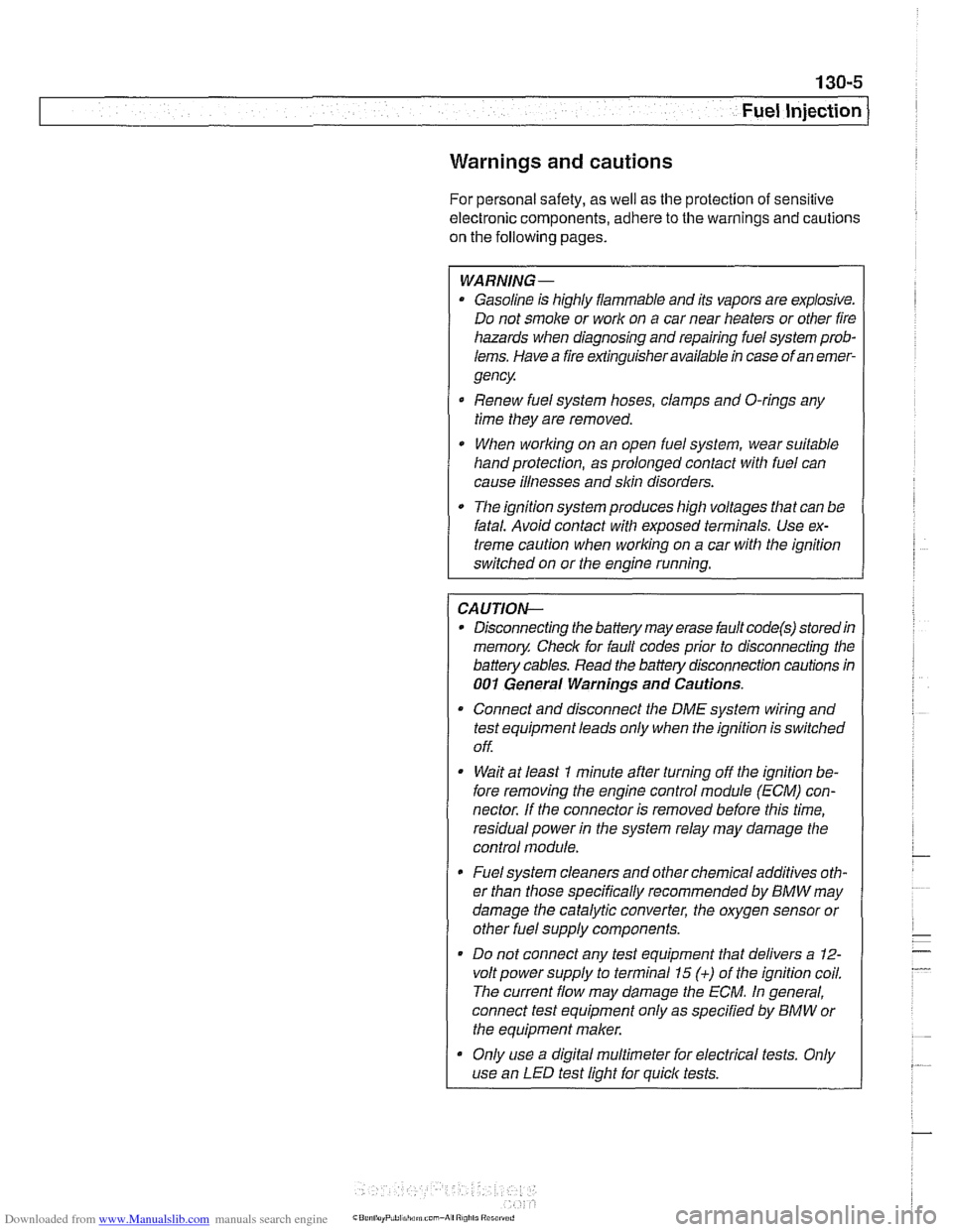
Disconnect manifold vacuum line (arrow)
Raise car and support in a safe manner,
CAUTION-
Make sure the car is stable and well supported at all times.
Use a professional automotive lift
orjack stands designed for
the purpose. A
floorjack is not adequate support.
Remove protective engine splash guard from below engine.
Page 119 of 1002

Downloaded from www.Manualslib.com manuals search engine
11 3-25
Cylinder Head Removal and Installation
4 Working beneath car (on left side under driver seat), remove
fuel filter cover and clamp
off fuel hose(s).
NOTE-
M54 engines use a single fuel line to the non-return fuel rail.
Disconnect fuel lines by pressing in on spring lock (arrows).
CAUTION--
Fuel may be expelled underpressure. Do not smoke or worlc
near heaters or other fire hazards. Keep a fire extinguisher
handy Before disconnecting fuel hoses, wrap a cloth around
fuel hoses to absorb any leaking fuel. Plug all open fuel lines.
NOJE-
BMW uses various styles of line connections; a one-time
band clamp; a
self-locl(ing connector (that use BMWspecial
tool 16 1 050 to release); and a quick release connector
(above).
4 M52 TU engine: Pull throttle cable out of rubber retainer (A)
and unhook ball end of cable (6) from throttle actuator.
4 Remove fasteners retaining wiring harness at throttle body
and support bracket (arrows).
Page 122 of 1002

Downloaded from www.Manualslib.com manuals search engine
I Cylinder Head Removal and Installation
4 Drain engine coolant and remove coolant hoses:
Remove expansion tank cap on radiator.
Place a
3 gallon pail beneath engine to capture coolant
Remove coolant drain plug (arrow) located on exhaust
side of cylinder
2 of engine block.
4 Drain radiator into a 3 gallon pail by removing plastic drain
plug (arrow) completely.
Use caution when draining and disposing of engine coolant.
Coolant is poisonous andlethal to humans andpets. Pets are
attracted to coolant because of its sweet smell and taste.
Seek medical
attention immediately if coolant is ingested.
NOTE-
Catch and dispose of drained coolant according to local,
state, and federal laws.
4 Remove thermostat housing:
. Disconnect electrical harness connector at thermostat
housing.
. Remove hoses from thermostat hous~ng by releasing loclts
(arrows).
Unbolt
(4 bolts) and remove thermostat hous~ng.
- On vehicles equipped with mechanical cooling fan: Remove
belt-driven cooling fan and radiator shroud as described in
170 Radiator and Cooling System.
CAUTIOI\C
32 mm radiator fan mounting nut has left hand threads. r
4 Remove fasteners (arrows) from heater bypass tube. Pull
tube out of cylinder head and set to side, leaving heater hose
connected.
- Unbolt power steering fluid reservoir and pull aside without
disconnecting hoses. Secure to fender with cord or stiff wire.
Page 154 of 1002

Downloaded from www.Manualslib.com manuals search engine
1 13-60
Cylinder Head Removal and Installation
Label and disconnect fuel lines from fuel rail by pressing lock-
ing sleeves
(arrows) in to release lines.
NOTE-
BMW uses three styles of fuel line connections; a single use
clamp; a locking fitting that uses special tool
16 1 050 to re-
lease; and a quick release sleeve
(arrow) that disconnects
the line when depressed.
CAUTION-
Fuel may be expelled under pressure. Do not smoke or
work near heaters or other fire hazards. Keep a fire
exfin-
guisher handy Before disconnecting fuel hoses, wrap a
cloth around fuel hoses to absorb
leaking fuel. Plug all
I ooen fuel lines. I
Always unscrew fuel tank cap to release pressure in
tank before
removinq fuel lines.
Cap fuel lines and fuel rail inlets.
Disconnect vacuum lines
(A, B and C) from rear of intake
manifold.
Working at rear of intake manifold, disconnect crankcase
ventilation valve from pipe by prying up on lock
(A) and slid-
ing tube forward
(B).
Page 395 of 1002

Downloaded from www.Manualslib.com manuals search engine
Fuel Injection
Warnings and cautions
For personal safety, as well as the protection of sensitive
electronic components, adhere to the warnings and cautions
on the following pages.
WARNING-
Gasoline is highly flammable and its vapors are explosive.
Do not smoke or work on a car near heaters or other fire
hazards when diagnosing and repairing fuel system prob-
lems. Have a fire extinguisher available in case of an emer-
gency
Renew fuel system hoses, clamps and O-rings any
time they are removed.
When working on an open fuel system, wear suitable
hand protection, as prolonged contact
with fuel can
cause illnesses and skin disorders.
* The ignition system produces high voltages that can be
fatal. Avoid contact with exposed terminals. Use ex-
treme caution when
working on a car with the ignition
switched on or the engine running.
CAUTION-
- Disconnecting the battery may erase fault code($ storedin
memory Check for fault codes prior to disconnecting the
battery cables. Read the battery disconnection cautions in
001 General Warnings and Cautions.
a Connect and disconnect the DME system wiring and
1 test equipment leads only when the ignition is switched
off.
Wait at least 1 minute after turning off the ignition be-
fore removing the engine control module (ECM) con-
nector. If the connector is removed before this time,
residualpower in the system relay may damage the
control module.
Fuel system cleaners and other chemical additives oth-
er than those specifically recommended by BMW may
damage the catalytic converter, the oxygen sensor or
other fuel supply components.
* Do not connect any test equipment that delivers a 12-
volt power supply to terminal 15 (+) of the ignition coil.
The current flow may damage the ECM. In general,
connect test equipment only as specified by BMW or
the equipment maker.
Only use a digital
multirneter for electrical tests. Only
use an LED test light for
quiclc tests.
Page 406 of 1002

Downloaded from www.Manualslib.com manuals search engine
I Fuel Injection
Release injector locking clips at each injector and pry injector
wiring duct up off injectors.
Clamp off fuel supply line and fuel return line at end of fuel
rail. Disconnect fuel supply fuel return lines from fuel rail.
WARNING -
Clamp off the fuel lines and then wrap a clean shop towel
around the lines before removing them. Residual
fuelpres-
sure is present in the lines.
Fuel is discharged. Do not disconnect any wires that
could cause electrical
sparks. Do not smoke or work
near heaters or other fire hazards. Keep an approved
I fire extinguisher handy. I
- Remove fuel rail mounting fasteners
- Pull up on fuel rail and remove individual injectors by remov-
ing injector retaining clip and pulling injector from rail.
- Installation is reverse of removal. Fit new O-rings when in-
stalling injectors. For ease of installation, lightly lubricate in-
jector O-ring with
SAE9O gear lube.
Tightening torque Fuel rail to
intake manifold 10 Nm (89 in-lb)
Evaporative emissions, overview
On E39 MS 41 .I cars, the evaporative emissions system is
combined with the tank ventilation system. The evaporative
system is monitored by the ECM for correct purge operation
and leak detection.
The carbon (purge) canister is purged using engine vacuum
via the
purgevalve.The purgevalve (located nextto the mass
airflow sensor) is ECM controlled and regulates the purge
flow into the intake manifold. The valve is powered open and
closed by an internal spring.
If the evaporative emission valve circuit is faulty, a fault code
is set and the MIL is illuminated when OBD
II fault criteria are
exceeded. If the valve is mechanically faulty, poor driveability
may result and a mixture adaptation fault is stored in the
ECM.
The leak diagnosis pump (LDP) is activated by the ECM and
pressurizes the fuel tank and evaporative system as apart of
theOED I1 leakdetection monitor. If the LDP orthe LDP circuit
is defective, afault code is set and the MIL is illuminated when
OBD
I1 fault criteria are exceeded. The LDP is mounted the
left rear wheel well behind the fender liner.
Page 410 of 1002

Downloaded from www.Manualslib.com manuals search engine
I Fuel Injection
Table b. Siemens MS 41.1 ECM pin assignments (continued)
Pin
l~iqnal I Componentlfunction 1 Notes I - I I
5 loutput I Fuel injector control, cyl. 2 I Pulsed ground (pulse width in ms), cyl. 2 I I I
6 loutput /Fuel injector control, cyi. 1 I Pulsed ground (pulse width in ms), cyl. 1
I I I
14 linput I Intake air temp. sensor (IAT) I Intake air temperature signal
- 7
8
9
10
11
12
13
ground
input
output
input
input
15
16
17 18
19
20
21
22
I - I I
35 loutput /Secondary air injection ISecondary air inj. pump relay control
25
26
27
28
29
30
31
32
33
36
/output I Engine speed output IEngine speed signal
Mass air flow sensor
Mass air flow sensor
instrument cluster
Engine coolant
temp.
(ECT) sensor
Not used
Throttle position sensor (TPS)
Not used
input
input
input
input
output
output
out~ut
37 1 - /Not used I
Mass air flow sensor signal
Mass air flow sensor signal
Fuel consumption signal
ECT signal
Throttle position signal
ground
input
output
ground
output
output
output
ground
output
Traction control (rear engine speed signal) Automatic climate control
Not used Electronic immobilizer control (EWS)
Auto. climate control
(AIC on input)
instrument
cluster
Camshaft actuator control (VANOS)
Fuel iniector control, cvl.
3
AES/ASC module
Automatic climate control instrument cluster (CARE signal)
Camshaft actuator (VANOS), switched ground
Pulsed ground (pulse width in
ms), cyl. 3
Oxygen sensor heater (no. 1 in front of catalytic
converter)
Power supply (terminal
30)
Idle speed control valve
Ground
Ignition coil control, cyl.
1
Ignition coil control, cyl. 3
Ignition coil control, cyl. 5
Ground Fuel injector control, cyl.
5
Oxygen sensor heater ground
Battery voltage
(E+) at all times
Pulsed ground-open signal (See pin
53)
Ground
Primary signal, ignition coil
1
Primary signal, ignition coil 3
Primary signal, ignition coil 5
Ground
Pulsed ground (pulse width in ms), cyl
5