Page 25 of 51
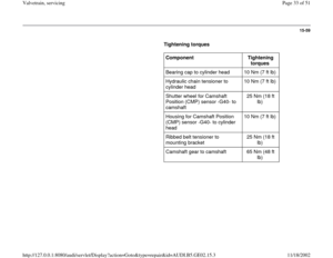
15-51
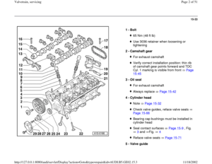
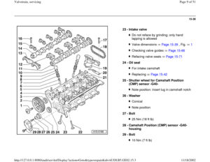
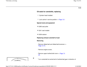
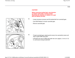
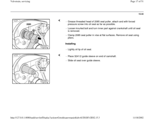
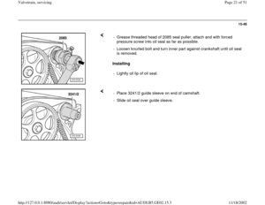
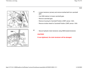
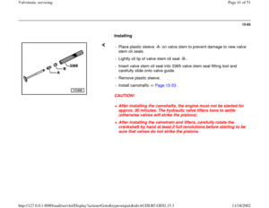
- Loosen tensioner (arrows) and remove toothed belt from camshaft
gear.
- Use 3036 retainer to loosen camshaft gear.
- Remove camshaft gear.
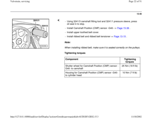
- Remove housing for Camshaft Position (CMP) sensor -G40-.
- Remove shutter wheel for Camshaft Position (CMP) sensor -G40-.
CAUTION!
If over-tightened, the chain tensioner will be damaged. - Secure hydraulic chain tensioner using 3366 bracket-tensioner.
Pa
ge 25 of 51 Valvetrain, servicin
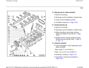
g
11/18/2002 htt
p://127.0.0.1:8080/audi/servlet/Dis
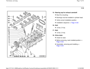
play?action=Goto&t
yp
e=re
pair&id=AUDI.B5.GE02.15.3
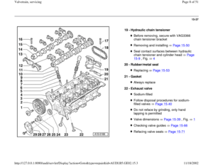
Page 26 of 51
15-52
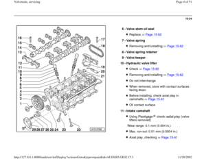
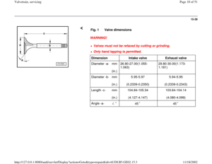
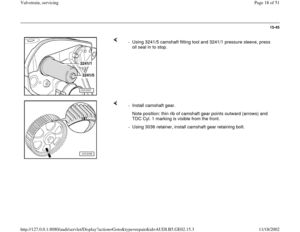
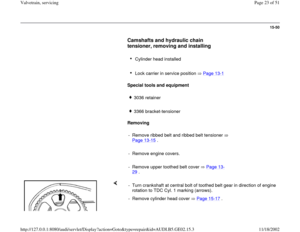
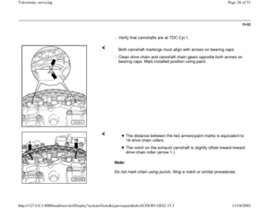
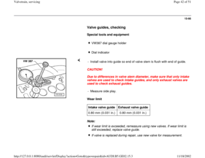
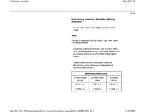
- Verify that camshafts are at TDC Cyl 1.
Both camshaft markings must align with arrows on bearing caps.
- Clean drive chain and camshaft chain gears opposite both arrows on
bearing caps. Mark installed position using paint.
Note:
Do not mark chain using punch, filing a notch or similar procedures.
The distance between the two arrows/paint marks is equivalent to
16 drive chain rollers.
The notch on the exhaust camshaft is slightly offset inward toward
drive chain roller (arrow-1-).
Pa
ge 26 of 51 Valvetrain, servicin
g
11/18/2002 htt
p://127.0.0.1:8080/audi/servlet/Dis
play?action=Goto&t
yp
e=re
pair&id=AUDI.B5.GE02.15.3
Page 27 of 51
15-53
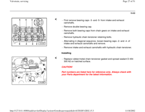
Installing - First remove bearing caps -3- and -5- from intake and exhaust
camshafts.
- Remove double bearing cap.
- Remove both bearing caps from chain gears on intake and exhaust
camshafts.
- Remove hydraulic chain tensioner retaining bolts.
- Alternating in diagonal sequence, loosen bearing caps -2- and -4- of
intake and exhaust camshafts and remove.
- Remove intake and exhaust camshafts with hydraulic chain tensioner.
CAUTION!
Part numbers are listed here for reference only. Always check with
your Parts department for the latest information. - Replace rubber/metal chain tensioner gasket and spread sealant D 454
300 A2 on hatched surface.
Pa
ge 27 of 51 Valvetrain, servicin
g
11/18/2002 htt
p://127.0.0.1:8080/audi/servlet/Dis
play?action=Goto&t
yp
e=re
pair&id=AUDI.B5.GE02.15.3
Page 28 of 51
15-54
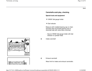
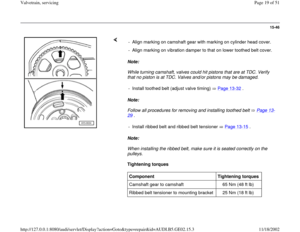
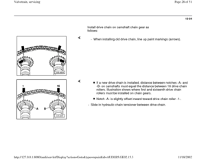
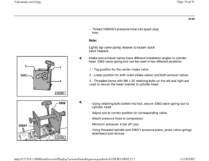
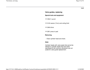
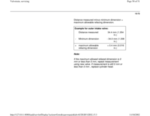
Install drive chain on camshaft chain gear as
follows:
- When installing old drive chain, line up paint markings (arrows).
If a new drive chain is installed, distance between notches -A- and
-B- on camshafts must equal the distance between 16 drive chain
rollers. Illustration shows where first and sixteenth drive chain
rollers must be installed on chain gears.
Notch -A- is slightly offset inward toward drive chain roller -1-.
- Slide in hydraulic chain tensioner between drive chain.
Pa
ge 28 of 51 Valvetrain, servicin
g
11/18/2002 htt
p://127.0.0.1:8080/audi/servlet/Dis
play?action=Goto&t
yp
e=re
pair&id=AUDI.B5.GE02.15.3
Page 29 of 51
15-55
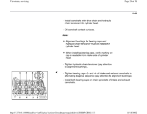
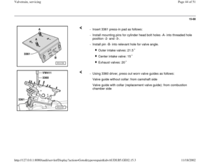
- Install camshafts with drive chain and hydraulic
chain tensioner into cylinder head.
- Oil camshaft contact surfaces.
Note:
Alignment bushings for bearing caps and
hydraulic chain tensioner must be installed in
cylinder head.
When installing bearing caps, verify marking on
cap is readable from intake side of cylinder
head.
- Tighten hydraulic chain tensioner (pay attention
to alignment bushings).
- Tighten bearing caps -2- and -4- of intake and exhaust camshafts in
alternating diagonal sequence (pay attention to alignment bushings).
- Install both bearing caps on chain sprockets of intake and exhaust
camshafts.
Pa
ge 29 of 51 Valvetrain, servicin
g
11/18/2002 htt
p://127.0.0.1:8080/audi/servlet/Dis
play?action=Goto&t
yp
e=re
pair&id=AUDI.B5.GE02.15.3
Page 30 of 51
15-56
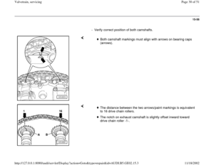
- Verify correct position of both camshafts.
Both camshaft markings must align with arrows on bearing caps
(arrows).
The distance between the two arrows/paint markings is equivalent
to 16 drive chain rollers.
The notch on exhaust camshaft is slightly offset inward toward
drive chain roller -1-.
Pa
ge 30 of 51 Valvetrain, servicin
g
11/18/2002 htt
p://127.0.0.1:8080/audi/servlet/Dis
play?action=Goto&t
yp
e=re
pair&id=AUDI.B5.GE02.15.3
Page 31 of 51
15-57
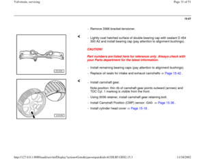
- Remove 3366 bracket-tensioner.
CAUTION!
Part numbers are listed here for reference only. Always check with
your Parts department for the latest information. - Lightly coat hatched surface of double bearing cap with sealant D 454
300 A2 and install bearing cap (pay attention to alignment bushings).
- Install remaining bearing caps (pay attention to alignment bushings).
- Replace oil seals for intake and exhaust camshafts Page 15
-42
.
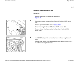
- Install camshaft gear.
Note position: thin rib of camshaft gear points outward (arrows) and
TDC Cyl. 1 marking is visible from the front.
- Using 3036 retainer, install camshaft gear retaining bolt.
- Install Camshaft Position (CMP) sensor -G40- Page 15
-38
.
- Install cylinder head cover Page 15
-18
.
Pa
ge 31 of 51 Valvetrain, servicin
g
11/18/2002 htt
p://127.0.0.1:8080/audi/servlet/Dis
play?action=Goto&t
yp
e=re
pair&id=AUDI.B5.GE02.15.3
Page 32 of 51

15-58
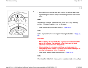
Note:
When turning camshaft, crankshaft must not be at TDC Cyl. 1 for any
cylinder. Valves and/or pistons may be damaged.
Note:
Follow all procedures for removing and installing toothed belt Page 13
-
29
.
CAUTION!
Note:
When installing ribbed belt, make sure it is seated correctly on the pulleys. - Align marking on camshaft gear with marking on cylinder head cover.
- Align marking on vibration damper with marking on lower toothed belt
cover.
- Install toothed belt (adjust valve timing) Page 13
-32
.
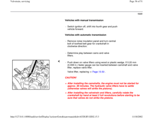
After installing the camshafts, the engine must not be started for
approx. 30 minutes. The hydraulic valve lifters have to settle
(otherwise valves will strike the pistons). After installing the valvetrain and lifters, carefully rotate the
crankshaft by hand at least 2 full revolutions before starting to be
sure that valves do not strike the pistons.
- Install ribbed belt and ribbed belt tensioner Page 13
-15
.
Pa
ge 32 of 51 Valvetrain, servicin
g
11/18/2002 htt
p://127.0.0.1:8080/audi/servlet/Dis
play?action=Goto&t
yp
e=re
pair&id=AUDI.B5.GE02.15.3
 and remove toothed belt from camshaft
gear.
- Use 3036 retainer to loosen camshaft gear.
- Remove camshaft gear.
- Remove housing for Camshaft Position (")


.
If a new drive chain is installed, distance be")

.
The distance between the two arrows/paint markings is")
