Page 26 of 44

01-126
Carrying out "Output Diagnostic Test Mode"
function 03
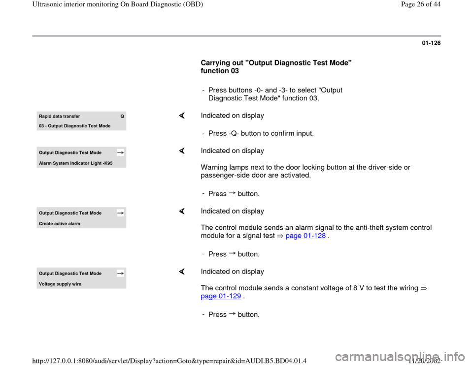
- Press buttons -0- and -3- to select "Output
Diagnostic Test Mode" function 03. Rapid data transfer
Q
03 - Output Dia
gnostic Test Mode
Indicated on display
- Press -Q- button to confirm input.
Output Diagnostic Test Mode Alarm S
ystem Indicator Li
ght -K95
Indicated on display
Warning lamps next to the door locking button at the driver-side or
passenger-side door are activated.
-
Press button.
Output Diagnostic Test Mode Create active alarm
Indicated on display
The control module sends an alarm signal to the anti-theft system control
module for a signal test page 01
-128
.
-
Press button.
Output Diagnostic Test Mode Volta
ge suppl
y wire
Indicated on display
The control module sends a constant voltage of 8 V to test the wiring
page 01
-129
.
-
Press button.
Pa
ge 26 of 44 Ultrasonic interior monitorin
g On Board Dia
gnostic
(OBD
)
11/20/2002 htt
p://127.0.0.1:8080/audi/servlet/Dis
play?action=Goto&t
yp
e=re
pair&id=AUDI.B5.BD04.01.4
Page 27 of 44
01-127
Output Diagnostic Test Mode Wire for c
ycle si
gnal
Indicated on display
The control module sends a constant voltage of 5 V to test the wiring
page 01
-130
.
-
Press button.
Output Diagnostic Test Mode END
Indicated on display
The program is now back at its starting point. -
Press button.
Rapid data transfer
HELP
Select function XX
Indicated on display
Pa
ge 27 of 44 Ultrasonic interior monitorin
g On Board Dia
gnostic
(OBD
)
11/20/2002 htt
p://127.0.0.1:8080/audi/servlet/Dis
play?action=Goto&t
yp
e=re
pair&id=AUDI.B5.BD04.01.4
Page 30 of 44
01-129
- Shut off alarm by unlocking vehicle.
- End Output Diagnostic Test Mode (DTM).
- Initiate On Board Diagnostic (OBD) for anti-theft
system.
- Erase DTC memory page 01
-137
.
Checking power supply wiring
- Remove both ultra-sound sensors.
Repair Manual, Body Interior, Repair Group
70, B
-pillar trim , removing and installing
- Disconnect electronic harness connectors.
- Perform Output Diagnostic Test Mode ( page
01
-124
) and select output test "Power supply
wiring."
Output Diagnostic Test Mode Power suppl
y wirin
g
Indicated on display
- Using multimeter (Fluke 83 or equivalent), measure voltage at wiring
harness connector between terminal 2 (B+) and terminal 3 (GND).
Pa
ge 30 of 44 Ultrasonic interior monitorin
g On Board Dia
gnostic
(OBD
)
11/20/2002 htt
p://127.0.0.1:8080/audi/servlet/Dis
play?action=Goto&t
yp
e=re
pair&id=AUDI.B5.BD04.01.4
Page 32 of 44
01-130
Checking wiring for pulse signal
- Remove both ultra-sound sensors.
Repair Manual, Body Interior, Repair Group
70, B
-pillar trim , removing and installing
- Disconnect electronic harness connectors.
- Perform Output Diagnostic Test Mode (DTM) (
page 01
-124
) and select control element test
"Signal pulse wire."
Output Diagnostic Test Mode Signal pulse wire
Indicated on display
- Using multimeter (Fluke 83 or equivalent), measure voltage at wiring
harness connector between terminal 1 (pulse signal) and terminal 3
(GND).
Specification: 5 V
- End Output Diagnostic Test Mode (DTM).
- Re-install ultra-sound sensors.
- Erase DTC memory (function 05) page 01
-137
.
- End Output (function 06) page 01
-139
.
Pa
ge 32 of 44 Ultrasonic interior monitorin
g On Board Dia
gnostic
(OBD
)
11/20/2002 htt
p://127.0.0.1:8080/audi/servlet/Dis
play?action=Goto&t
yp
e=re
pair&id=AUDI.B5.BD04.01.4