Page 9 of 19
50-9
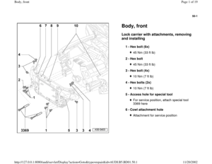
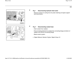
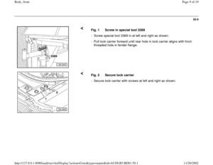
Fig. 1 Screw in special tool 3369
- Screw special tool 3369 in at left and right as shown.
- Pull lock carrier forward until rear hole in lock carrier aligns with front
threaded hole in fender flange.
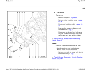
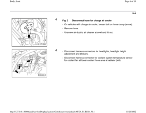
Fig. 2 Secure lock carrier
- Secure lock carrier with screws at left and right as shown.
Pa
ge 9 of 19 Bod
y, front
11/20/2002 htt
p://127.0.0.1:8080/audi/servlet/Dis
play?action=Goto&t
yp
e=re
pair&id=AUDI.B5.BD01.50.1
Page 10 of 19
50-10
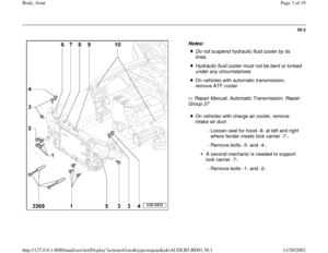
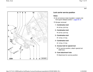
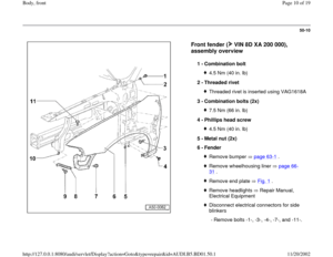
Front fender ( VIN 8D XA 200 000),
assembly overview
1 -
Combination bolt
4.5 Nm (40 in. lb)
2 -
Threaded rivet Threaded rivet is inserted using VAG1618A
3 -
Combination bolts (2x) 7.5 Nm (66 in. lb)
4 -
Phillips head screw 4.5 Nm (40 in. lb)
5 -
Metal nut (2x)
6 -
Fender Remove bumper page 63
-1 .
Remove wheelhousing liner page 66
-
31
.
Remove end plate Fig. 1
.
Remove headlights Repair Manual,
Electrical Equipment Disconnect electrical connectors for side
blinkers
- Remove bolts -1-, -3-, -4-, -7-, and -11-.
Pa
ge 10 of 19 Bod
y, front
11/20/2002 htt
p://127.0.0.1:8080/audi/servlet/Dis
play?action=Goto&t
yp
e=re
pair&id=AUDI.B5.BD01.50.1
Page 11 of 19
50-11
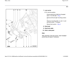
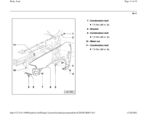
7 -
Combination bolt
7.5 Nm (66 in. lb)
8 -
Bracket
9 -
Combination bolt 7.5 Nm (66 in. lb)
10 -
Metal nut
11 -
Combination bolt 7.5 Nm (66 in. lb)
Pa
ge 11 of 19 Bod
y, front
11/20/2002 htt
p://127.0.0.1:8080/audi/servlet/Dis
play?action=Goto&t
yp
e=re
pair&id=AUDI.B5.BD01.50.1
Page 12 of 19
50-12
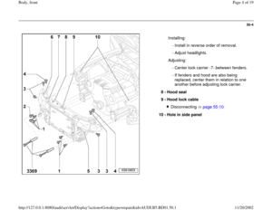
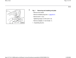
Fig. 1 Removing and installing end plate
- Remove front wheel.
- Remove wheelhousing liner page 66
-31
.
- Remove bolt -2- (2x).
Tightening torque: 2.5 Nm (22 in. lb)
- Remove endplate -3- from fender -4-.
1 - Expanding clip (2x)
Pa
ge 12 of 19 Bod
y, front
11/20/2002 htt
p://127.0.0.1:8080/audi/servlet/Dis
play?action=Goto&t
yp
e=re
pair&id=AUDI.B5.BD01.50.1
Page 13 of 19
50-13
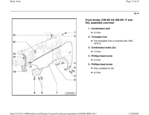
Front fender (VIN 8D XA 200 001 and
S4), assembly overview
1 -
Combination bolt
4.5 Nm
2 -
Threaded rivet The threaded rivet is inserted with VAG
1618 A.
3 -
Combination bolts (2x) 7.5 Nm
4 -
Phillips-head screw 4.5 Nm
5 -
Phillips-head screw Only installed for S4.4.5 Nm
Pa
ge 13 of 19 Bod
y, front
11/20/2002 htt
p://127.0.0.1:8080/audi/servlet/Dis
play?action=Goto&t
yp
e=re
pair&id=AUDI.B5.BD01.50.1
Page 14 of 19
50-14
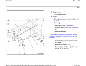
Repair Manual, Electrical Equipment, Repair
Group 94, headlights, headlights, removing and installing.
6 -
Snap-on nut Only installed for S4.
7 -
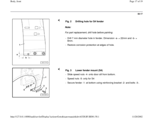
Fender Drill additional hole at bottom for S4 fender
Fig. 2
.
Removing:
- Remove bumper page 63
-5 .
- Remove wheelhousing liner page 66
-
31
.
- Remove headlights - Disconnect harness connector for side
turn-signal.
- Remove end plate Fig. 1
.
- Remove bolts -1-; -3-; -4- (bolt -5- only
for S4) -8-; -9- and -14-.
Pa
ge 14 of 19 Bod
y, front
11/20/2002 htt
p://127.0.0.1:8080/audi/servlet/Dis
play?action=Goto&t
yp
e=re
pair&id=AUDI.B5.BD01.50.1
Page 15 of 19
50-15
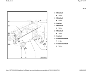
8 -
Metal bolt
7.5 Nm
9 -
Metal bolt 7.5 Nm
10 -
Bracket
11 -
Metal bolt 7.5 Nm
12 -
Metal bolt 7.5 Nm
13 -
Bracket
14 -
Combination bolt 10 Nm
15 -
Combination bolt 7.5 Nm
Pa
ge 15 of 19 Bod
y, front
11/20/2002 htt
p://127.0.0.1:8080/audi/servlet/Dis
play?action=Goto&t
yp
e=re
pair&id=AUDI.B5.BD01.50.1
Page 16 of 19
50-16
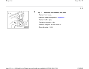
Fig. 1 Removing and installing end plate
- Remove front wheel.
- Remove wheelhousing liner page 66
-31
.
- Remove bolt -2- (2x).
Tightening torque: 2.5 Nm
- Remove end plate -3- from fender -4-.
- Expanding clip -1- (2x).
Pa
ge 16 of 19 Bod
y, front
11/20/2002 htt
p://127.0.0.1:8080/audi/servlet/Dis
play?action=Goto&t
yp
e=re
pair&id=AUDI.B5.BD01.50.1

,
assembly overview
1 -
Combination bolt
4.5 Nm (40 in. lb)
2 -
Threaded rivet Threaded rivet is inserted using VAG1618A
3 -
Combination bolts (2x)")

8 -
Bracket
9 -
Combination bolt 7.5 Nm (66 in. lb)
10 -
Metal nut
11 -
Combination bolt 7.5 Nm (66 in. lb)
Pa
ge 11 of 19 Bod
y, front
11/20")
.
Tightening torque: 2.5 Nm (22 in. lb)
- Remove")
, assembly overview
1 -
Combination bolt
4.5 Nm
2 -
Threaded rivet The threaded rivet is inserted with VAG
1618 A.
3 -
Combination bolts (2")


.
Tightening torque: 2.5 Nm
- Remove end plate")