Page 17 of 41
26-17
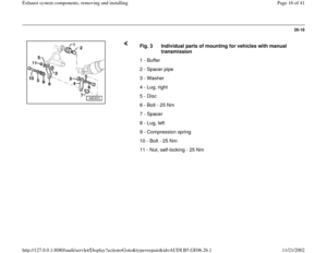
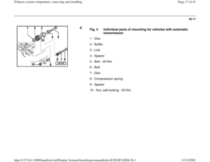
Fig. 4 Individual parts of mounting for vehicles with automatic
transmission
1 - Disc
2 - Buffer
3 - Link
4 - Spacer
5 - Bolt - 25 Nm
6 - Bolt
7 - Disc
8 - Compression spring
9 - Spacer
10 - Nut, self-locking - 25 Nm
Pa
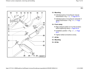
ge 17 of 41 Exhaust s
ystem com
ponents, removin
g and installin
g
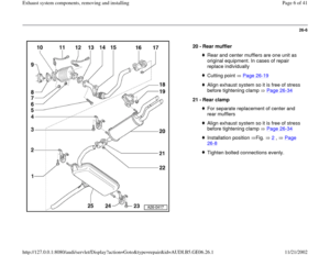
11/21/2002 htt
p://127.0.0.1:8080/audi/servlet/Dis
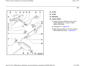
play?action=Goto&t
yp
e=re
pair&id=AUDI.B5.GE06.26.1
Page 18 of 41
26-18
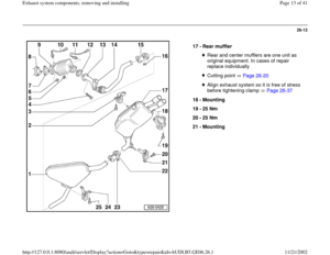
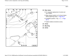
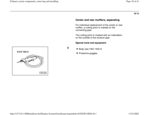
Center and rear mufflers, separating
For individual replacement of the center or rear
muffler, a cutting point is marked on the
connecting pipe.
The cutting point is marked with an indentation
on the outside of the exhaust pipe.
Special tools and equipment
Body saw VAG 1523 AProtective goggles
Pa
ge 18 of 41 Exhaust s
ystem com
ponents, removin
g and installin
g
11/21/2002 htt
p://127.0.0.1:8080/audi/servlet/Dis
play?action=Goto&t
yp
e=re
pair&id=AUDI.B5.GE06.26.1
Page 19 of 41
26-19
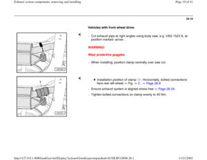
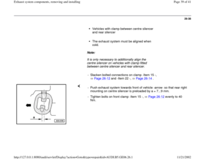
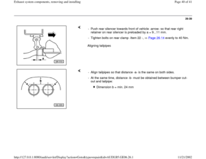
Vehicles with front wheel drive:
WARNING!
Wear protective goggles. - Cut exhaust pipe at right angles using body saw, e.g. VAG 1523 A, at
position marked -arrow-.
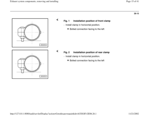
- When installing, position clamp centrally over saw cut.
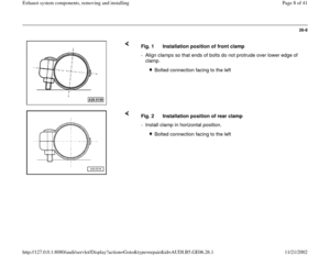
Installation position of clamp -1-: Horizontally, bolted connections
face rear left wheel Fig. 2
, Page 26
-8
- Ensure exhaust system is aligned stress-free Page 26
-34
.
- Tighten bolted connections on clamp evenly to 40 Nm.
Pa
ge 19 of 41 Exhaust s
ystem com
ponents, removin
g and installin
g
11/21/2002 htt
p://127.0.0.1:8080/audi/servlet/Dis
play?action=Goto&t
yp
e=re
pair&id=AUDI.B5.GE06.26.1
Page 20 of 41
26-20
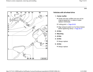
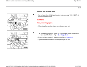
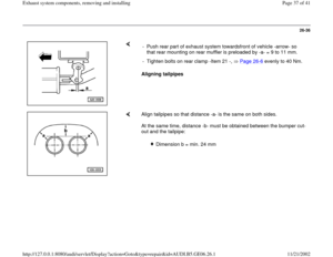
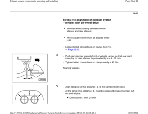
Vehicles with all-wheel drive:
WARNING!
Wear protective goggles. - Cut exhaust pipe at right angles using body saw, e.g. VAG 1523 A, at
position marked -arrow-.
- When installing, position clamp centrally over saw cut.
Installation position of clamp -1-: Horizontally, bolted connections
face rear left wheel Fig. 2
, Page 26
-15
- Ensure exhaust system is aligned stress-free Page 26
-37
.
- Tighten bolted connections on clamp evenly to 40 Nm.
Pa
ge 20 of 41 Exhaust s
ystem com
ponents, removin
g and installin
g
11/21/2002 htt
p://127.0.0.1:8080/audi/servlet/Dis
play?action=Goto&t
yp
e=re
pair&id=AUDI.B5.GE06.26.1
Page 21 of 41
26-21
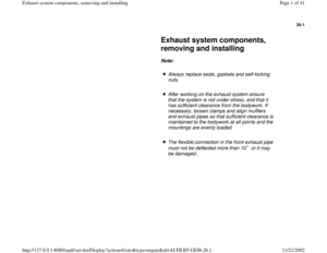
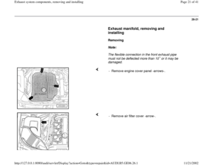
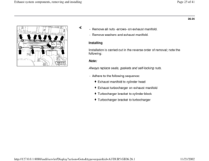
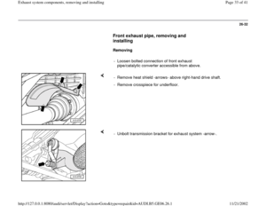
Exhaust manifold, removing and
installing
Removing
Note:
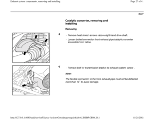
The flexible connection in the front exhaust pipe
must not be deflected more than 10 or it may be
damaged.
- Remove engine cover panel -arrows-.
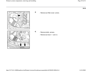
- Remove air filter cover -arrow-.
Pa
ge 21 of 41 Exhaust s
ystem com
ponents, removin
g and installin
g
11/21/2002 htt
p://127.0.0.1:8080/audi/servlet/Dis
play?action=Goto&t
yp
e=re
pair&id=AUDI.B5.GE06.26.1
Page 22 of 41
26-22
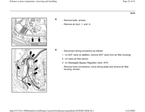
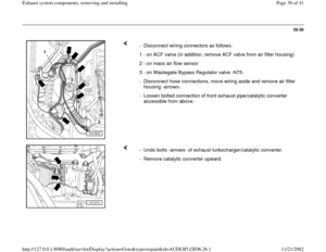
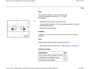
- Remove bolts -arrows-.
- Remove air duct -1- and -2-.
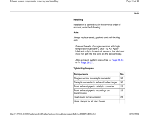
- Disconnect wiring connectors as follows:
1 - on ACF valve (in addition, remove ACF valve from air filter housing)
2 - on mass air flow sensor
3 - on Wastegate Bypass Regulator valve -N75-
- Remove hose connections, move wiring aside and remove air filter
housing -arrows-.
Pa
ge 22 of 41 Exhaust s
ystem com
ponents, removin
g and installin
g
11/21/2002 htt
p://127.0.0.1:8080/audi/servlet/Dis
play?action=Goto&t
yp
e=re
pair&id=AUDI.B5.GE06.26.1
Page 23 of 41
26-23
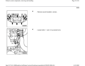
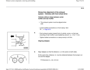
- Remove sound insulation -arrows-.
- Loosen bolts -1- and -2- by several turns.
Pa
ge 23 of 41 Exhaust s
ystem com
ponents, removin
g and installin
g
11/21/2002 htt
p://127.0.0.1:8080/audi/servlet/Dis
play?action=Goto&t
yp
e=re
pair&id=AUDI.B5.GE06.26.1
Page 24 of 41
26-24
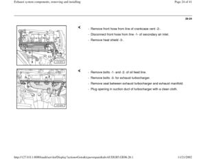
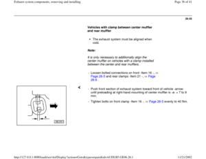
- Remove front hose from line of crankcase vent -2-.
- Disconnect front hose from line -1- of secondary air inlet.
- Remove heat shield -3-.
- Remove bolts -1- and -2- of oil feed line.
- Remove bolts -3- for exhaust turbocharger.
- Remove seal between exhaust turbocharger and exhaust manifold.
- Plug opening in suction duct of turbocharger with a clean cloth.
Pa
ge 24 of 41 Exhaust s
ystem com
ponents, removin
g and installin
g
11/21/2002 htt
p://127.0.0.1:8080/audi/servlet/Dis
play?action=Goto&t
yp
e=re
pair&id=AUDI.B5.GE06.26.1


2 - on")

