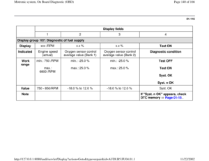
Page 89 of 166

01-73
DTC
Description of malfunction
Corrective action
SAE
VAG
P1650 18058 Powertrain CAN-bus
Missing message from instrument
cluster - Check data transfer Page 24-201
P1654 18062 Check DTC memory of the instrument
cluster - Check DTC memory of instrument cluster and repair
malfunctions
P1676 18084 Drive by Wire-MIL Circ.
Electrical Malfunction
1) - Significance of Electronic Power Control (EPC) warning light
Page 24
-142
P1677 18085 Drive by Wire-MIL Circ.
Short to B+
1)
P1690 18098 Malfunction Indication Light
Malfunction 2) - Check wiring for exhaust Malfunction Indicator Light (MIL)
Page 01
-4
P1693 18101 Malfunction Indication Light
Short circuit to B+
2)
1) With this malfunction the EPC (Electronic Power Control) Malfunction Indicator Light (MIL) in the instrument cluster is
switched on by the ECM. Significance of EPC malfunction indicator light Page 24
-142
.
2) With this malfunction the exhaust Malfunction Indicator Light (MIL) is only switched on by the ECM, if the malfunction is
recognized after the engine has been restarted. Significance of MIL Page 01
-3 .
Pa
ge 89 of 166 Motronic s
ystem, On Board Dia
gnostic
(OBD
)
11/22/2002 htt
p://127.0.0.1:8080/audi/servlet/Dis
play?action=Goto&t
yp
e=re
pair&id=AUDI.B5.FU04.01.1
Page 90 of 166
Note:
The malfunction light for power acceleration -K132- is also called the EPC warning lamp.
Pa
ge 90 of 166 Motronic s
ystem, On Board Dia
gnostic
(OBD
)
11/22/2002 htt
p://127.0.0.1:8080/audi/servlet/Dis
play?action=Goto&t
yp
e=re
pair&id=AUDI.B5.FU04.01.1
Page 91 of 166

01-74
DTC
Description of malfunction
Corrective action
SAE
VAG
P1851 18259 Data Bus Powertrain
Missing Message from Brake Contr
Repair Manual, Brake System On Board Diagnostic (OBD), Repair
Group 01, checking DTC memory of ABS control module
- Check DTC memory of ABS control module
- Check data exchange between Engine-/ABS-
/Transmission control
module Page 24
-201
P1853 18261 Data Bus Powertrain
Unplausible Message from Brake
Contr.
P1854 18262 Data Bus Powertrain
Hardware Defective
P3262 19718 Exhaust bank 1/2 oxygen sensors
behind catalytic converter
mixed up - Check harness connectors for oxygen sensors and check installed
position of oxygen sensors behind catalytic converter. 1) With this malfunction the EPC (Electronic Power Control) Malfunction Indicator Light (MIL) in the instrument cluster is
switched on by the ECM. Significance of EPC malfunction indicator light Page 24
-142
.
2) With this malfunction the exhaust Malfunction Indicator Light (MIL) is only switched on by the ECM, if the malfunction is
recognized after the engine has been restarted. Significance of MIL Page 01
-3 .
Pa
ge 91 of 166 Motronic s
ystem, On Board Dia
gnostic
(OBD
)
11/22/2002 htt
p://127.0.0.1:8080/audi/servlet/Dis
play?action=Goto&t
yp
e=re
pair&id=AUDI.B5.FU04.01.1
Page 92 of 166
01-75
Output Diagnostic Test Mode (DTM)
Notes:
The DTM can only be performed with the
ignition switched on and the engine not running.
The DTM is terminated if the engine is started
or if an engine speed pulse is detected.
During the DTM, individual control elements will
be activated for approx. 1 minute, or until the
test program is advanced to the next control
element by pressing the button.
The control elements can be tested either by
listening or by touching.
If the DTM is to be repeated, the engine must
be started. The engine control module needs to
detect an engine speed of more than 300 rpm.
The electric fuel pump runs continuously
throughout the DTM.
Pa
ge 92 of 166 Motronic s
ystem, On Board Dia
gnostic
(OBD
)
11/22/2002 htt
p://127.0.0.1:8080/audi/servlet/Dis
play?action=Goto&t
yp
e=re
pair&id=AUDI.B5.FU04.01.1
Page 93 of 166
01-76
The DTM activates the following components
in the stated sequence:
Activation sequence
1. EVAP Canister Purge Regulator Valve -
N80-
2. Secondary Air Injection (AIR) Solenoid
Valve -N112-
(This display appears only on vehicles with
automatic transmission)
3. Secondary Air Injection (AIR) Pump Relay -
J299-
(This display appears only on vehicles with
automatic transmission)
4. Wastegate Bypass Regulator Valve -N75
5. Camshaft adjustment
6. Leak Detection Pump for EVAP system
7. Recirculating valve for turbocharger -N249
8. Cylinder 1 Fuel Injector -N30
9. Cylinder 4 Fuel Injector -N33
10. Cylinder 3 Fuel Injector -N32
11. Cylinder 6 Fuel Injector -N84
12. Cylinder 2 Fuel Injector -N31
Pa
ge 93 of 166 Motronic s
ystem, On Board Dia
gnostic
(OBD
)
11/22/2002 htt
p://127.0.0.1:8080/audi/servlet/Dis
play?action=Goto&t
yp
e=re
pair&id=AUDI.B5.FU04.01.1
Page 94 of 166
13. Cylinder 5 Fuel Injector -N83
Pa
ge 94 of 166 Motronic s
ystem, On Board Dia
gnostic
(OBD
)
11/22/2002 htt
p://127.0.0.1:8080/audi/servlet/Dis
play?action=Goto&t
yp
e=re
pair&id=AUDI.B5.FU04.01.1
Page 95 of 166
01-77
Test requirements
Fuses for engine electronics OK
Fuel pump relay OK
- Connect vehicle diagnostic, testing and
information system VAS 5051 or VAG1551 scan
tool and select engine electronics control
module by entering address word "01" Page 01
-9 . When doing this the ignition must be
switched on.
Rapid data transfer
HELP
Select function XX
Indicated on display
- Press buttons -0- and -3- to select function "Output Diagnostic Test
Mode."
Rapid data transfer
Q
03 - Output Dia
gnostic Test Mode
Indicated on display
Pa
ge 95 of 166 Motronic s
ystem, On Board Dia
gnostic
(OBD
)
11/22/2002 htt
p://127.0.0.1:8080/audi/servlet/Dis
play?action=Goto&t
yp
e=re
pair&id=AUDI.B5.FU04.01.1
Page 96 of 166
01-78
Actuating EVAP Canister Purge Regulator
Valve -N80
- Confirm input with -Q- button.Output Diagnostic Test Mode EVAP canister pur
ge re
gulator valve -N80
Indicated on display
This solenoid valve will continue to be actuated (i.e. will click) until the
button is pressed to advance program to next control element.
If the solenoid valve is not actuated (does not click): - Check EVAP Canister Purge Regulator Valve -N80 Page 24
-134
.
Pa
ge 96 of 166 Motronic s
ystem, On Board Dia
gnostic
(OBD
)
11/22/2002 htt
p://127.0.0.1:8080/audi/servlet/Dis
play?action=Goto&t
yp
e=re
pair&id=AUDI.B5.FU04.01.1