Page 257 of 339
Downloaded from www.Manualslib.com manuals search engine 01-249
Checking brake light switch, brake
system warning lamp, ABS warning
lamp and ASR/ESP warning lamp
Display group number 003
- Press keys 0, 0 and 3
- Confirm entry with key Q.
Read measured value block
3
1 2 3 4
- There are always 4 display zones -
arrows- in the measured value block.
Decoding the individual values in display
zones 1 to 4 can be read-off from the
following tables.
Read measured value block
3
not oper. off off off
Indicated on display: (vehicle stationary)
Press C key for the next display group
number entry.
If the key is pressed, keys 0 and 8 for
work sequence "Read measured value
block" must be pressed again afterward to
regain entry.
Стр. 91из 129 On Board Diagnostic (OBD), performing
Page 258 of 339
Downloaded from www.Manualslib.com manuals search engine 01-250
Read measured value block
3 Display group number: 003
not
oper. off off off
Indicated on display
ASR/ESP warning light
off
on
ABS warning light
1)
off
on
Brake system warning light
1)
off
on
Brake light switch:
If "not oper." is indicated on the V.A.G 1551 display despite foot brake being
depressed or "operated", despite foot brake not being depressed, perform test step
No. 4 of electrical check, Page 01
-288 .
It is also possible that the brake light switch is not correctly adjusted.
Repair Manual, Brake System, Repair Group 46; Brake pedal
- Assembly
overview; Adjusting brake light switch
not oper. Brake pedal not depressed
operated Brake pedal depressed
1) During the diagnosis, ABS warning light -K47- and Warning light for brake system -K118- will
flash.
Стр. 92из 129 On Board Diagnostic (OBD), performing
Page 293 of 339
Downloaded from www.Manualslib.com manuals search engine 01-285
- Confirm entry with key Q.
Basic setting 93 ON <8>
S
ystem test activated OK
Indicated on display:
The ESP driving test is activated.
ABS warning light -K47- lights up.
-
Press key.
Rapid data transfer HELP
Select function XX Indicated on display:
This completes the stationary comparison
test. - Disconnect diagnostic connector.
- Start engine.
- Depress brake pedal firmly (brake
pressure of more than 35 bar) until the
ESP Control Lamp -K155- flashes.
Стр. 127из 129 On Board Diagnostic (OBD), performing
Page 304 of 339
Downloaded from www.Manualslib.com manuals search engine 01-296
Contact
Wiring connection to component ...
39
Vacant
40
Sender for rotation rate -G202- signal wire
41
Brake light switch -F-
42
Right rear ABS wheel speed sensor -G44-
43
Right rear ABS wheel speed sensor -G44-
44
Vacant
45
Left front ABS wheel speed sensor -G47-
46
Left front ABS wheel speed sensor -G47-
47
Ground point on left-hand longitudinal member
Стр. 9из 38 Electrical check of Mark 60
Page 305 of 339

Downloaded from www.Manualslib.com manuals search engine 01-297
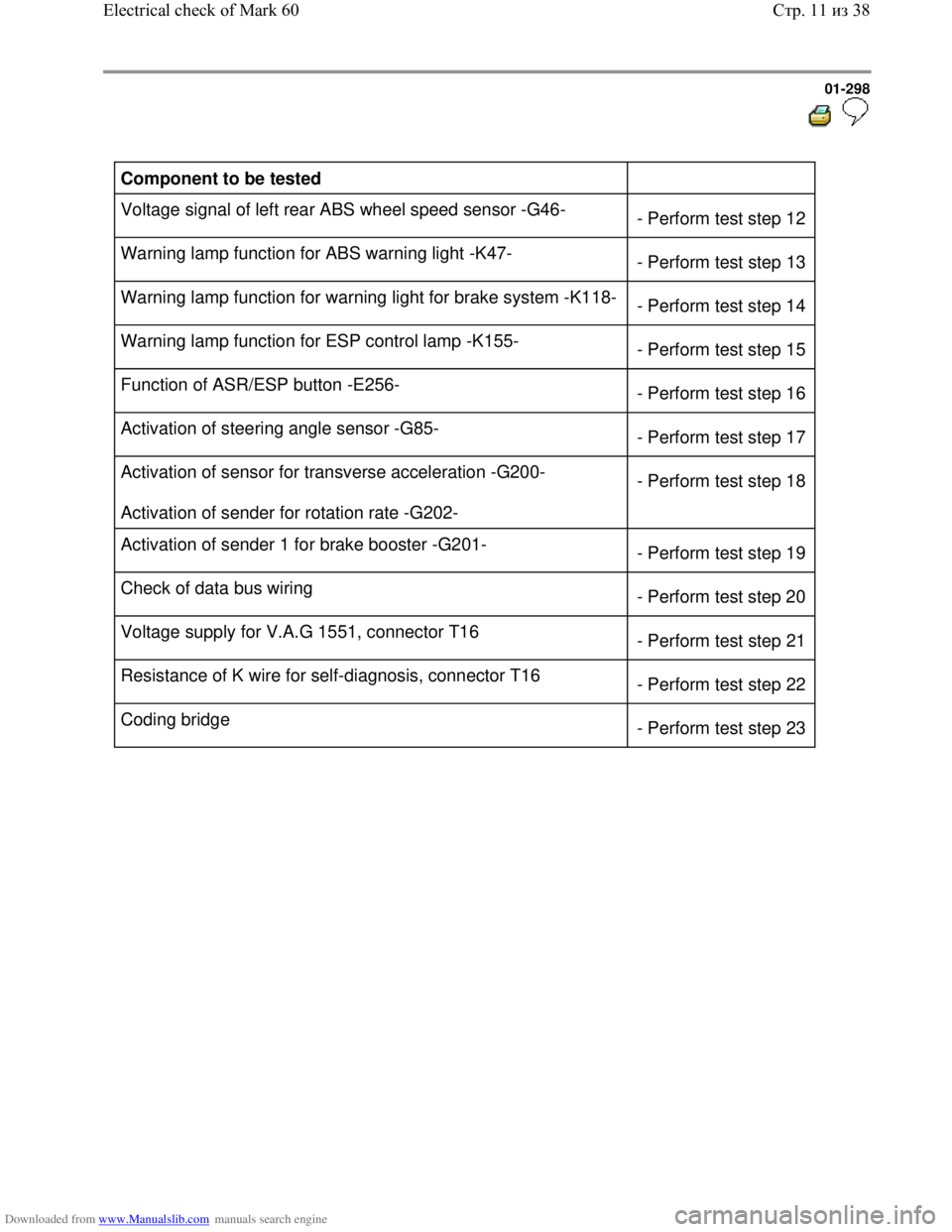
Test step overview
Component to be tested
Voltage supply for ABS hydraulic pump -V64- to ABS control module
(w/EDL) -J104- - Perform test
step 1
Voltage supply for valves in ABS hydraulic unit -N55- to ABS control
module (w/EDL) -J104- - Perform test
step 2
Voltage supply (ignition/starter switch) to ABS control module (w/EDL) -
J104- - Perform test
step 3
Function of brake light switch -F-
- Perform test
step 4
Resistance of right front ABS wheel speed sensor -G45-
- Perform test
step 5
Resistance of left front ABS wheel speed sensor -G47-
- Perform test
step 6
Resistance of right rear ABS wheel speed sensor -G44-
- Perform test
step 7
Resistance of left rear ABS wheel speed sensor -G46-
- Perform test
step 8
Voltage signal of right front ABS wheel speed sensor -G45-
- Perform test
step 9
Voltage signal of left front ABS wheel speed sensor -G47-
- Perform test
step 10
Voltage signal of right rear ABS wheel speed sensor -G44-
- Perform test
step 11
Стр. 10из 38 Electrical check of Mark 60
Page 306 of 339

Downloaded from www.Manualslib.com manuals search engine 01-298
Component to be tested
Voltage signal of left rear ABS wheel speed sensor -G46-
- Perform test step 12
Warning lamp function for ABS warning light -K47-
- Perform test step 13
Warning lamp function for warning light for brake system -K118-
- Perform test step 14
Warning lamp function for ESP control lamp -K155-
- Perform test step 15
Function of ASR/ESP button -E256-
- Perform test step 16
Activation of steering angle sensor -G85-
- Perform test step 17
Activation of sensor for transverse acceleration -G200-
Activation of sender for rotation rate -G202- - Perform test step 18
Activation of sender 1 for brake booster -G201-
- Perform test step 19
Check of data bus wiring
- Perform test step 20
Voltage supply for V.A.G 1551, connector T16
- Perform test step 21
Resistance of K wire for self-diagnosis, connector T16
- Perform test step 22
Coding bridge
- Perform test step 23
Стр. 11из 38 Electrical check of Mark 60
Page 309 of 339

Downloaded from www.Manualslib.com manuals search engine 01-301
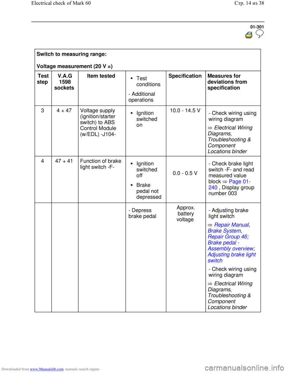
Switch to measuring range:
Voltage measurement (20 V =)
Test
step V.A.G
1598
sockets Item tested
Test
conditions
- Additional
operations Specification
Measures for
deviations from
specification
3 4 + 47 Voltage supply
(ignition/starter
switch) to ABS
Control Module
(w/EDL) -J104-
Ignition
switched
on 10.0 - 14.5 V
Electrical Wiring
Diagrams,
Troubleshooting &
Component
Locations binder - Check wiring using
wiring diagram
4 47 + 41 Function of brake
light switch -F- Ignition
switched
off
Brake
pedal not
depressed
0.0 - 0.5 V - Check brake light
switch -F- and read
measured value
block Page 01-
240 , Display group
number 003
- Depress
brake pedal Approx.
battery
voltage
Repair Manual,
Brake System,
Repair Group 46;
Brake pedal -
Assembly overview;
Adjusting brake light
switch
Electrical Wiring
Diagrams,
Troubleshooting &
Component
Locations binder - Adjusting brake
light switch
- Check wiring using
wiring diagram
Стр. 14из 38 Electrical check of Mark 60
Page 317 of 339
Downloaded from www.Manualslib.com manuals search engine 01-309
Functional check: Warning light for brake system -K118-
Test
step V.A.G
1598
sockets Item tested
Test
conditions
- Additional
operations Specification
Measures for
deviations from
specification
14 - Function of
warning light
for brake
system -
K118-
Parking
brake not
applied
Brake fluid
level OK
Ignition
switched
on Warning light for
brake system -
K118- does not
light up
- Apply
parking brake Warning light for
brake system -
K118- lights up
Electrical Wiring
Diagrams,
Troubleshooting &
Component Locations
binder
Repair Manual,
Body Interior,Repair
Group 70; instrument
panel - Check wiring using
wiring diagram
- Malfunction in
instrument cluster
Стр. 22из 38 Electrical check of Mark 60