Page 212 of 3115
MET Fuse Light Control Switch Flasher Relay
ABS, TRC, VSC ECU ABS, TRC, VSC ECU Drive Monitor H/L R-HI Fuse Body ECU
ABS, TRC, VSC ECU
ABS & BA & TRAC & VSC Actuator ECM
ABS, TRC, VSC ECU
Airbag ECU
Oil Pressure Sender Gauge Airbag ECU Body ECUWiring connector side No.107 6
19 18 175 3
12
20 15
16
17
18
19
7 4 1
C14 C13 C12
11
Gateway ECU
ECM Engine Ground
Main Fuel Sender Gauge
7
19
201
2
4
C15Key Unlock Warning Switch 9CTR DIFF Switch 14
Drive Monitor 16 10 ECM
Body (Door Courtesy Switch Signal) 10Flasher Relay 4
ABS, TRC, VSC ECU
ABS, TRC, VSC ECU
ABS, TRC, VSC ECU
GAUGE1 Fuse
ECU-B2 Fuse
ACC Fuse
DOME Fuse
Speed Sensor 11
12
13
14
15Main Fuel Sender Gauge
Light Control Rheostat 6 Main Fuel Sender GaugeBody Ground 9
Speed Control Unit 16PANEL Fuse 8
11 Driver Seat Belt Buckle Switch
- BODY ELECTRICALCOMBINATION METER
BE-61
2434 Author�: Date�:
2004 LAND CRUISER (RM1071U)
Page 416 of 3115

BO3XU-02
H21208
Center Bracket
No. 5 Heater to
Register Duct
Airbag Connector
H18914
H21406
: 5 Clips
- BODYINSTRUMENT PANEL
BO-91
2665 Author�: Date�:
2004 LAND CRUISER (RM1071U)
INSTALLATION
1. INSTALL REINFORCEMENT
2. INSTALL NO. 1 BRACE
3. INSTALL FLOOR BRACE
4. INSTALL GLOVE COMPARTMENT DOOR DAMPER
5. INSTALL NO. 4 HEATER TO REGISTER DUCT
6. INSTALL NO. 3 HEATER TO REGISTER DUCT
7. INSTALL ECM (See page SF-60)
8. INSTALL INSTRUMENT PANEL
HINT:
�Install the airbag connector between the No. 5 heater to
register duct and the center bracket temporarily, then
install the instrument panel.
�Remove the airbag connector before installing the lower
No. 2 panel.
(a) Install the 6 bolts, the 2 nuts and the instrument panel,
then connect the connectors.
(b) Install the 2 bolts to the front passenger airbag assembly.
Torque: 20 N´m (204 kgf´cm, 15 ft´lbf)
(c) Connect the junction connectors.
HINT:
The connectors can be connected by tightening the bolts.
9. INSTALL FRONT CONSOLE BOX AND FRONT CON-
SOLE BOX BRACKET
Install the front console box and the front console box bracket
with the 2 bolts.
10. INSTALL CENTER LOWER CLUSTER FINISH PANEL
Connect the connector, then install the center lower cluster fin-
ish panel.
Page 426 of 3115
H18914
H18915
BO-88
- BODYINSTRUMENT PANEL
2662 Author�: Date�:
2004 LAND CRUISER (RM1071U)
28. REMOVE FRONT CONSOLE BOX AND FRONT CON-
SOLE BOX BRACKET
Remove the 2 bolts, the front console box and the front console
box bracket.
29. REMOVE INSTRUMENT PANEL
(a) Disconnect the junction connectors.
HINT:
The connectors can be disconnected by loosening the bolts.
(b) Disconnect the connector, then remove the 8 bolts, the 2
nuts and the instrument panel.
30. REMOVE ECM (See page SF-60)
31. REMOVE NO. 3 HEATER TO REGISTER DUCT
32. REMOVE NO. 4 HEATER TO REGISTER DUCT
33. REMOVE GLOVE COMPARTMENT DOOR DAMPER
34. REMOVE FLOOR BRACE
35. REMOVE NO. 1 BRACE
36. REMOVE REINFORCEMENT
Page 789 of 3115
F17613
Normal Signal Waveform
1 V /
Division
2 m/s / DivisionGND
- DIAGNOSTICSABS & VEHICLE STABILITY CONTROL (VSC) &
BRAKE ASSIST (BA) SYSTEMDI-537
730 Author�: Date�:
2004 LAND CRUISER (RM1071U)
INSPECTION PROCEDURE
1 Check skid control ECU communication.
(REFERENCE) INSPECTION USING OSCILLOSCOPE
PREPARATION:
(a) Remove the skid control ECU.
(b) Connect the oscilloscope to each of terminal ENG+ or
TRC+ and GND of the skid control ECU.
CHECK:
Start the engine, and check the signal waveform.
NG Check and replace skid control ECU.
OK
2 Check for open and short circuit in harness and connector between each of ter-
minals ENG+, ENG-, TRC+, TRC- of skid control ECU and ECM (See page
IN-36).
NG Repair or replace harness or connector.
OK
Check and replace ECM.
Page 791 of 3115
- DIAGNOSTICSABS & VEHICLE STABILITY CONTROL (VSC) &
BRAKE ASSIST (BA) SYSTEMDI-539
732 Author�: Date�:
2004 LAND CRUISER (RM1071U)
INSPECTION PROCEDURE
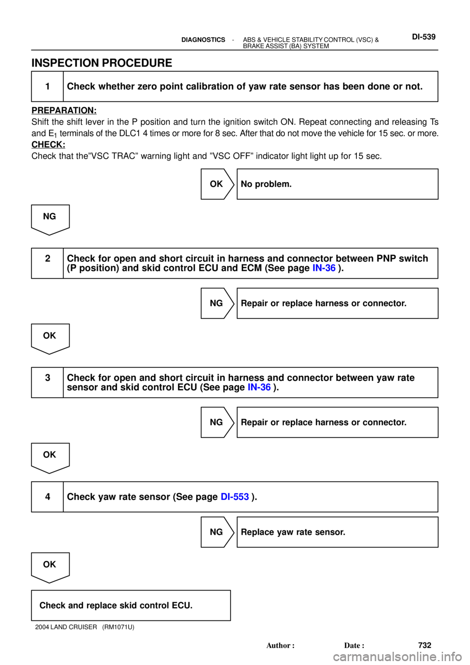
1 Check whether zero point calibration of yaw rate sensor has been done or not.
PREPARATION:
Shift the shift lever in the P position and turn the ignition switch ON. Repeat connecting and releasing Ts
and E
1 terminals of the DLC1 4 times or more for 8 sec. After that do not move the vehicle for 15 sec. or more.
CHECK:
Check that theºVSC TRACº warning light and ºVSC OFFº indicator light light up for 15 sec.
OK No problem.
NG
2 Check for open and short circuit in harness and connector between PNP switch
(P position) and skid control ECU and ECM (See page IN-36).
NG Repair or replace harness or connector.
OK
3 Check for open and short circuit in harness and connector between yaw rate
sensor and skid control ECU (See page IN-36).
NG Repair or replace harness or connector.
OK
4 Check yaw rate sensor (See page DI-553).
NG Replace yaw rate sensor.
OK
Check and replace skid control ECU.
Page 793 of 3115

F17754
ABS & BA & TRAC
& VSC ECU
ECM
J/B No.5
NEO A427
W
5D 12
5
5C E9W
NEO17
- DIAGNOSTICSABS & VEHICLE STABILITY CONTROL (VSC) &
BRAKE ASSIST (BA) SYSTEMDI-541
734 Author�: Date�:
2004 LAND CRUISER (RM1071U)
DTC C1224 / 44 NE Signal Circuit
CIRCUIT DESCRIPTION
The skid control ECU receives engine revolution speed signals (NE signals) from the ECM.
DTC No.DTC Detecting ConditionTrouble Area
C1224 / 44
When either of the following 1. or 2. is detected:
1. At vehicle speed of 19 mph (30 km/h) or more, and
when data received from the ECM is in normal condition,
and open or short circuit for engine revolution signal
circuit continues for 10 sec. or more.
2. While TRAC is operating, the conditions that open or
short circuit in engine revolution signal circuit is de-
tected, main throttle opening degree is 0 and IDL switch
is OFF continue for 0.24 sec. or more.
�NEO circuit
�ECM
�Skid control ECU
WIRING DIAGRAM
INSPECTION PROCEDURE
1 Check for open and short circuit in harness and connector between terminal
NEO of skid control ECU and terminal NEO of ECM (See page
IN-36).
NG Repair or replace harness and connector.
OK
DIC9G-01
Page 794 of 3115
F02807
ON
NEO
(+)
(-)
F03007
(Reference)
10 to 14 V
Below 1 V
DI-542- DIAGNOSTICSABS & VEHICLE STABILITY CONTROL (VSC) &
BRAKE ASSIST (BA) SYSTEM
735 Author�: Date�:
2004 LAND CRUISER (RM1071U)
2 Check voltage between terminal NEO of skid control ECU and body ground.
PREPARATION:
Remove the skid control ECU with connectors still connected.
CHECK:
(a) Turn the ignition switch ON.
(b) Measure voltage between terminal NEO of the skid con-
trol ECU and body ground for the engine conditions be-
low.
OK:
Engine conditionVoltage
OFF (IG ON)10 to 14 V or below 1 V
ON (Idling)10 to 14 V e below 1 V (Pulse)
NG Check and replace skid control ECU or ECM.
OK
If the same codes are still output after the DTC is deleted, check the contact condition of each
connection.
Page 859 of 3115
- DIAGNOSTICSABS & VEHICLE STABILITY CONTROL (VSC) &
BRAKE ASSIST (BA) SYSTEMDI-607
800 Author�: Date�:
2004 LAND CRUISER (RM1071U)
4 Check for open or short circuit in harness and connector between skid control
ECU and ECM (See page IN-36).
NG Repair or replace harness or connector.
OK
Check and replace skid control ECU.