Page 332 of 1463
1B3-30 OM600 ENGINE MECHANICAL
Tools Required
2. Install the sliding hammer into the prechamber.
Sliding Hammer 667 589 03 63 00
Removal & Installation Procedure
1. Using the serration wrench (4), remove the threaded ring
(1).
Serration Wrench 603 589 00 09 00
3. Remove the perchamber (2).
Notice
After removing the prechamber, cover over the bores with
clean rag. 603 589 00 09 00 Serration Wrench
667 589 03 63 00 Sliding Hammer
4. Inspect the prechamber.
Notice
If the prechamber seats in the cylinder head are leaking or
if the prechambers are replaced, the sealing surfaces in
the cylinder head must be remachined.
Page 908 of 1463
3D-10 REAR DRIVE AXLE
6. Separate the lower shock absorber from the axle housing.
Installation Notice
7. Remove the upper arm mounting nuts and remove the
upper arm form the axle housing.
Installation Notice
Tightening Torque 50 - 65 Nm
8. Remove the stabilizer bar.
Installation Notice
Tightening Torque 150 - 180 Nm
9. Remove the lateral rod mounting nuts and remove the
lateral rod from the axle housing.
Installation Notice
Tightening Torque 30 - 45 Nm
10. Lowering the axle housing slowly, remove the coil springs
and spring seats.
11. Installation should follow the removal precedure in the
reverse order.
Tightening Torque 150 - 180 Nm
Page 1254 of 1463

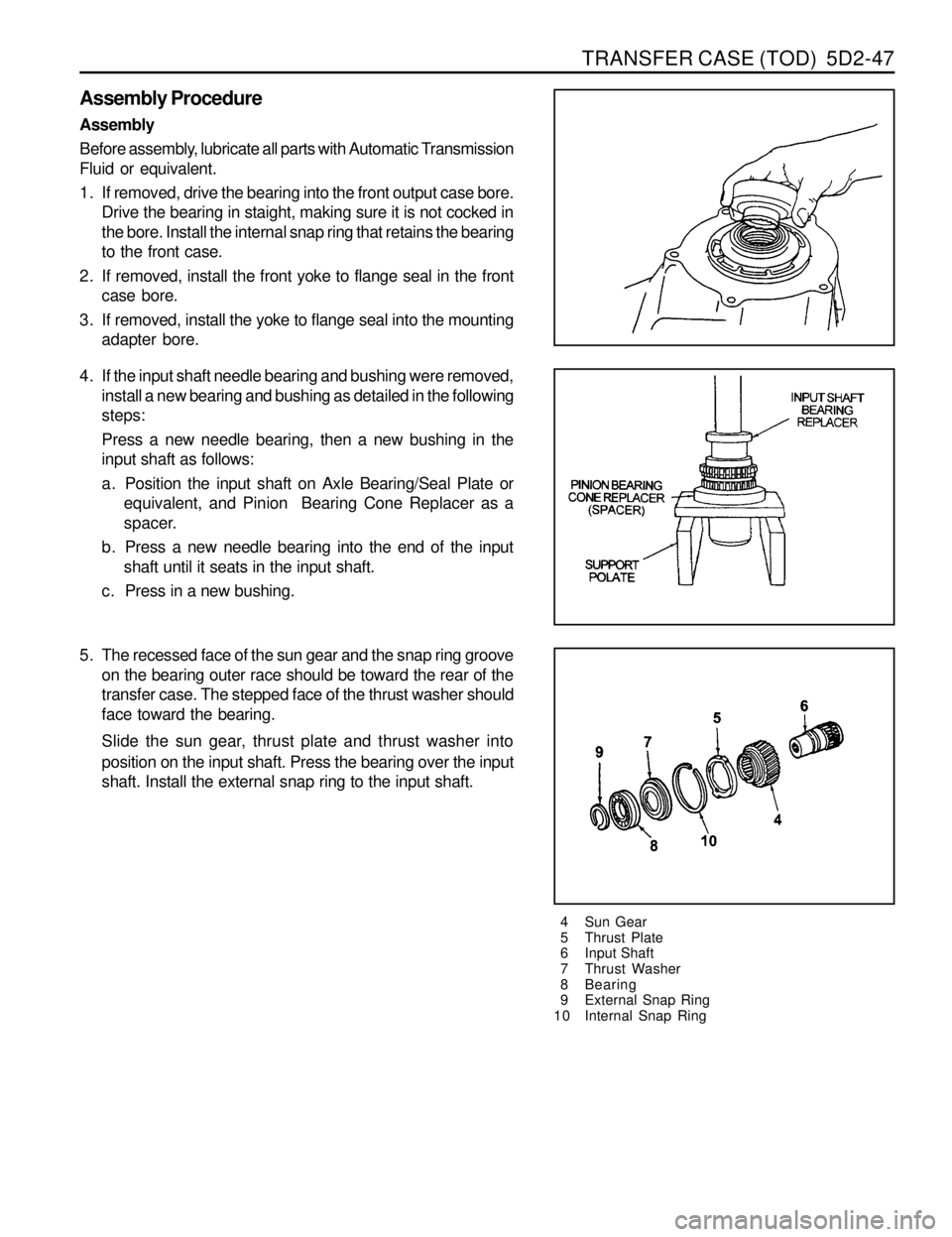
TRANSFER CASE (TOD) 5D2-47
Assembly Procedure
Assembly
Before assembly, lubricate all parts with Automatic Transmission
Fluid or equivalent.
1. If removed, drive the bearing into the front output case bore.
Drive the bearing in staight, making sure it is not cocked in
the bore. Install the internal snap ring that retains the bearing
to the front case.
2. If removed, install the front yoke to flange seal in the front
case bore.
3. If removed, install the yoke to flange seal into the mounting
adapter bore.
4 Sun Gear
5 Thrust Plate
6 Input Shaft
7 Thrust Washer
8 Bearing
9 External Snap Ring
10 Internal Snap Ring
4. If the input shaft needle bearing and bushing were removed,
install a new bearing and bushing as detailed in the following
steps:
Press a new needle bearing, then a new bushing in the
input shaft as follows:
a. Position the input shaft on Axle Bearing/Seal Plate or
equivalent, and Pinion Bearing Cone Replacer as a
spacer.
b. Press a new needle bearing into the end of the input
shaft until it seats in the input shaft.
c. Press in a new bushing.
5. The recessed face of the sun gear and the snap ring groove
on the bearing outer race should be toward the rear of the
transfer case. The stepped face of the thrust washer should
face toward the bearing.
Slide the sun gear, thrust plate and thrust washer into
position on the input shaft. Press the bearing over the input
shaft. Install the external snap ring to the input shaft.