Page 72 of 1463

1A3-14 GENERAL ENGINE INFORMATION
Leakage Test
1. Run the engine to be the coolant temperature 80°C.
2. Remove the fuel injection nozzle.
3. Open the coolant subtank cap.
4. Check the coolant level and replenish if necessary.
5. Open the oil filler cap.
6. Remove the air cleaner cover and element.
7. Position the piston at TDC.
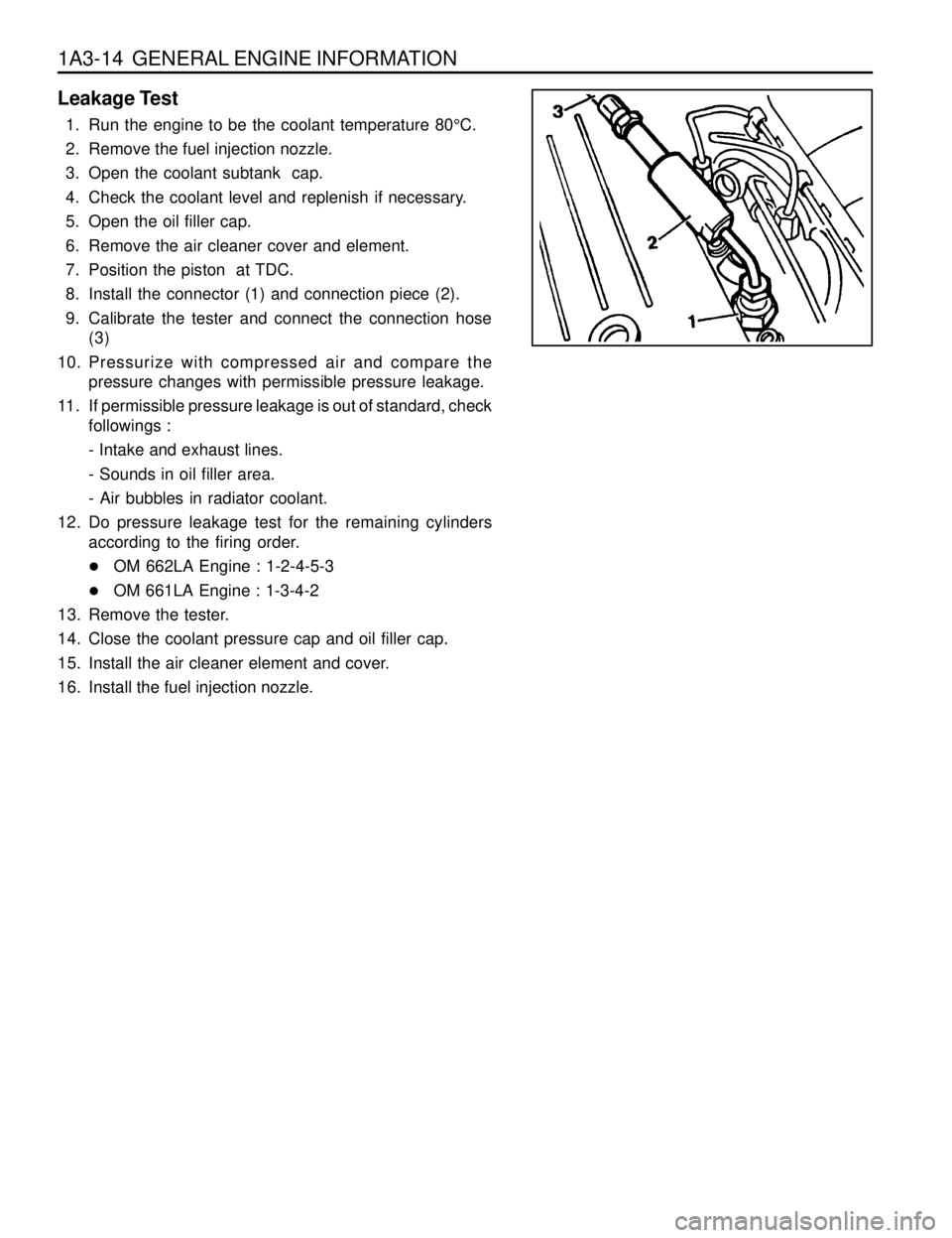
8. Install the connector (1) and connection piece (2).
9. Calibrate the tester and connect the connection hose
(3)
10. Pressurize with compressed air and compare the
pressure changes with permissible pressure leakage.
11. If permissible pressure leakage is out of standard, check
followings :
- Intake and exhaust lines.
- Sounds in oil filler area.
- Air bubbles in radiator coolant.
12. Do pressure leakage test for the remaining cylinders
according to the firing order.
lOM 662LA Engine : 1-2-4-5-3
lOM 661LA Engine : 1-3-4-2
13. Remove the tester.
14. Close the coolant pressure cap and oil filler cap.
15. Install the air cleaner element and cover.
16. Install the fuel injection nozzle.
Page 166 of 1463

M162 ENGINE MECHANICAL 1B1-93
OIL PAN
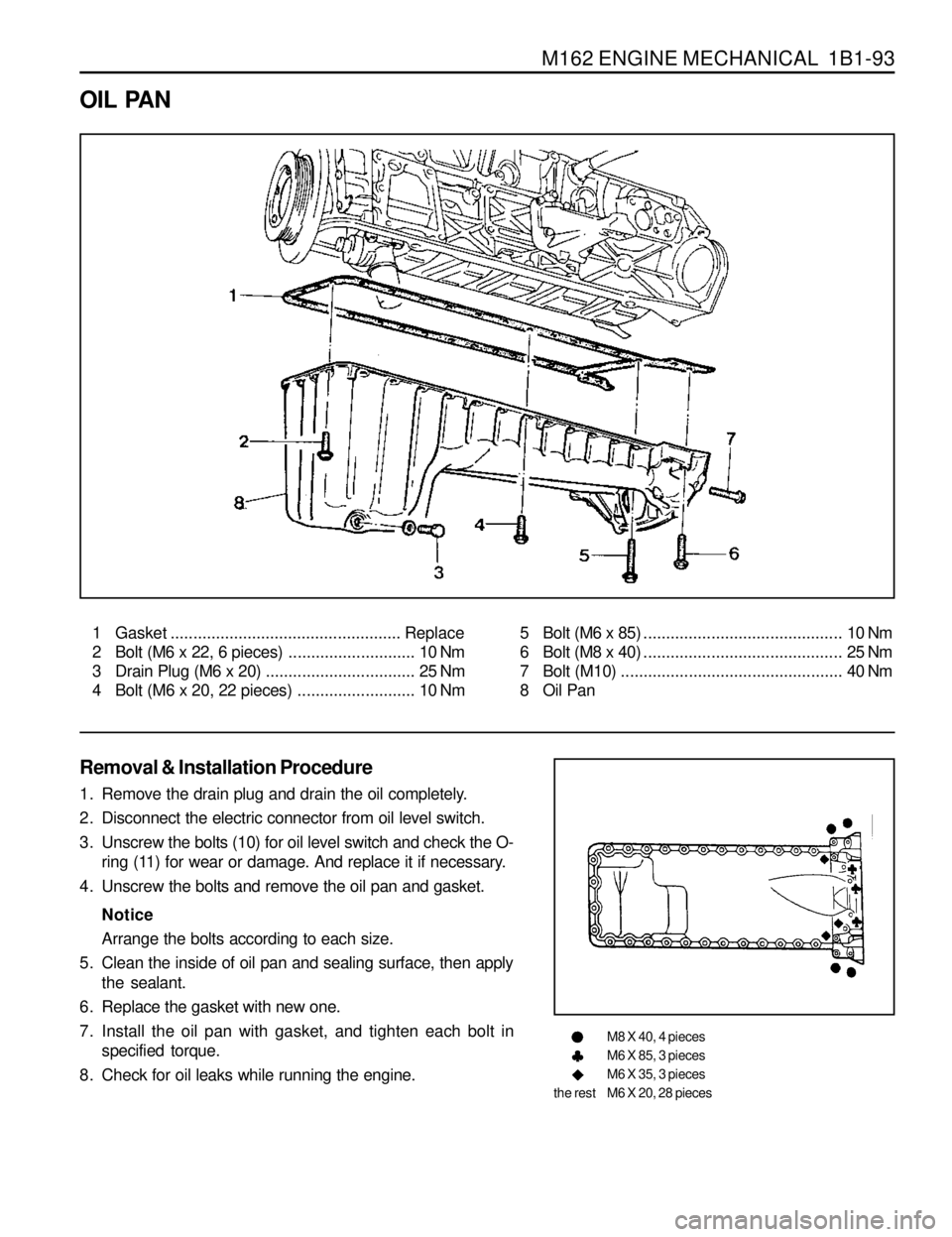
1 Gasket ................................................... Replace
2 Bolt (M6 x 22, 6 pieces)............................ 10 Nm
3 Drain Plug (M6 x 20)................................. 25 Nm
4 Bolt (M6 x 20, 22 pieces).......................... 10 Nm5 Bolt (M6 x 85)............................................ 10 Nm
6 Bolt (M8 x 40)............................................ 25 Nm
7 Bolt (M10)................................................. 40 Nm
8 Oil Pan
Removal & Installation Procedure
1. Remove the drain plug and drain the oil completely.
2. Disconnect the electric connector from oil level switch.
3. Unscrew the bolts (10) for oil level switch and check the O-
ring (11) for wear or damage. And replace it if necessary.
4. Unscrew the bolts and remove the oil pan and gasket.
Notice
Arrange the bolts according to each size.
5. Clean the inside of oil pan and sealing surface, then apply
the sealant.
6. Replace the gasket with new one.
7. Install the oil pan with gasket, and tighten each bolt in
specified torque.
8. Check for oil leaks while running the engine.
M8 X 40, 4 pieces
M6 X 85, 3 pieces
M6 X 35, 3 pieces
M6 X 20, 28 pieces the rest
Page 169 of 1463
1B1-96 M162 ENGINE MECHANICAL
3 Oil Filler Cap
4 Dipstick Gauge
9. Fill up engine oil through the engine oil filler opening (3).
10. Check for oil leaks at normal engine temperature after
starting the engine.
11. Stop the engine and wait 5 minutes.
Check the oil level and fill up as specified if necessary.
Page 171 of 1463
1B1-98 M162 ENGINE MECHANICAL
Tightening Torque 23 Nm
Notice
Replace the oil filter gasket.
4. Installation should follow the removal procedure in the
reverse order.
5. Check engine oil level.
6. Run the engine at idle and check the engine for leaks. 3. Remove the oil filter bolt and then remove the oil filter.
Installation Notice
Removal & Installation Procedure
1. Drain the coolant from the crank case.
2. Remove the each coolant line and hose.
Page 176 of 1463
M162 ENGINE MECHANICAL 1B1-103
OIL DIPSTICK GUIDE TUBE
1 Oil Dipstick Level Gauge
2 Oil Dipstick Guide Tube
Removal & Installation Procedure
1. Pull out the oil dipstick level gauge (1).
2. Remove the bolt (4) in the upper intake manifold and remove
the oil dipstick guide tube.
Installation Notice
3. Install new O-ring to the dipstick guide tube.
4. Installation should follow the removal procedure in the
reverse order.
5. Check for leaks by starting the engine.3 O-ring
4 Bolt (M6 x 12, 1 piece)........................... 9-11 Nm
Tightening Torque 9 - 11 Nm
Page 289 of 1463

1B2-100 M161 ENGINE MECHANICAL
9. Fill up engine oil through the engine oil filler opening.
10. Check for oil leaks at normal engine temperature after
starting the engine.
11. Stop the engine and wait 5 minutes.
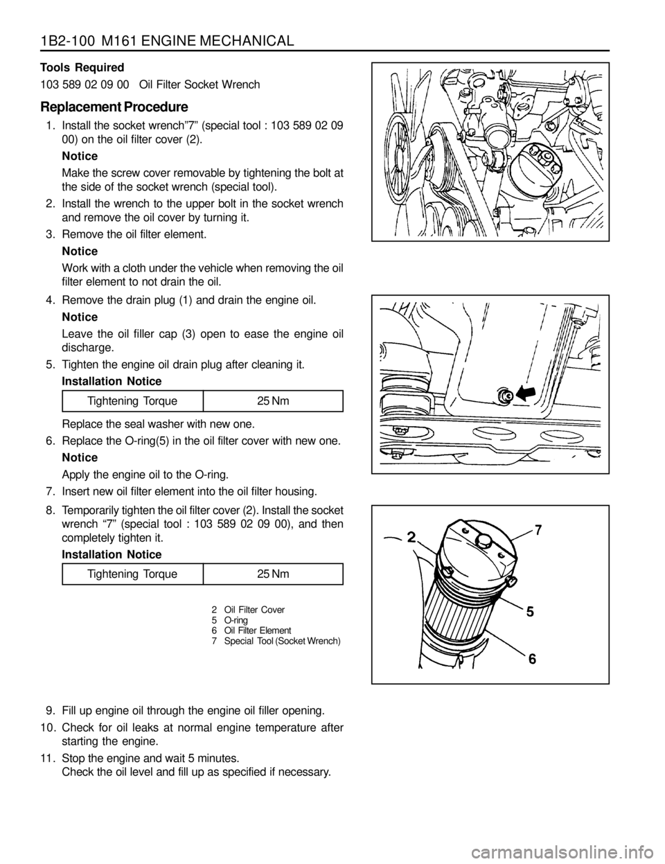
Check the oil level and fill up as specified if necessary. 4. Remove the drain plug (1) and drain the engine oil.
Notice
Leave the oil filler cap (3) open to ease the engine oil
discharge.
5. Tighten the engine oil drain plug after cleaning it.
Installation Notice Tools Required
103 589 02 09 00 Oil Filter Socket Wrench
Replacement Procedure
1. Install the socket wrench”7” (special tool : 103 589 02 09
00) on the oil filter cover (2).
Notice
Make the screw cover removable by tightening the bolt at
the side of the socket wrench (special tool).
2. Install the wrench to the upper bolt in the socket wrench
and remove the oil cover by turning it.
3. Remove the oil filter element.
Notice
Work with a cloth under the vehicle when removing the oil
filter element to not drain the oil.
Replace the seal washer with new one.
6. Replace the O-ring(5) in the oil filter cover with new one.
Notice
Apply the engine oil to the O-ring.
7. Insert new oil filter element into the oil filter housing.
Tightening Torque 25 Nm
8. Temporarily tighten the oil filter cover (2). Install the socket
wrench “7” (special tool : 103 589 02 09 00), and then
completely tighten it.
Installation Notice
2 Oil Filter Cover
5 O-ring
6 Oil Filter Element
7 Special Tool (Socket Wrench)
Tightening Torque 25 Nm
Page 294 of 1463
M161 ENGINE MECHANICAL 1B2-105
OIL DIPSTICK GUIDE TUBE
1 Oil Dipstick Level Gauge
2 Oil Dipstick Guide Tube
3 O-ring
Removal & Installation Procedure
1. Pull out the oil dipstick level gauge (1).
2. Unscrew the bolt (4) and remove the oil dipstick guide
tube (2).
Installation Notice4 Bolt (M6 X 16, 1 piece)........................... 9-11 Nm
5 Clamp
Tightening Torque 9 - 11 Nm
It is very hard to remove the oil dipstick guide tube without
special tool. If it is not necessary, do not remove the guide
tube.
3. Installation should follow the removal procedure in the
reverse order.
4. Check for leaks by starting the engine.
Page 394 of 1463

1B3-92 OM600 ENGINE MECHANICAL
28. Remove the connecting rod bearing cap.
29. Install the piston.
30. Rotate the crankshaft by hand and check whether it rotates
smoothly.
31. If the bearings are damaged,
- replace the oil presser relief valve.
- clean the oil pump and oil filter housing carefully and
replace the hose if necessary.
Notice
After assembling the engine, check the camshaft timing,
adjust the start of fuel injection and check the TDC sensor
bracket setting.
32. Fill oil and run the engine and then check the oil pressure
and oil level.
Notice
Install the original oil filter element and then change the
engine oil and oil filter element after 1,000 - 1,500km. 27. Measure the radial clearance (L) of the connecting rod
bearing.
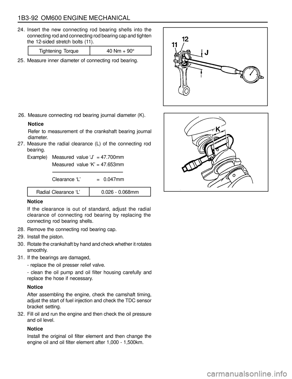
Example)Measured value ‘J’ = 47.700mm
Measured value ‘K’ = 47.653mm
Clearance ‘L’ = 0.047mm
Radial Clearance ‘L’ 0.026 - 0.068mm
Notice
If the clearance is out of standard, adjust the radial
clearance of connecting rod bearing by replacing the
connecting rod bearing shells. 26. Measure connecting rod bearing journal diameter (K).
Notice
Refer to measurement of the crankshaft bearing journal
diameter.
24. Insert the new connecting rod bearing shells into the
connecting rod and connecting rod bearing cap and tighten
the 12-sided stretch bolts (11).
25. Measure inner diameter of connecting rod bearing.
Tightening Torque 40 Nm + 90°