Page 420 of 1463
1B3-118 OM600 ENGINE MECHANICAL
2. Thoroughly clean the basic bore by using a cylinder brush.
Cylinder Brush 000 589 10 68 00
3. Check the basic bore in cylinder head for scoring marks
and ream to next repair size if necessary.
2. Insert the GO/NO GO gauge into the valve guide bore. If
the NO GO side is inserted fully, replace the valve guide
(Intake 8mm, Exhaust 9mm).
GO/NO GO Gauge 601 589 02 23 00
Replacement Procedure
1. Drive out the valve guide (2) by using a drift (5).
Notice
The valve guide must be driven out upward of the cylinder
head.
Drift (for Intake) 103 589 03 15 00
Drift (for Exhaust) 103 589 02 15 00
Checking
1. Thoroughly clean the valve guide bore using a cylinder
brush.
Cylinder Brush 000 589 10 68 00
Page 422 of 1463
1B3-120 OM600 ENGINE MECHANICAL
8. Check the valve guide bore with GO / NO GO gauge (9).
The GO side (marked ‘0’) should just still drop. If the GO
side cannot be inserted, the bore of valve guide should be
reamed.
Notice
Perform the check only on cooled down cylinder head.
GO / NO GO Gauge (for Intake) 102 589 00 23 00
GO / NO GO Gauge (for Exhaust) 117 589 03 23 00
6. Cool down the new valve guide (2) with liquid nitrogen.
Notice
Do not touch the cooled valve guide by hand.
Super Cooling box 346 589 00 63 00
7. Drive in new valve guide with drift (8) until the wire ring makes
contact.
Notice
The valve guide must be driven in from the cylinder head
cover.
Drift (for Intake) 601 589 05 15 00
Drift (for Exhaust) 601 589 06 15 00
5. Heat the cylinder head (1) in a wear tank to approx. 80°C.
Page 424 of 1463
1B3-122 OM600 ENGINE MECHANICAL
VALVE SEAT RINGS
Preceding Work : Removal of valve
Checking of valve guide, replace if necessary
Removal of prechamber
1 Cylinder Head
2 Valve Seat Ring
3 Valve Guide
A Height (Cylinder Head Upper / Lower Surface)
B Height (cylinder Head Cover Surface - Seat of
Valve Seat Ring)D Valve Seat Ring Outer Diameter
D1 Valve Seat Ring Inner Diameter
D2 Basic Bore Diameter
H Height of Valve Seat Ring
Service Data
Item
D2
D
D1
H
Overlap U=D-D2
B
AIntake
40.000 - 40.016mm
40.084 - 40.100mm
33.400 - 33.600mm
6.955 - 7.045mm
0.068 - 0.100mm
133.4mm
142.5mmExhaust
37.000 - 37.016mm
37.084 - 37.100mm
30.400 - 30.600mm
6.955 - 7.045mm
0.068 - 0.100mm
133.4mm
142.5mm
Page 429 of 1463
OM600 ENGINE MECHANICAL 1B3-127
CHECK AND MACHINING OF VALVES
Preceding Works : Removal of cylinder head
Removal of the vale spring
Removal of the valve
I Valve Length
W Camshaft Cam Basic Diameter
X Distance (Camshaft Basic Bore - Valve Stem)Y Half Camshaft Basic Bore Diameter
Z Distance (Cylinder Head Cover Parting Surface -
Valve Stem)
Page 431 of 1463
OM600 ENGINE MECHANICAL 1B3-129
Tools Required
001 589 32 21 00 Dial Gauge
Checking and Machining
1. Clean the valves and do visual check.
Valves with wobbled valve disc, with worn or scored valve
stem should be replaced.
2. Measure valve disc height ‘h’.
Service data
Intake
Exhaust1.7 ± 0.15 mm
1.7 ± 0.15 mm
3. Machine the valve.
Notice
Pay attention to setting angle ‘a’.
Commercial Tool
Valve corn grinding machine
4. Measure radial runout between valve stem and valve seat.
Limit Max. 0.03mm
Dial Gauge 001 589 32 21 00
Page 440 of 1463

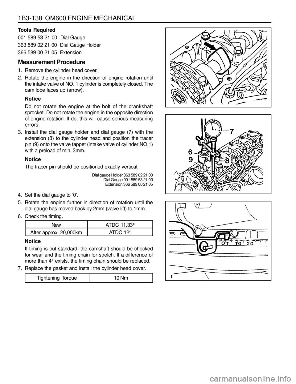
1B3-138 OM600 ENGINE MECHANICAL
6. Check the timing.
New
After approx. 20,000kmATDC 11.33°
ATDC 12°
Notice
If timing is out standard, the camshaft should be checked
for wear and the timing chain for stretch. If a difference of
more than 4° exists, the timing chain should be replaced.
7. Replace the gasket and install the cylinder head cover.
Tightening Torque 10 Nm
Measurement Procedure
1. Remove the cylinder head cover.
2. Rotate the engine in the direction of engine rotation until
the intake valve of NO. 1 cylinder is completely closed. The
cam lobe faces up (arrow).
Notice
Do not rotate the engine at the bolt of the crankshaft
sprocket. Do not rotate the engine in the opposite direction
of engine rotation. If do, this will cause serious measuring
errors.
3. Install the dial gauge holder and dial gauge (7) with the
extension (8) to the cylinder head and position the tracer
pin (9) onto the valve tappet (intake valve of cylinder NO.1)
with a preload of min. 3mm.
Notice
The tracer pin should be positioned exactly vertical.
Dial gauge Holder 363 589 02 21 00
Dial Gauge 001 589 53 21 00
Extension 366 589 00 21 05
4. Set the dial gauge to ‘0’.
5. Rotate the engine further in direction of rotation until the
dial gauge has moved back by 2mm (valve lift) to 1mm.
Tools Required
001 589 53 21 00 Dial Gauge
363 589 02 21 00 Dial Gauge Holder
366 589 00 21 05 Extension
Page 441 of 1463
OM600 ENGINE MECHANICAL 1B3-139
CAMSHAFT
Preceding Work : Removal of cylinder head cover
1 Bolt............................................................25Nm
2 Washer
3 Camshaft Bearing Cap
4 Camshaft
5 Dowel Pin
6 Locking Washer
7 Timing Chain8 Cylinder Head
9 Oil Pan
10 Camshaft Sprocket
11 Washer
12 12-Sided Bolt (M11).............Check, 25Nm + 90°
13 Gasket ................................................... Replace
14 Chain Tensioner........................................80Nm
Page 444 of 1463
1B3-142 OM600 ENGINE MECHANICAL
4. Install the camshaft bearing caps according to markings(1,
2, 3 etc.).
7. Remove the camshaft bearing cap.
8. Pull off the camshaft.
Notice
Be careful not to miss front locking washer.
9. Pull out the locking washer.
Notice
Check the condition of locking washer and replace if
necessary.
Installation Procedure
1. Insert the locking washer.
2. Check the valve tappet and ensure that tappet moves
smoothly.
3. Coat the camshaft with oil and install the camshaft onto the
cylinder head so that the TDC marking (arrow) is positioned
upward vertically.