1998 OPEL FRONTERA 1000
[x] Cancel search: 1000Page 452 of 6000

4A1–15 DIFFERENTIAL (FRONT)
8. Select the shim using the chart;
Pinion marking+10+8+6+4+20–2–4–6–8–10
Dial indicator
reading
(Inches)mm
(Inches)mm
(Inches)mm
(Inches)mm
(Inches)mm
(Inches)mm
(Inches)mm
(Inches)mm
(Inches)mm
(Inches)mm
(Inches)mm
(Inches)
0.0812.18
(0.0858)
0.0822.18
(0.0858)2.20
(0.0866)
0.0832.18
(0.0858)2.20
(0.0866)2.23
(0.0882)
0.0842.18
(0.0858)2.20
(0.0866)2.24
(0.0882)2.26
(0.0890)
0.0852.18
(0.0858)2.20
(0.0866)2.24
(0.0882)2.26
(0.0890)2.28
(0.0898)
0.0862.18
(0.0858)2.20
(0.0866)2.24
(0.0882)2.26
(0.0890)2.28
(0.0898)2.32
(0.0914)
0.0872.18
(0.0858)2.20
(0.0866)2.24
(0.0882)2.26
(0.0890)2.28
(0.0898)2.32
(0.0914)2.34
(0.0921)
0.0882.18
(0.0858)2.20
(0.0866)2.24
(0.0882)2.26
(0.0890)2.28
(0.0898)2.32
(0.0914)2.34
(0.0921)2.36
(0.0929)
0.0892.18
(0.0858)2.20
(0.0866)2.24
(0.0882)2.26
(0.0890)2.28
(0.0898)2.32
(0.0914)2.34
(0.0921)2.36
(0.0929)2.38
(0.0937)
0.0902.18
(0.0858)2.20
(0.0866)2.24
(0.0882)2.26
(0.0890)2.28
(0.0898)2.32
(0.0914)2.34
(0.0921)2.36
(0.0929)2.38
(0.0937)2.42
(0.0953)
0.0912.18
(0.0858)2.20
(0.0866)2.24
(0.0882)2.26
(0.0890)2.28
(0.0898)2.32
(0.0914)2.34
(0.0921)2.36
(0.0929)2.38
(0.0937)2.42
(0.0953)2.44
(0.0961)
0.0922.20
(0.0866)2.24
(0.0882)2.26
(0.0890)2.28
(0.0898)2.32
(0.0914)2.34
(0.0921)2.36
(0.0929)2.38
(0.0937)2.42
(0.0953)2.44
(0.0961)2.46
(0.0969)
0.0932.24
(0.0882)2.26
(0.0890)2.28
(0.0898)2.32
(0.0914)2.34
(0.0921)2.36
(0.0929)2.38
(0.0937)2.42
(0.0953)2.44
(0.0961)2.46
(0.0969)2.48
(0.0977)
0.0942.26
(0.0890)2.28
(0.0898)2.32
(0.0914)2.34
(0.0921)2.36
(0.0929)2.38
(0.0937)2.42
(0.0953)2.44
(0.0961)2.46
(0.0969)2.48
(0.0977)2.52
(0.0992)
0.0952.28
(0.0898)2.32
(0.0914)2.34
(0.0921)2.36
(0.0929)2.38
(0.0937)2.42
(0.0953)2.44
(0.0961)2.46
(0.0969)2.48
(0.0977)2.52
(0.0992)2.54
(0.1000)
0.0962.32
(0.0914)2.34
(0.0921)2.36
(0.0929)2.38
(0.0937)2.42
(0.0953)2.44
(0.0961)2.46
(0.0969)2.48
(0.0977)2.52
(0.0992)2.54
(0.1000)2.56
(0.1008)
0.0972.34
(0.0921)2.36
(0.0929)2.38
(0.0937)2.42
(0.0953)2.44
(0.0961)2.46
(0.0969)2.48
(0.0977)2.52
(0.0992)2.54
(0.1000)2.56
(0.1008)
0.0982.36
(0.0929)2.38
(0.0937)2.42
(0.0953)2.44
(0.0961)2.46
(0.0969)2.48
(0.0977)2.52
(0.0992)2.54
(0.1000)2.56
(0.1008)
0.0992.38
(0.0937)2.42
(0.0953)2.44
(0.0961)2.46
(0.0969)2.48
(0.0977)2.52
(0.0992)2.54
(0.1000)2.56
(0.1008)
02.42
(0.0953)2.44
(0.0961)2.46
(0.0969)2.48
(0.0977)2.52
(0.0992)2.54
(0.1000)2.56
(0.1008)
0.0012.44
(0.0961)2.46
(0.0969)2.48
(0.0977)2.52
(0.0992)2.54
(0.1000)2.56
(0.1008)
0.0022.46
(0.0969)2.48
(0.0977)2.52
(0.0992)2.54
(0.1000)2.56
(0.1008)
0.0032.48
(0.0977)2.52
(0.0992)2.54
(0.1000)2.56
(0.1008)
0.0042.52
(0.0992)2.54
(0.1000)2.56
(0.1008)
0.0052.54
(0.1000)2.56
(0.1008)
0.0062.56
(0.1008)
NOTE: When ordering shims, find the part number in the
parts catalog by using the thickness of shims listed in the
above table.4. Place the shim on the drive pinion, with the chamfered
side turned towards the pinion head then install the
inner bearing onto the pinion using an installer
9–8522–1165–0 and a press.
Page 961 of 6000

6A–5
ENGINE MECHANICAL
4. Engine Lacks Compression
Condition
Possible causeCorrection
Engine lacks compressionSpark plug loosely fitted or spark
plug gasket defectiveTighten to specified torque or replace
gasket
Valve timing incorrectAdjust
Cylinder head gasket defectiveReplace gasket
Valve incorrectly seatedLap valve
Valve stem seizedReplace valve and valve guide
Valve spring weakened or brokenReplace
Cylinder or piston rings wornOverhaul engine
Piston ring seizedOverhaul engine.
Engine Compression Test Procedure
1. Start and run the engine until the engine reaches
normal operating temperature.
2. Turn the engine off.
3. Remove all the spark plugs.
4. Remove ignition coil fuse (15A) and disable the
ignition system.
5. Remove the fuel pump relay from the relay and fuse
box.
6. Engage the starter and check that the cranking speed
is approximately 300 rpm.7. Install cylinder compression gauge into spark plug
hole.
8. With the throttle valve opened fully, keep the starter
engaged until the compression gage needle reaches
the maximum level. Note the reading.
9. Repeat the test with each cylinder.
If the compression pressure obtained falls below the
limit, engine overhaul is necessary.
Limit; 1000 kPa (145 psi)
Page 1185 of 6000
6E–68
ENGINE DRIVEABILITY AND EMISSIONS
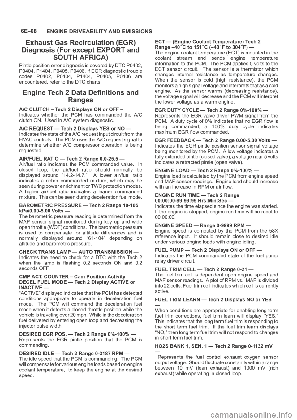
Exhaust Gas Recirculation (EGR)
Diagnosis (For except EXPORT and
SOUTH AFRICA)
Pintle position error diagnosis is covered by DTC P0402,
P0404, P1404, P0405, P0406. If EGR diagnostic trouble
codes P0402, P0404, P1404, P0405, P0406 are
encountered, refer to the DTC charts.
Engine Tech 2 Data Definitions and
Ranges
A/C CLUTCH – Tech 2 Displays ON or OFF –
Indicates whether the PCM has commanded the A/C
clutch ON. Used in A/C system diagnostic.
A/C REQUEST — Tech 2 Displays YES or NO —
Indicates the state of the A/C request input circuit from the
HVAC controls. The PCM uses the A/C request signal to
determine whether A/C compressor operation is being
requested.
AIR/FUEL RATIO — Tech 2 Range 0.0-25.5 —
Air/fuel ratio indicates the PCM commanded value. In
closed loop, the air/fuel ratio should normally be
displayed around “14.2-14.7.” A lower air/fuel ratio
indicates a richer commanded mixture, which may be
seen during power enrichment or TWC protection modes.
A higher air/fuel ratio indicates a leaner commanded
mixture. This can be seen during deceleration fuel mode.
BAROMETRIC PRESSURE — Tech 2 Range 10-105
kPa/0.00-5.00 Volts —
The barometric pressure reading is determined from the
MAP sensor signal monitored during key up and wide
open throttle (WOT) conditions. The barometric pressure
is used to compensate for altitude differences and is
normally displayed around “61-104” depending on
altitude and barometric pressure.
CHECK TRANS LAMP — AUTO TRANSMISSION —
Indicates the need to check for a DTC with the Tech 2
when the lamp is flashing 0.2 seconds ON and 0.2
seconds OFF.
CMP ACT. COUNTER – Cam Position Activity
DECEL FUEL MODE — Tech 2 Display ACTIVE or
INACTIVE —
“ACTIVE” displayed indicates that the PCM has detected
conditions appropriate to operate in deceleration fuel
mode. The PCM will command the deceleration fuel
mode when it detects a closed throttle position while the
vehicle is traveling over 20 mph. While in the deceleration
fuel delivered by entering open loop and decreasing the
injector pulse width.
DESIRED EGR POS. — Tech 2 Range 0%-100% —
Represents the EGR pintle position that the PCM is
commanding.
DESIRED IDLE — Tech 2 Range 0-3187 RPM —
The idle speed that the PCM is commanding. The PCM
will compensate for various engine loads based on engine
coolant temperature, to keep the engine at the desired
speed.ECT — (Engine Coolant Temperature) Tech 2
Range –40
C to 151C (–40F to 304F) —
The engine coolant temperature (ECT) is mounted in the
coolant stream and sends engine temperature
information to the PCM. The PCM applies 5 volts to the
ECT sensor circuit. The sensor is a thermistor which
changes internal resistance as temperature changes.
When the sensor is cold (high resistance), the PCM
monitors a high signal voltage and interprets that as a cold
engine. As the sensor warms (decreasing resistance),
the voltage signal will decrease and the PCM will interpret
the lower voltage as a warm engine.
EGR DUTY CYCLE — Tech 2 Range 0%-100% —
Represents the EGR valve driver PWM signal from the
PCM. A duty cycle of 0% indicates that no EGR flow is
being commanded; a 100% duty cycle indicates
maximum EGR flow commanded.
EGR FEEDBACK — Tech 2 Range 0.00-5.00 Volts —
Indicates the EGR pintle position sensor signal voltage
being monitored by the PCM. A low voltage indicates a
fully extended pintle (closed valve); a voltage near 5 volts
indicates a retracted pintle (open valve).
ENGINE LOAD — Tech 2 Range 0%-100% —
Engine load is calculated by the PCM from engine speed
and MAF sensor readings. Engine load should increase
with an increase in RPM or air flow.
ENGINE RUN TIME — Tech 2 Range
00:00:00-99:99:99 Hrs:Min:Sec —
Indicates the time elapsed since the engine was started.
If the engine is stopped, engine run time will be reset to
00:00:00.
ENGINE SPEED — Range 0-9999 RPM —
Engine speed is computed by the PCM from the 58X
reference input. It should remain close to desired idle
under various engine loads with engine idling.
FUEL PUMP — Tech 2 Displays ON or OFF —
Indicates the PCM commanded state of the fuel pump
relay driver circuit.
FUEL TRIM CELL — Tech 2 Range 0-21 —
The fuel trim cell is dependent upon engine speed and
MAF sensor readings. A plot of RPM vs. MAF is divided
into 22 cells. Fuel trim cell indicates which cell is currently
active.
FUEL TRIM LEARN — Tech 2 Displays NO or YES
—
When conditions are appropriate for enabling long term
fuel trim corrections, fuel trim learn will display “YES.”
This indicates that the long term fuel trim is responding to
the short term fuel trim. If the fuel trim learn displays
“NO,” then long term fuel trim will not respond to changes
in short term fuel trim.
HO2S BANK 1, SEN. 1 — Tech 2 Range 0-1132 mV
—
Represents the fuel control exhaust oxygen sensor
output voltage. Should fluctuate constantly within a range
between 10 mV (lean exhaust) and 1000 mV (rich
exhaust) while operating in closed loop.
Page 1186 of 6000
6E–69 ENGINE DRIVEABILITY AND EMISSIONS
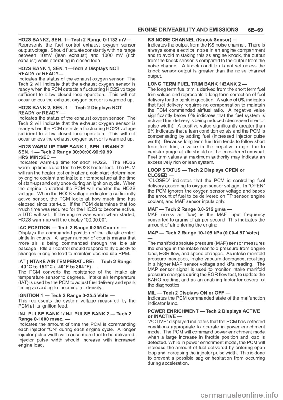
HO2S BANK2, SEN. 1—Tech 2 Range 0-1132 mV—
Represents the fuel control exhaust oxygen sensor
output voltage. Should fluctuate constantly within a range
between 10mV (lean exhaust) and 1000 mV (rich
exhaust) while operating in closed loop.
HO2S BANK 1, SEN. 1—Tech 2 Displays NOT
READY or READY—
Indicates the status of the exhaust oxygen sensor. The
Tech 2 will indicate that the exhaust oxygen sensor is
ready when the PCM detects a fluctuating HO2S voltage
sufficient to allow closed loop operation. This will not
occur unless the exhaust oxygen sensor is warmed up.
HO2S BANK 2, SEN. 1 — Tech 2 Displays NOT
READY or READY —
Indicates the status of the exhaust oxygen sensor. The
Tech 2 will indicate that the exhaust oxygen sensor is
ready when the PCM detects a fluctuating HO2S voltage
sufficient to allow closed loop operation. This will not
occur unless the exhaust oxygen sensor is warmed up.
HO2S WARM UP TIME BANK 1, SEN. 1/BANK 2
SEN. 1 — Tech 2 Range 00:00:00-99:99:99
HRS:MIN:SEC —
Indicates warm-up time for each HO2S. The HO2S
warm-up time is used for the HO2S heater test. The PCM
will run the heater test only after a cold start (determined
by engine coolant and intake air temperature at the time
of start-up) and only once during an ignition cycle. When
the engine is started the PCM will monitor the HO2S
voltage. When the HO2S voltage indicates a sufficiently
active sensor, the PCM looks at how much time has
elapsed since start-up. If the PCM determines that too
much time was required for the HO2S to become active,
a DTC will set. If the engine was warm when started,
HO2S warm-up will the display “00:00:00”.
IAC POSITION — Tech 2 Range 0-255 Counts —
Displays the commanded position of the idle air control
pintle in counts. A larger number of counts means that
more air is being commanded through the idle air
passage. Idle air control should respond fairly quickly to
changes in engine load to maintain desired idle RPM.
IAT (INTAKE AIR TEMPERATURE) — Tech 2 Range
–40
C to 151C (–40F to 304F) —
The PCM converts the resistance of the intake air
temperature sensor to degrees. Intake air temperature
(IAT) is used by the PCM to adjust fuel delivery and spark
timing according to incoming air density.
IGNITION 1 — Tech 2 Range 0-25.5 Volts —
This represents the system voltage measured by the
PCM at its ignition feed.
INJ. PULSE BANK 1/INJ. PULSE BANK 2 — Tech 2
Range 0-1000 msec. —
Indicates the amount of time the PCM is commanding
each injector “ON” during each engine cycle. A longer
injector pulse width will cause more fuel to be delivered.
Injector pulse width should increase with increased
engine load.KS NOISE CHANNEL (Knock Sensor) —
Indicates the output from the KS noise channel. There is
always some electrical noise in an engine compartment
and to avoid mistaking this as engine knock, the output
from the knock sensor is compared to the output from the
noise channel. A knock condition is not set unless the
knock sensor output is greater than the noise channel
output.
LONG TERM FUEL TRIM BANK 1/BANK 2 —
The long term fuel trim is derived from the short term fuel
trim values and represents a long term correction of fuel
delivery for the bank in question. A value of 0% indicates
that fuel delivery requires no compensation to maintain
the PCM commanded air/fuel ratio. A negative value
significantly below 0% indicates that the fuel system is
rich and fuel delivery is being reduced (decreased injector
pulse width). A positive value significantly greater than
0% indicates that a lean condition exists and the PCM is
compensating by adding fuel (increased injector pulse
width). Because long term fuel trim tends to follow short
term fuel trim, a value in the negative range due to
canister purge at idle should not be considered unusual.
Fuel trim values at maximum authority may indicate an
excessively rich or lean system.
LOOP STATUS — Tech 2 Displays OPEN or
CLOSED —
“CLOSED” indicates that the PCM is controlling fuel
delivery according to oxygen sensor voltage. In “OPEN”
the PCM ignores the oxygen sensor voltage and bases
the amount of fuel to be delivered on TP sensor, engine
coolant, and MAF sensor inputs only.
MAF — Tech 2 Range 0.0-512 gm/s —
MAF (mass air flow) is the MAF input frequency
converted to grams of air per second. This indicates the
amount of air entering the engine.
MAP — Tech 2 Range 10-105 kPa (0.00-4.97 Volts)
—
The manifold absolute pressure (MAP) sensor measures
the change in the intake manifold pressure from engine
load, EGR flow, and speed changes. As intake manifold
pressure increases, intake vacuum decreases, resulting
in a higher MAP sensor voltage and kPa reading. The
MAP sensor signal is used to monitor intake manifold
pressure changes during the EGR flow test, to update the
BARO reading, and as an enabling factor for several of
the diagnostics.
MIL — Tech 2 Displays ON or OFF —
Indicates the PCM commanded state of the malfunction
indicator lamp.
POWER ENRICHMENT — Tech 2 Displays ACTIVE
or INACTIVE —
“ACTIVE” displayed indicates that the PCM has detected
conditions appropriate to operate in power enrichment
mode. The PCM will command power enrichment mode
when a large increase in throttle position and load is
detected. While in power enrichment mode, the PCM will
increase the amount of fuel delivered by entering open
loop and increasing the injector pulse width. This is done
to prevent a possible sag or hesitation from occurring
during acceleration.
Page 1224 of 6000
6E–107 ENGINE DRIVEABILITY AND EMISSIONS
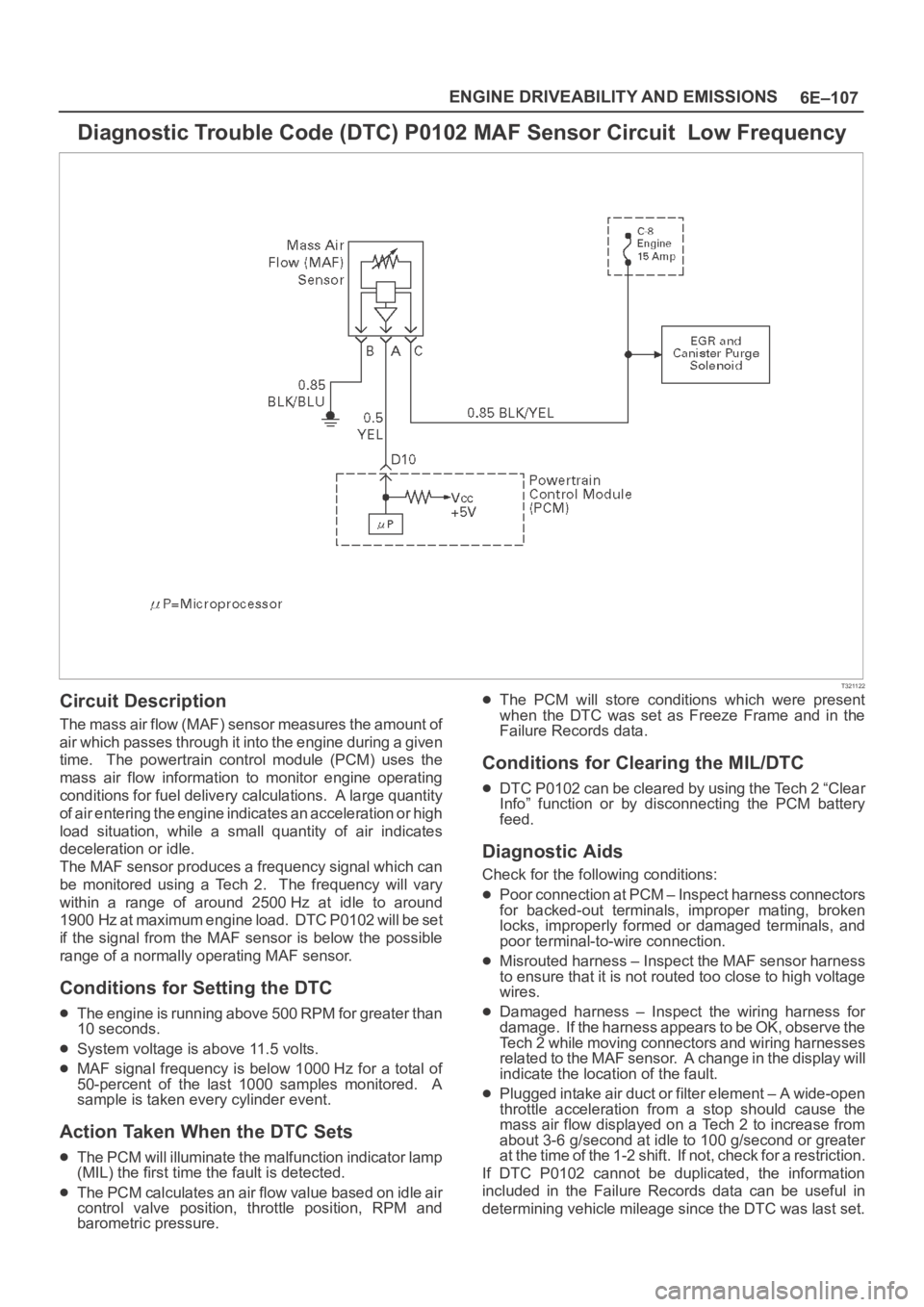
Diagnostic Trouble Code (DTC) P0102 MAF Sensor Circuit Low Frequency
T321122
Circuit Description
The mass air flow (MAF) sensor measures the amount of
air which passes through it into the engine during a given
time. The powertrain control module (PCM) uses the
mass air flow information to monitor engine operating
conditions for fuel delivery calculations. A large quantity
of air entering the engine indicates an acceleration or high
load situation, while a small quantity of air indicates
deceleration or idle.
The MAF sensor produces a frequency signal which can
be monitored using a Tech 2. The frequency will vary
within a range of around 2500 Hz at idle to around
1900 Hz at maximum engine load. DTC P0102 will be set
if the signal from the MAF sensor is below the possible
range of a normally operating MAF sensor.
Conditions for Setting the DTC
The engine is running above 500 RPM for greater than
10 seconds.
System voltage is above 11.5 volts.
MAF signal frequency is below 1000 Hz for a total of
50-percent of the last 1000 samples monitored. A
sample is taken every cylinder event.
Action Taken When the DTC Sets
The PCM will illuminate the malfunction indicator lamp
(MIL) the first time the fault is detected.
The PCM calculates an air flow value based on idle air
control valve position, throttle position, RPM and
barometric pressure.
The PCM will store conditions which were present
when the DTC was set as Freeze Frame and in the
Failure Records data.
Conditions for Clearing the MIL/DTC
DTC P0102 can be cleared by using the Tech 2 “Clear
Info” function or by disconnecting the PCM battery
feed.
Diagnostic Aids
Check for the following conditions:
Poor connection at PCM – Inspect harness connectors
for backed-out terminals, improper mating, broken
locks, improperly formed or damaged terminals, and
poor terminal-to-wire connection.
Misrouted harness – Inspect the MAF sensor harness
to ensure that it is not routed too close to high voltage
wires.
Damaged harness – Inspect the wiring harness for
damage. If the harness appears to be OK, observe the
Tech 2 while moving connectors and wiring harnesses
related to the MAF sensor. A change in the display will
indicate the location of the fault.
Plugged intake air duct or filter element – A wide-open
throttle acceleration from a stop should cause the
mass air flow displayed on a Tech 2 to increase from
about 3-6 g/second at idle to 100 g/second or greater
at the time of the 1-2 shift. If not, check for a restriction.
If DTC P0102 cannot be duplicated, the information
included in the Failure Records data can be useful in
determining vehicle mileage since the DTC was last set.
Page 1229 of 6000
6E–112
ENGINE DRIVEABILITY AND EMISSIONS
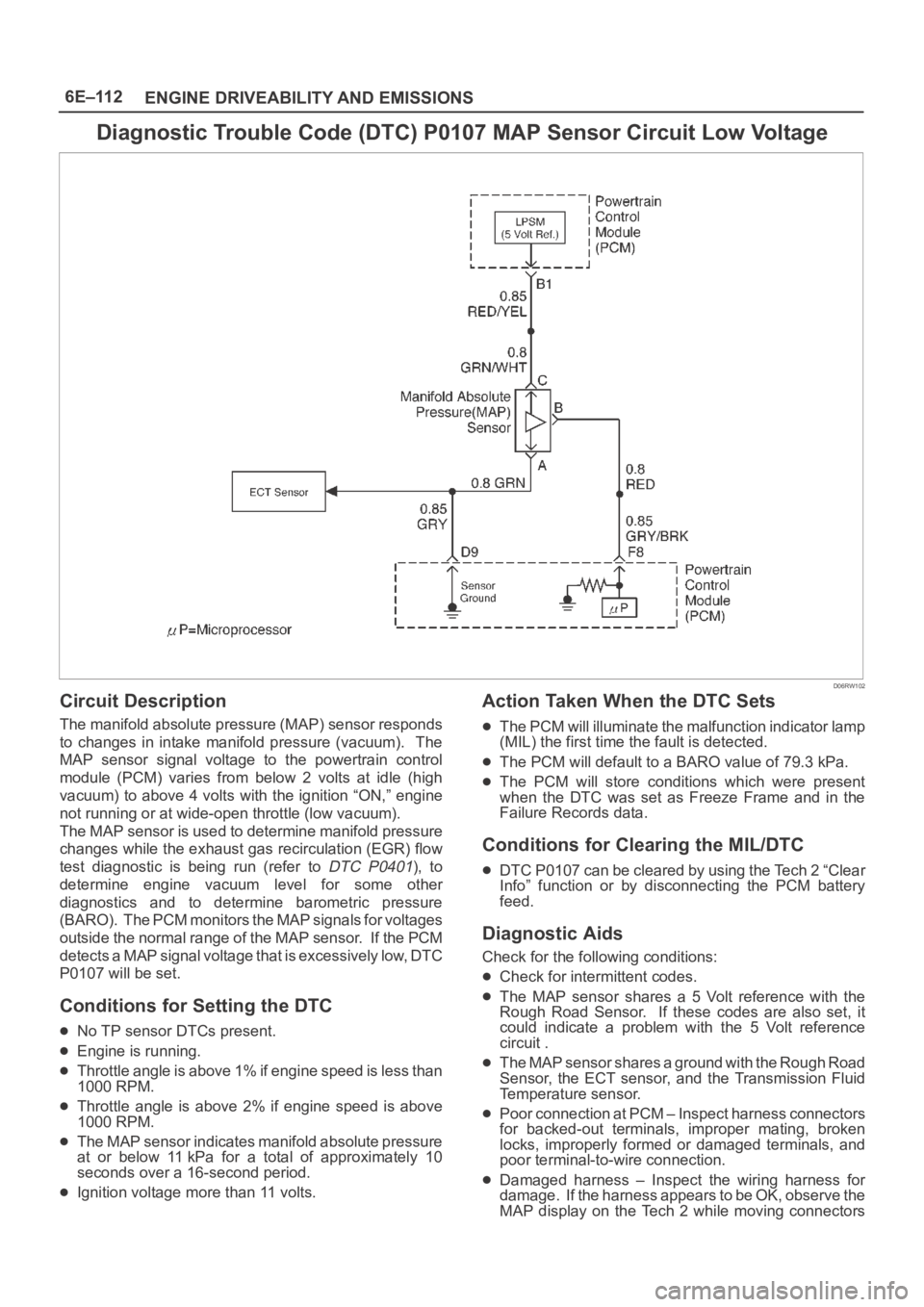
Diagnostic Trouble Code (DTC) P0107 MAP Sensor Circuit Low Voltage
D06RW102
Circuit Description
The manifold absolute pressure (MAP) sensor responds
to changes in intake manifold pressure (vacuum). The
MAP sensor signal voltage to the powertrain control
module (PCM) varies from below 2 volts at idle (high
vacuum) to above 4 volts with the ignition “ON,” engine
not running or at wide-open throttle (low vacuum).
The MAP sensor is used to determine manifold pressure
changes while the exhaust gas recirculation (EGR) flow
test diagnostic is being run (refer to
DTC P0401), to
determine engine vacuum level for some other
diagnostics and to determine barometric pressure
(BARO). The PCM monitors the MAP signals for voltages
outside the normal range of the MAP sensor. If the PCM
detects a MAP signal voltage that is excessively low, DTC
P0107 will be set.
Conditions for Setting the DTC
No TP sensor DTCs present.
Engine is running.
Throttle angle is above 1% if engine speed is less than
1000 RPM.
Throttle angle is above 2% if engine speed is above
1000 RPM.
The MAP sensor indicates manifold absolute pressure
at or below 11 kPa for a total of approximately 10
seconds over a 16-second period.
Ignition voltage more than 11 volts.
Action Taken When the DTC Sets
The PCM will illuminate the malfunction indicator lamp
(MIL) the first time the fault is detected.
The PCM will default to a BARO value of 79.3 kPa.
The PCM will store conditions which were present
when the DTC was set as Freeze Frame and in the
Failure Records data.
Conditions for Clearing the MIL/DTC
DTC P0107 can be cleared by using the Tech 2 “Clear
Info” function or by disconnecting the PCM battery
feed.
Diagnostic Aids
Check for the following conditions:
Check for intermittent codes.
The MAP sensor shares a 5 Volt reference with the
Rough Road Sensor. If these codes are also set, it
could indicate a problem with the 5 Volt reference
circuit .
The MAP sensor shares a ground with the Rough Road
Sensor, the ECT sensor, and the Transmission Fluid
Temperature sensor.
Poor connection at PCM – Inspect harness connectors
for backed-out terminals, improper mating, broken
locks, improperly formed or damaged terminals, and
poor terminal-to-wire connection.
Damaged harness – Inspect the wiring harness for
damage. If the harness appears to be OK, observe the
MAP display on the Tech 2 while moving connectors
Page 1232 of 6000
6E–115 ENGINE DRIVEABILITY AND EMISSIONS
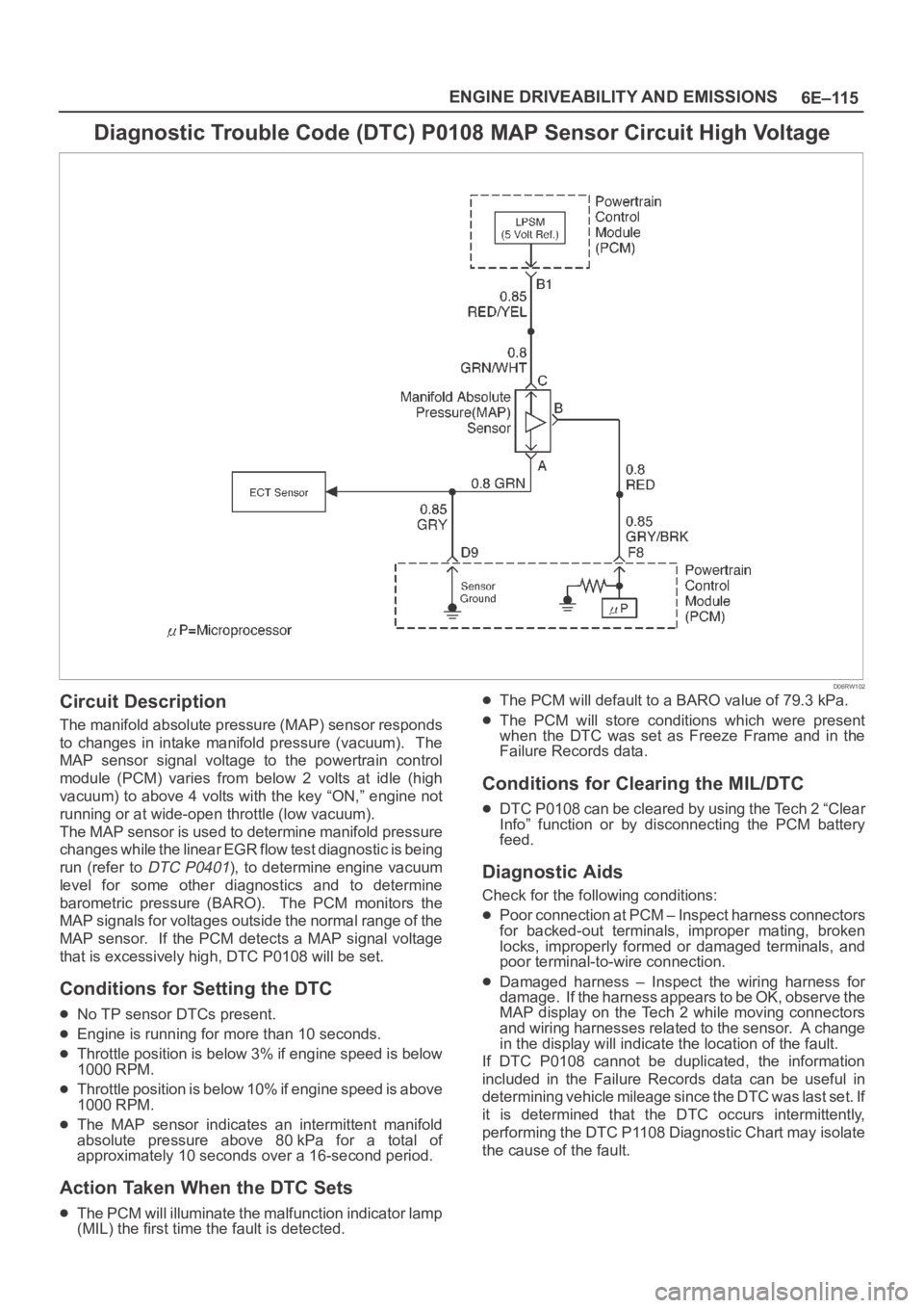
Diagnostic Trouble Code (DTC) P0108 MAP Sensor Circuit High Voltage
D06RW102
Circuit Description
The manifold absolute pressure (MAP) sensor responds
to changes in intake manifold pressure (vacuum). The
MAP sensor signal voltage to the powertrain control
module (PCM) varies from below 2 volts at idle (high
vacuum) to above 4 volts with the key “ON,” engine not
running or at wide-open throttle (low vacuum).
The MAP sensor is used to determine manifold pressure
changes while the linear EGR flow test diagnostic is being
run (refer to
DTC P0401), to determine engine vacuum
level for some other diagnostics and to determine
barometric pressure (BARO). The PCM monitors the
MAP signals for voltages outside the normal range of the
MAP sensor. If the PCM detects a MAP signal voltage
that is excessively high, DTC P0108 will be set.
Conditions for Setting the DTC
No TP sensor DTCs present.
Engine is running for more than 10 seconds.
Throttle position is below 3% if engine speed is below
1000 RPM.
Throttle position is below 10% if engine speed is above
1000 RPM.
The MAP sensor indicates an intermittent manifold
absolute pressure above 80kPa for a total of
approximately 10 seconds over a 16-second period.
Action Taken When the DTC Sets
The PCM will illuminate the malfunction indicator lamp
(MIL) the first time the fault is detected.
The PCM will default to a BARO value of 79.3 kPa.
The PCM will store conditions which were present
when the DTC was set as Freeze Frame and in the
Failure Records data.
Conditions for Clearing the MIL/DTC
DTC P0108 can be cleared by using the Tech 2 “Clear
Info” function or by disconnecting the PCM battery
feed.
Diagnostic Aids
Check for the following conditions:
Poor connection at PCM – Inspect harness connectors
for backed-out terminals, improper mating, broken
locks, improperly formed or damaged terminals, and
poor terminal-to-wire connection.
Damaged harness – Inspect the wiring harness for
damage. If the harness appears to be OK, observe the
MAP display on the Tech 2 while moving connectors
and wiring harnesses related to the sensor. A change
in the display will indicate the location of the fault.
If DTC P0108 cannot be duplicated, the information
included in the Failure Records data can be useful in
determining vehicle mileage since the DTC was last set. If
it is determined that the DTC occurs intermittently,
performing the DTC P1108 Diagnostic Chart may isolate
the cause of the fault.
Page 1256 of 6000
6E–139 ENGINE DRIVEABILITY AND EMISSIONS
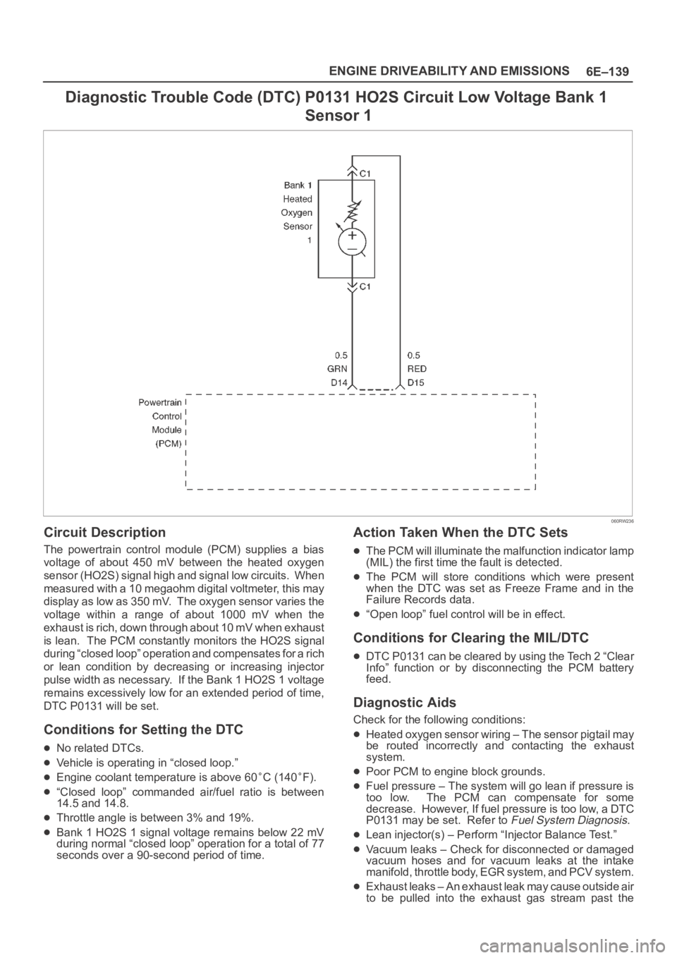
Diagnostic Trouble Code (DTC) P0131 HO2S Circuit Low Voltage Bank 1
Sensor 1
060RW236
Circuit Description
The powertrain control module (PCM) supplies a bias
voltage of about 450 mV between the heated oxygen
sensor (HO2S) signal high and signal low circuits. When
measured with a 10 megaohm digital voltmeter, this may
display as low as 350 mV. The oxygen sensor varies the
voltage within a range of about 1000 mV when the
exhaust is rich, down through about 10 mV when exhaust
is lean. The PCM constantly monitors the HO2S signal
during “closed loop” operation and compensates for a rich
or lean condition by decreasing or increasing injector
pulse width as necessary. If the Bank 1 HO2S 1 voltage
remains excessively low for an extended period of time,
DTC P0131 will be set.
Conditions for Setting the DTC
No related DTCs.
Vehicle is operating in “closed loop.”
Engine coolant temperature is above 60C (140F).
“Closed loop” commanded air/fuel ratio is between
14.5 and 14.8.
Throttle angle is between 3% and 19%.
Bank 1 HO2S 1 signal voltage remains below 22 mV
during normal “closed loop” operation for a total of 77
seconds over a 90-second period of time.
Action Taken When the DTC Sets
The PCM will illuminate the malfunction indicator lamp
(MIL) the first time the fault is detected.
The PCM will store conditions which were present
when the DTC was set as Freeze Frame and in the
Failure Records data.
“Open loop” fuel control will be in effect.
Conditions for Clearing the MIL/DTC
DTC P0131 can be cleared by using the Tech 2 “Clear
Info” function or by disconnecting the PCM battery
feed.
Diagnostic Aids
Check for the following conditions:
Heated oxygen sensor wiring – The sensor pigtail may
be routed incorrectly and contacting the exhaust
system.
Poor PCM to engine block grounds.
Fuel pressure – The system will go lean if pressure is
too low. The PCM can compensate for some
decrease. However, If fuel pressure is too low, a DTC
P0131 may be set. Refer to
Fuel System Diagnosis.
Lean injector(s) – Perform “Injector Balance Test.”
Vacuum leaks – Check for disconnected or damaged
vacuum hoses and for vacuum leaks at the intake
manifold, throttle body, EGR system, and PCV system.
Exhaust leaks – An exhaust leak may cause outside air
to be pulled into the exhaust gas stream past the