1998 OPEL FRONTERA Gas
[x] Cancel search: GasPage 1208 of 6000
6E–91 ENGINE DRIVEABILITY AND EMISSIONS
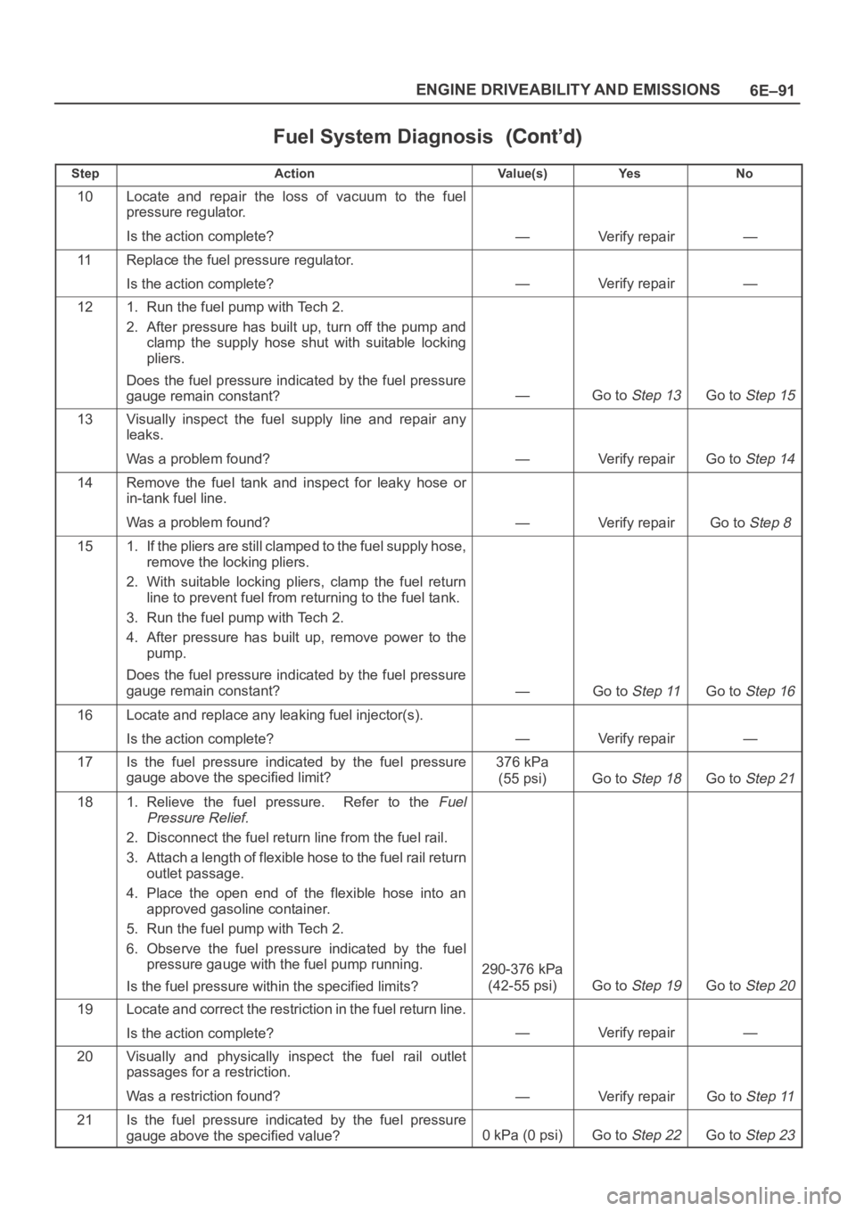
Fuel System Diagnosis
StepNo Ye s Va l u e ( s ) Action
10Locate and repair the loss of vacuum to the fuel
pressure regulator.
Is the action complete?
—Verify repair—
11Replace the fuel pressure regulator.
Is the action complete?
—Verify repair—
121. Run the fuel pump with Tech 2.
2. After pressure has built up, turn off the pump and
clamp the supply hose shut with suitable locking
pliers.
Does the fuel pressure indicated by the fuel pressure
gauge remain constant?
—Go to Step 13Go to Step 15
13Visually inspect the fuel supply line and repair any
leaks.
Was a problem found?
—Verify repairGo to Step 14
14Remove the fuel tank and inspect for leaky hose or
in-tank fuel line.
Was a problem found?
—Verify repairGo to Step 8
151. If the pliers are still clamped to the fuel supply hose,
remove the locking pliers.
2. With suitable locking pliers, clamp the fuel return
line to prevent fuel from returning to the fuel tank.
3. Run the fuel pump with Tech 2.
4. After pressure has built up, remove power to the
pump.
Does the fuel pressure indicated by the fuel pressure
gauge remain constant?
—Go to Step 11Go to Step 16
16Locate and replace any leaking fuel injector(s).
Is the action complete?
—Verify repair—
17Is the fuel pressure indicated by the fuel pressure
gauge above the specified limit?376 kPa
(55 psi)
Go to Step 18Go to Step 21
181. Relieve the fuel pressure. Refer to the Fuel
Pressure Relief.
2. Disconnect the fuel return line from the fuel rail.
3. Attach a length of flexible hose to the fuel rail return
outlet passage.
4. Place the open end of the flexible hose into an
approved gasoline container.
5. Run the fuel pump with Tech 2.
6. Observe the fuel pressure indicated by the fuel
pressure gauge with the fuel pump running.
Is the fuel pressure within the specified limits?
290-376 kPa
(42-55 psi)
Go to Step 19Go to Step 20
19Locate and correct the restriction in the fuel return line.
Is the action complete?
—Verify repair—
20Visually and physically inspect the fuel rail outlet
passages for a restriction.
Was a restriction found?
—Verify repairGo to Step 11
21Is the fuel pressure indicated by the fuel pressure
gauge above the specified value?
0kPa (0psi)Go to Step 22Go to Step 23
Page 1214 of 6000
6E–97 ENGINE DRIVEABILITY AND EMISSIONS
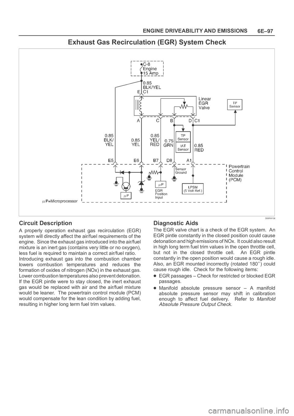
Exhaust Gas Recirculation (EGR) System Check
D06RW106
Circuit Description
A properly operation exhaust gas recirculation (EGR)
system will directly affect the air/fuel requirements of the
engine. Since the exhaust gas introduced into the air/fuel
mixture is an inert gas (contains very little or no oxygen),
less fuel is required to maintain a correct air/fuel ratio.
Introducing exhaust gas into the combustion chamber
lowers combustion temperatures and reduces the
formation of oxides of nitrogen (NOx) in the exhaust gas.
Lower combustion temperatures also prevent detonation.
If the EGR pintle were to stay closed, the inert exhaust
gas would be replaced with air and the air/fuel mixture
would be leaner. The powertrain control module (PCM)
would compensate for the lean condition by adding fuel,
resulting in higher long term fuel trim values.
Diagnostic Aids
The EGR valve chart is a check of the EGR system. An
EGR pintle constantly in the closed position could cause
detonation and high emissions of NOx. It could also result
in high long term fuel trim values in the open throttle cell,
but not in the closed throttle cell. An EGR pintle
constantly in the open position would cause a rough idle.
Also, an EGR mounted incorrectly (rotated 180
) could
cause rough idle. Check for the following items:
EGR passages – Check for restricted or blocked EGR
passages.
Manifold absolute pressure sensor – A manifold
absolute pressure sensor may shift in calibration
enough to affect fuel delivery. Refer to
Manifold
Absolute Pressure Output Check.
Page 1215 of 6000

6E–98
ENGINE DRIVEABILITY AND EMISSIONS
Exhaust Gas Recirculation (EGR) System Check
StepActionVa l u e ( s )Ye sNo
1Check the EGR valve for looseness.
Is the EGR valve Loose?
—Go to Step 2Go to Step 3
2Tighten the EGR valve.
Is the action complete?
—Verify repair—
31. Place the transmission selector in Park or Neutral.
2. Start the engine and idle until warm.
3. Using Tech 2, command EGR “50% ON.”
Does the engine idle rough and lose RPMs?
—
EGR system
working
properly. No
problem
found.
Go to Step 4
41. Engine “OFF.”
2. Ignition “ON.”
3. Using a test light to ground, check the EGR harness
between the EGR valve and the ignition feed.
Does the test light illuminate?
—Go to Step 6Go to Step 5
5Repair the EGR harness ignition feed.
Was the problem corrected?
—Verify repairGo to Step 6
61. Remove the EGR valve.
2. Visually and physically inspect the EGR valve
pintle, valve passages and adapter for excessive
deposits, obstructions or any restrictions.
Does the EGR valve have excessive deposits,
obstructions or any restrictions?
—Go to Step 7Go to Step 8
7Clean or replace EGR system components as
necessary.
Was the problem corrected?
—Verify repairGo to Step 8
81. Ground the EGR valve metal case to battery (–).
2. Using Tech 2, command EGR “ON” and observe the
EGR valve pintle for movement.
Does the EGR valve pintle move according to
command?
—Go to Step 9
Go to DTC
P1406 chart
91. Remove the EGR inlet and outlet pipes from the
intake and exhaust manifolds.
2. Visually and physically inspect manifold EGR ports
and EGR inlet and outlet pipes for blockage or
restriction caused by excessive deposits or other
damage.
Do the manifold EGR ports or inlet and outlet pipes
have excessive deposits, obstructions, or any
restrictions?
—Go to Step 10
EGR system
working
properly. No
problem
found.
10Clean or replace EGR system components as
necessary.
Is the action complete?
—Verify repair—
Page 1229 of 6000
6E–112
ENGINE DRIVEABILITY AND EMISSIONS
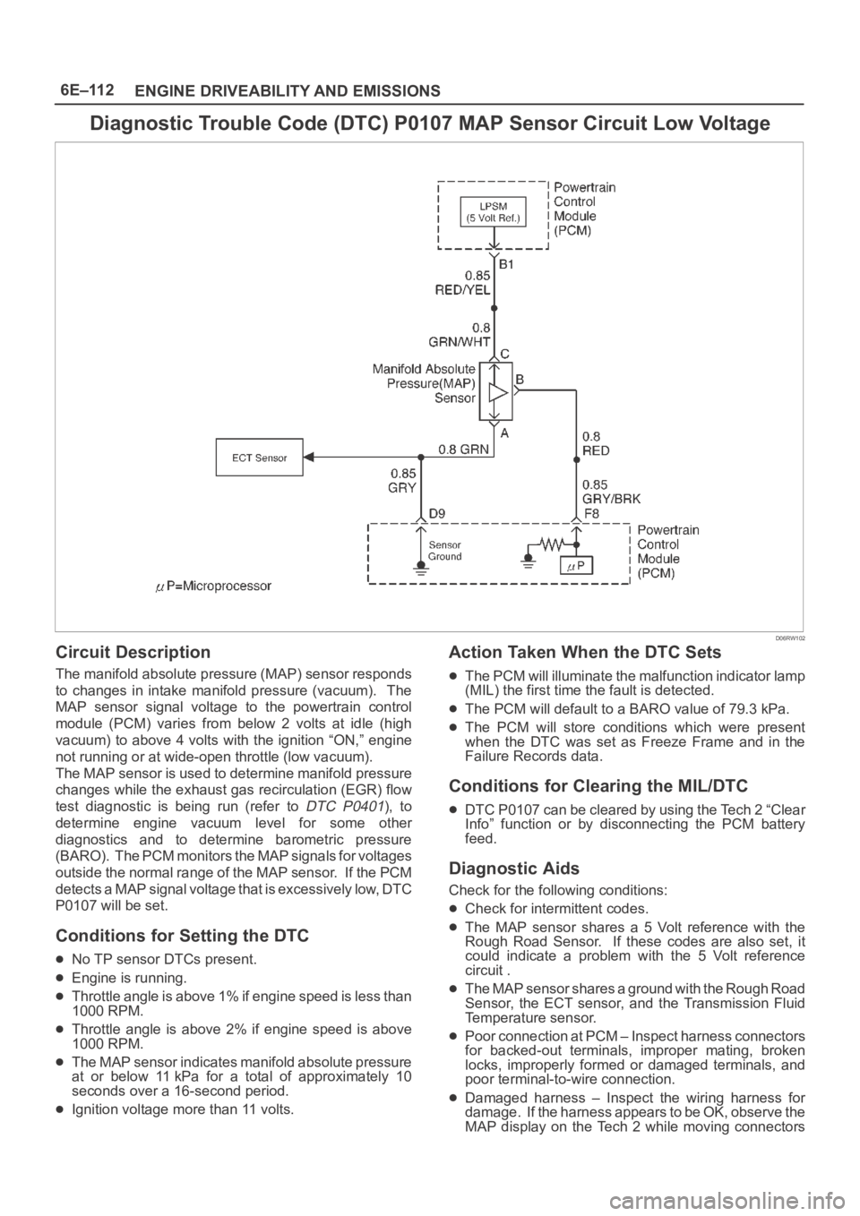
Diagnostic Trouble Code (DTC) P0107 MAP Sensor Circuit Low Voltage
D06RW102
Circuit Description
The manifold absolute pressure (MAP) sensor responds
to changes in intake manifold pressure (vacuum). The
MAP sensor signal voltage to the powertrain control
module (PCM) varies from below 2 volts at idle (high
vacuum) to above 4 volts with the ignition “ON,” engine
not running or at wide-open throttle (low vacuum).
The MAP sensor is used to determine manifold pressure
changes while the exhaust gas recirculation (EGR) flow
test diagnostic is being run (refer to
DTC P0401), to
determine engine vacuum level for some other
diagnostics and to determine barometric pressure
(BARO). The PCM monitors the MAP signals for voltages
outside the normal range of the MAP sensor. If the PCM
detects a MAP signal voltage that is excessively low, DTC
P0107 will be set.
Conditions for Setting the DTC
No TP sensor DTCs present.
Engine is running.
Throttle angle is above 1% if engine speed is less than
1000 RPM.
Throttle angle is above 2% if engine speed is above
1000 RPM.
The MAP sensor indicates manifold absolute pressure
at or below 11 kPa for a total of approximately 10
seconds over a 16-second period.
Ignition voltage more than 11 volts.
Action Taken When the DTC Sets
The PCM will illuminate the malfunction indicator lamp
(MIL) the first time the fault is detected.
The PCM will default to a BARO value of 79.3 kPa.
The PCM will store conditions which were present
when the DTC was set as Freeze Frame and in the
Failure Records data.
Conditions for Clearing the MIL/DTC
DTC P0107 can be cleared by using the Tech 2 “Clear
Info” function or by disconnecting the PCM battery
feed.
Diagnostic Aids
Check for the following conditions:
Check for intermittent codes.
The MAP sensor shares a 5 Volt reference with the
Rough Road Sensor. If these codes are also set, it
could indicate a problem with the 5 Volt reference
circuit .
The MAP sensor shares a ground with the Rough Road
Sensor, the ECT sensor, and the Transmission Fluid
Temperature sensor.
Poor connection at PCM – Inspect harness connectors
for backed-out terminals, improper mating, broken
locks, improperly formed or damaged terminals, and
poor terminal-to-wire connection.
Damaged harness – Inspect the wiring harness for
damage. If the harness appears to be OK, observe the
MAP display on the Tech 2 while moving connectors
Page 1256 of 6000
6E–139 ENGINE DRIVEABILITY AND EMISSIONS
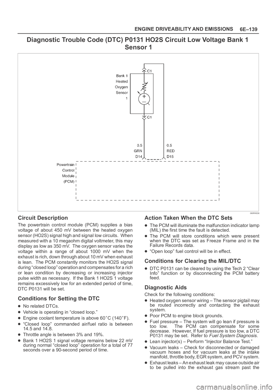
Diagnostic Trouble Code (DTC) P0131 HO2S Circuit Low Voltage Bank 1
Sensor 1
060RW236
Circuit Description
The powertrain control module (PCM) supplies a bias
voltage of about 450 mV between the heated oxygen
sensor (HO2S) signal high and signal low circuits. When
measured with a 10 megaohm digital voltmeter, this may
display as low as 350 mV. The oxygen sensor varies the
voltage within a range of about 1000 mV when the
exhaust is rich, down through about 10 mV when exhaust
is lean. The PCM constantly monitors the HO2S signal
during “closed loop” operation and compensates for a rich
or lean condition by decreasing or increasing injector
pulse width as necessary. If the Bank 1 HO2S 1 voltage
remains excessively low for an extended period of time,
DTC P0131 will be set.
Conditions for Setting the DTC
No related DTCs.
Vehicle is operating in “closed loop.”
Engine coolant temperature is above 60C (140F).
“Closed loop” commanded air/fuel ratio is between
14.5 and 14.8.
Throttle angle is between 3% and 19%.
Bank 1 HO2S 1 signal voltage remains below 22 mV
during normal “closed loop” operation for a total of 77
seconds over a 90-second period of time.
Action Taken When the DTC Sets
The PCM will illuminate the malfunction indicator lamp
(MIL) the first time the fault is detected.
The PCM will store conditions which were present
when the DTC was set as Freeze Frame and in the
Failure Records data.
“Open loop” fuel control will be in effect.
Conditions for Clearing the MIL/DTC
DTC P0131 can be cleared by using the Tech 2 “Clear
Info” function or by disconnecting the PCM battery
feed.
Diagnostic Aids
Check for the following conditions:
Heated oxygen sensor wiring – The sensor pigtail may
be routed incorrectly and contacting the exhaust
system.
Poor PCM to engine block grounds.
Fuel pressure – The system will go lean if pressure is
too low. The PCM can compensate for some
decrease. However, If fuel pressure is too low, a DTC
P0131 may be set. Refer to
Fuel System Diagnosis.
Lean injector(s) – Perform “Injector Balance Test.”
Vacuum leaks – Check for disconnected or damaged
vacuum hoses and for vacuum leaks at the intake
manifold, throttle body, EGR system, and PCV system.
Exhaust leaks – An exhaust leak may cause outside air
to be pulled into the exhaust gas stream past the
Page 1265 of 6000
6E–148
ENGINE DRIVEABILITY AND EMISSIONS
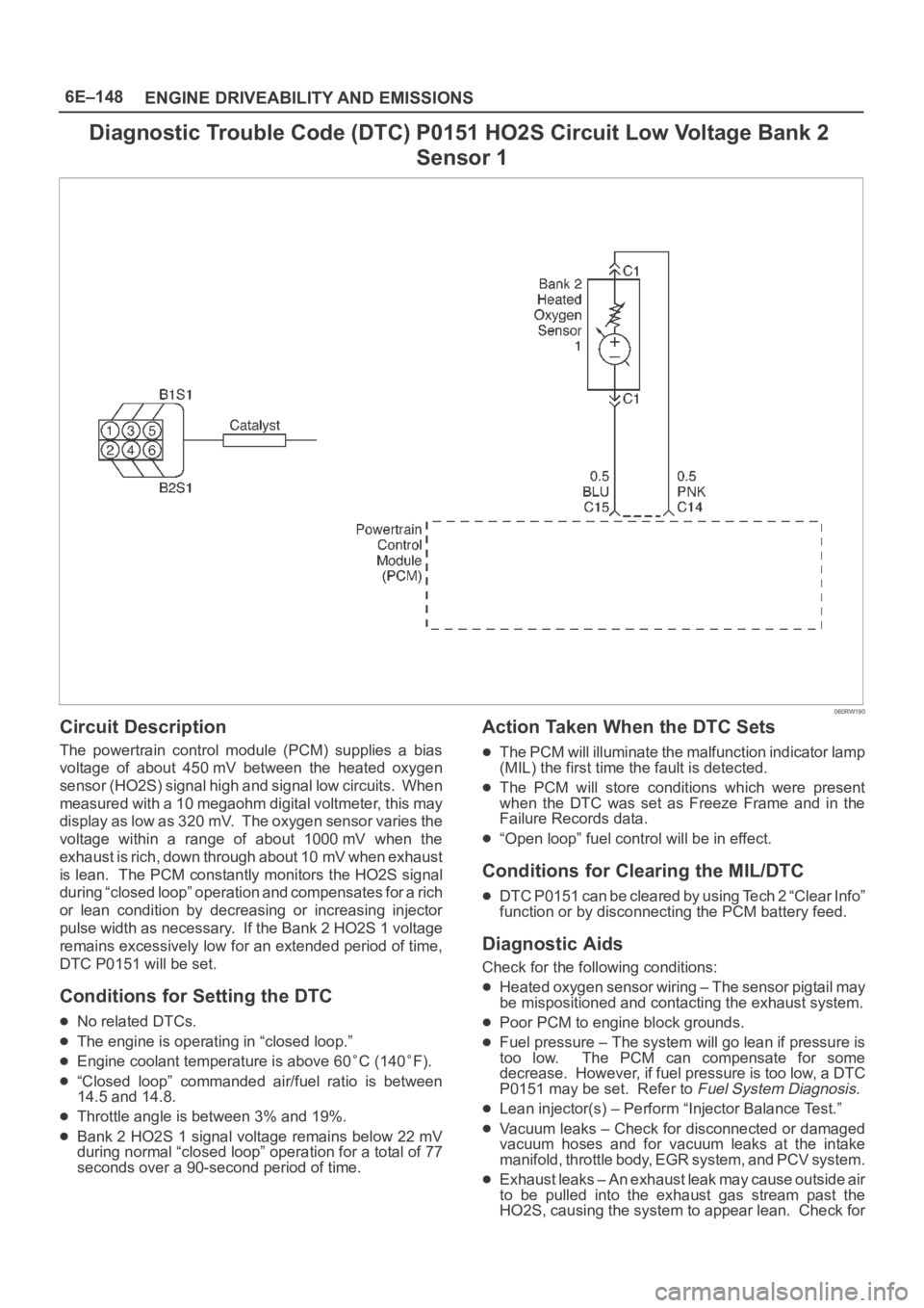
Diagnostic Trouble Code (DTC) P0151 HO2S Circuit Low Voltage Bank 2
Sensor 1
060RW190
Circuit Description
The powertrain control module (PCM) supplies a bias
voltage of about 450 mV between the heated oxygen
sensor (HO2S) signal high and signal low circuits. When
measured with a 10 megaohm digital voltmeter, this may
display as low as 320 mV. The oxygen sensor varies the
voltage within a range of about 1000 mV when the
exhaust is rich, down through about 10 mV when exhaust
is lean. The PCM constantly monitors the HO2S signal
during “closed loop” operation and compensates for a rich
or lean condition by decreasing or increasing injector
pulse width as necessary. If the Bank 2 HO2S 1 voltage
remains excessively low for an extended period of time,
DTC P0151 will be set.
Conditions for Setting the DTC
No related DTCs.
The engine is operating in “closed loop.”
Engine coolant temperature is above 60C (140F).
“Closed loop” commanded air/fuel ratio is between
14.5 and 14.8.
Throttle angle is between 3% and 19%.
Bank 2 HO2S 1 signal voltage remains below 22 mV
during normal “closed loop” operation for a total of 77
seconds over a 90-second period of time.
Action Taken When the DTC Sets
The PCM will illuminate the malfunction indicator lamp
(MIL) the first time the fault is detected.
The PCM will store conditions which were present
when the DTC was set as Freeze Frame and in the
Failure Records data.
“Open loop” fuel control will be in effect.
Conditions for Clearing the MIL/DTC
DTC P0151 can be cleared by using Tech 2 “Clear Info”
function or by disconnecting the PCM battery feed.
Diagnostic Aids
Check for the following conditions:
Heated oxygen sensor wiring – The sensor pigtail may
be mispositioned and contacting the exhaust system.
Poor PCM to engine block grounds.
Fuel pressure – The system will go lean if pressure is
too low. The PCM can compensate for some
decrease. However, if fuel pressure is too low, a DTC
P0151 may be set. Refer to
Fuel System Diagnosis.
Lean injector(s) – Perform “Injector Balance Test.”
Vacuum leaks – Check for disconnected or damaged
vacuum hoses and for vacuum leaks at the intake
manifold, throttle body, EGR system, and PCV system.
Exhaust leaks – An exhaust leak may cause outside air
to be pulled into the exhaust gas stream past the
HO2S, causing the system to appear lean. Check for
Page 1359 of 6000
6E–242
ENGINE DRIVEABILITY AND EMISSIONS
the condition that caused the DTC to be set occurs. This
may assist in diagnosing the condition.
Test Description
Number(s) below refer to the step number(s) on the
Diagnostic Chart.
3. A condition that affects other heated oxygen sensors
indicates probable contamination. To avoid
damaging replacement sensors, correct the
condition which caused the contamination before
replacing the affected sensors.5. This step checks for conditions which may cause the
heated oxygen sensor to appear faulty. Correct any
of the described conditions if present.
8. To avoid damaging replacement sensors, correct the
condition which caused the contamination before
replacing the affected sensors.
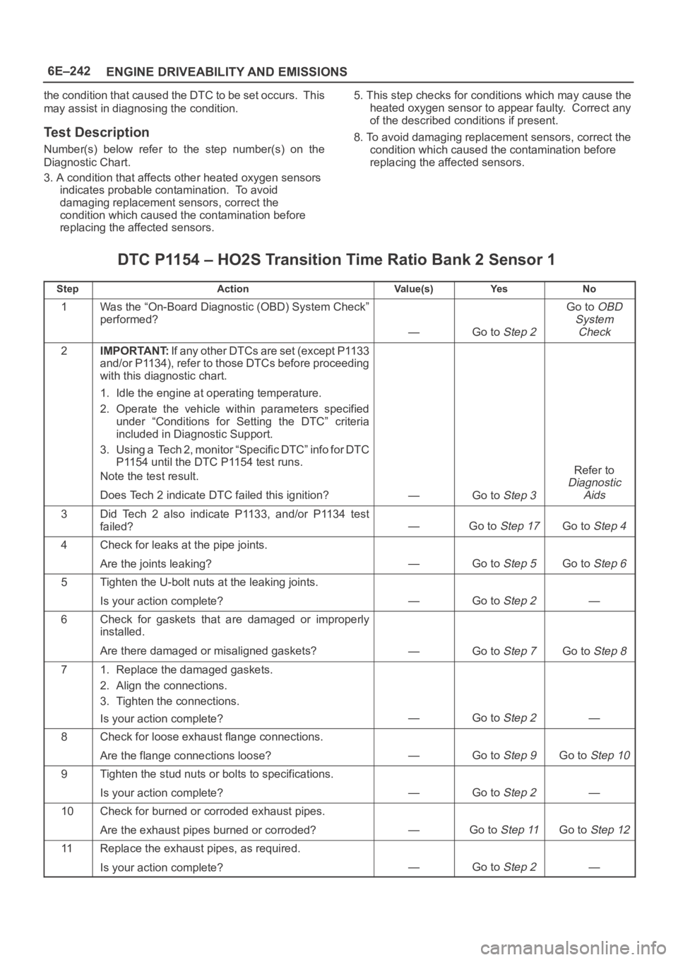
DTC P1154 – HO2S Transition Time Ratio Bank 2 Sensor 1
StepActionVa l u e ( s )Ye sNo
1Was the “On-Board Diagnostic (OBD) System Check”
performed?
—Go to Step 2
Go to OBD
System
Check
2IMPORTANT:If any other DTCs are set (except P1133
and/or P1134), refer to those DTCs before proceeding
with this diagnostic chart.
1. Idle the engine at operating temperature.
2. Operate the vehicle within parameters specified
under “Conditions for Setting the DTC” criteria
included in Diagnostic Support.
3. Using a Tech 2, monitor “Specific DTC” info for DTC
P1154 until the DTC P1154 test runs.
Note the test result.
Does Tech 2 indicate DTC failed this ignition?
—Go to Step 3
Refer to
Diagnostic
Aids
3Did Tech 2 also indicate P1133, and/or P1134 test
failed?
—Go to Step 17Go to Step 4
4Check for leaks at the pipe joints.
Are the joints leaking?
—Go to Step 5Go to Step 6
5Tighten the U-bolt nuts at the leaking joints.
Is your action complete?
—Go to Step 2—
6Check for gaskets that are damaged or improperly
installed.
Are there damaged or misaligned gaskets?
—Go to Step 7Go to Step 8
71. Replace the damaged gaskets.
2. Align the connections.
3. Tighten the connections.
Is your action complete?
—Go to Step 2—
8Check for loose exhaust flange connections.
Are the flange connections loose?
—Go to Step 9Go to Step 10
9Tighten the stud nuts or bolts to specifications.
Is your action complete?
—Go to Step 2—
10Check for burned or corroded exhaust pipes.
Are the exhaust pipes burned or corroded?
—Go to Step 11Go to Step 12
11Replace the exhaust pipes, as required.
Is your action complete?
—Go to Step 2—
Page 1381 of 6000
6E–264
ENGINE DRIVEABILITY AND EMISSIONS
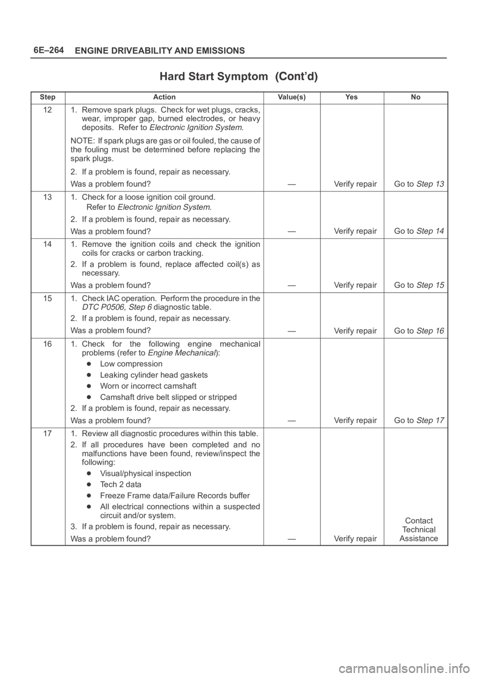
Hard Start Symptom
StepNo Ye s Va l u e ( s ) Action
121. Remove spark plugs. Check for wet plugs, cracks,
wear, improper gap, burned electrodes, or heavy
deposits. Refer to
Electronic Ignition System.
NOTE: If spark plugs are gas or oil fouled, the cause of
the fouling must be determined before replacing the
spark plugs.
2. If a problem is found, repair as necessary.
Was a problem found?
—Verify repairGo to Step 13
131. Check for a loose ignition coil ground.
Refer to
Electronic Ignition System.
2. If a problem is found, repair as necessary.
Was a problem found?
—Verify repairGo to Step 14
141. Remove the ignition coils and check the ignition
coils for cracks or carbon tracking.
2. If a problem is found, replace affected coil(s) as
necessary.
Was a problem found?
—Verify repairGo to Step 15
151. Check IAC operation. Perform the procedure in the
DTC P0506, Step 6 diagnostic table.
2. If a problem is found, repair as necessary.
Was a problem found?
—Verify repairGo to Step 16
161. Check for the following engine mechanical
problems (refer to
Engine Mechanical):
Low compression
Leaking cylinder head gaskets
Worn or incorrect camshaft
Camshaft drive belt slipped or stripped
2. If a problem is found, repair as necessary.
Was a problem found?
—Verify repairGo to Step 17
171. Review all diagnostic procedures within this table.
2. If all procedures have been completed and no
malfunctions have been found, review/inspect the
following:
Visual/physical inspection
Te c h 2 d a t a
Freeze Frame data/Failure Records buffer
All electrical connections within a suspected
circuit and/or system.
3. If a problem is found, repair as necessary.
Was a problem found?
—Verify repair
Contact
Te c h n i c a l
Assistance