1998 OPEL FRONTERA torque
[x] Cancel search: torquePage 5778 of 6000

7A–89 AUTOMATIC TRANSMISSION (4L30–E)
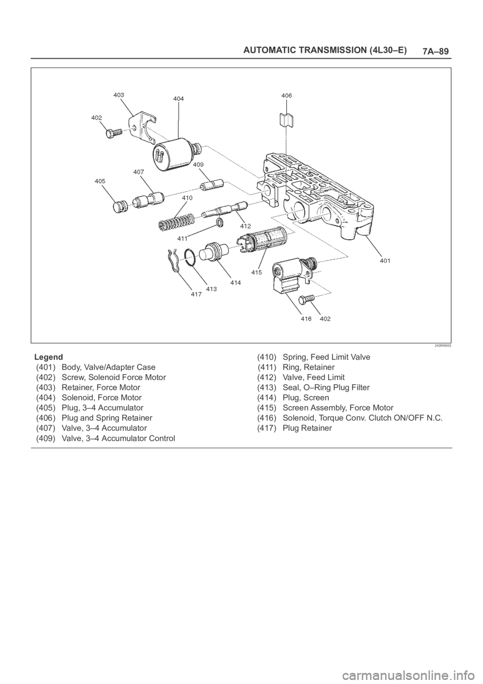
243RW003
Legend
(401) Body, Valve/Adapter Case
(402) Screw, Solenoid Force Motor
(403) Retainer, Force Motor
(404) Solenoid, Force Motor
(405) Plug, 3–4 Accumulator
(406) Plug and Spring Retainer
(407) Valve, 3–4 Accumulator
(409) Valve, 3–4 Accumulator Control(410) Spring, Feed Limit Valve
(411) Ring, Retainer
(412) Valve, Feed Limit
(413) Seal, O–Ring Plug Filter
(414) Plug, Screen
(415) Screen Assembly, Force Motor
(416) Solenoid, Torque Conv. Clutch ON/OFF N.C.
(417) Plug Retainer
Page 5783 of 6000

7A–2 AUTOMATIC TRANSMISSION (AW30-40LE)
VALVE BODY ASSEMBLY AND PRESSERE CONTOROL SOLENOID . . . . . . . . . . . . . . . . . . . . . . . . 7A–84
TRANSMISSION REMOVAL AND INSTALLATION. . . . . . . . . . . . . . . . . . . . . . . . . . . . . . . . . . . . . . . . . 7A–86
UNIT REPAIR . . . . . . . . . . . . . . . . . . . . . . . . . . . . . . . . . . . . . . . . . . . . . . . . . . . . . . . . . . . . . . . . . . . . . . . 7A–91
DISASSEMBLY OF MAJOR COMPONENTS . . . . . . . . . . . . . . . . . . . . . . . . . . . . . . . . . . . . . . . . . . . . . 7A–91
DISASSEMBLY, INSPECTION AND REASSEMBLY OF MINOR COMPONENTS. . . . . . . . . . . . . . . . . 7A–107
OIL PUMP . . . . . . . . . . . . . . . . . . . . . . . . . . . . . . . . . . . . . . . . . . . . . . . . . . . . . . . . . . . . . . . . . . . . . . . . 7A–108
OD PLANETARY GEAR AND OD DIRECT CLUTCH ASSEMBLY (C-0) . . . . . . . . . . . . . . . . . . . . . . . . 7A–114
OD SUPPORT ASSEMBLY . . . . . . . . . . . . . . . . . . . . . . . . . . . . . . . . . . . . . . . . . . . . . . . . . . . . . . . . . . . 7A–126
DIRECT CLUTCH ASSEMBLY (C-2) . . . . . . . . . . . . . . . . . . . . . . . . . . . . . . . . . . . . . . . . . . . . . . . . . . . . 7A–133
FORWARD CLUTCH ASSEMBLY (C-1) . . . . . . . . . . . . . . . . . . . . . . . . . . . . . . . . . . . . . . . . . . . . . . . . . 7A–141
FRONT PLANETARY GEAR . . . . . . . . . . . . . . . . . . . . . . . . . . . . . . . . . . . . . . . . . . . . . . . . . . . . . . . . . . 7A–150
PLANETARY SUN GEAR AND NO.1 ONE–WAY CLUTCH . . . . . . . . . . . . . . . . . . . . . . . . . . . . . . . . . . 7A–153
SECOND BRAKE ASSEMBLY (B–2) . . . . . . . . . . . . . . . . . . . . . . . . . . . . . . . . . . . . . . . . . . . . . . . . . . . . 7A–158
REAR PLANETARY GEAR ASSEMBLY AND OUTPUT SHAFT. . . . . . . . . . . . . . . . . . . . . . . . . . . . . . . 7A–163
FIRST AND REVERSE BRAKE (B–3) . . . . . . . . . . . . . . . . . . . . . . . . . . . . . . . . . . . . . . . . . . . . . . . . . . . 7A–171
TRANSMISSION CASE . . . . . . . . . . . . . . . . . . . . . . . . . . . . . . . . . . . . . . . . . . . . . . . . . . . . . . . . . . . . . . 7A–177
TORQUE CONVERTER . . . . . . . . . . . . . . . . . . . . . . . . . . . . . . . . . . . . . . . . . . . . . . . . . . . . . . . . . . . . . . 7A–181
REASSEMBLY OF MAJOR COMPONENTS . . . . . . . . . . . . . . . . . . . . . . . . . . . . . . . . . . . . . . . . . . . . . . 7A–182
MAIN DATA AND SPECIFICATIONS . . . . . . . . . . . . . . . . . . . . . . . . . . . . . . . . . . . . . . . . . . . . . . . . . . . . . 7A–207
GENERAL SPECIFICATIONS . . . . . . . . . . . . . . . . . . . . . . . . . . . . . . . . . . . . . . . . . . . . . . . . . . . . . . . . . 7A–207
TORQUE SPECIFICATIONS . . . . . . . . . . . . . . . . . . . . . . . . . . . . . . . . . . . . . . . . . . . . . . . . . . . . . . . . . . 7A–208
SPECIAL TOOLS . . . . . . . . . . . . . . . . . . . . . . . . . . . . . . . . . . . . . . . . . . . . . . . . . . . . . . . . . . . . . . . . . . . . 7A–211
CAUTION: When fasteners are removed, always
reinstall them at a the same location from which
they were removed. If a fastener needs to be
replaced, use the correct part number fastener for
that application. If the correct part number fastener
is not available, a fastener of equal size and
strength (or stronger) may be used. Fasteners that
are not reused, and those requiring thread locking
compound, will be called out. The correct torque
values must be used when installing fasteners that
require torque. If the above conditions are not
followed, parts or system damage could result.
Page 5801 of 6000

7A–20 AUTOMATIC TRANSMISSION (AW30-40LE)
Once the test vehicle has been identified an “Application
(Power train) Menu" screen appears. Please select the
appropriate application.
The following table shows, which functions are used for
the available equipment versions.
Diagnostic Trouble Codes
The purpose of the “Diagnostic Trouble Codes" mode is
to display stored TCM trouble codes.
When “Diagnostic Trouble Codes" is selected an
“Application Menu" screen appears.
Clear DTC Information
The purpose of the “Clear DTC Information" mode is to
command the clearing of stored TCM trouble codes.
When “Clear DTC Information" is selected, a “Clear
DTC Information", warning screen appears. This screen
informs you that by cleaning DTC's, “all stored DTC
information in controller will be erased".
Do you want to clear DTC's (Yes/No).
Press either the Yes or No key when answering.
After clearing codes, confirm system operation by test
driving the vehicle.
Allow the vehicle to shift through all four forward gears in
a manner which attempts to repeat the failure condition.
NOTE: When the trouble has not been repaired and thetrouble code cannot be erased, check the vehicle again.
DTC Information
When “DTC Information" is selected, an “Application
Menu" appears with a list of DTC information function
keys addressing DTC specifics and their origins.
Function key selections may vary for particular vehicle
and/or system.
Data Display
The purpose of the “Data Display" mode is to
continuously monitor data parameters.
The current actual values of all impor tant sensors and
signals in the system are display through F1 mode.
When “Data Display" is selected an “Application Menu"
appears.
See “TRANSMISSION DATA" and “TCC DATA” on next
page.
Snapshot
When “Snapshot" is selected an “Application Menu"
appears.
When “Transmission Snapshot" application is selected
from the “Application Menu", a “Snapshot Menu"
appears, displaying several options. “Snapshot" options
may vary from one system to another.
“Snapshot" allows a recording of all vehicle parameters.
There parameters may then be replayed at a future
point in time.
This action allows you to focus on making the condition
occur, rather than trying to view all of the data in
anticipation of the fault. The snapshot will collect
parameter information around a trigger point that you
select.
When a snapshot is taken. It is recorded onto the
PCMCIA memory card. When the Tech2 is powered
down. Snapshots are not lost.
Actuator Tests
The purpose of “Actuator Tests" mode is to check for
correct operation of electronic system actuators.
Lamps
You can operate the lamps by pressing the ON and OFF
buttons.
Preconditions: P or N position
Solenoid
Solenoid S1(1-2/3-4), S2(2-3) and TCC Solenoid
(Torque Converter Clutch)
You can operate the solenoids by pressing the ON and
OFF buttons.
Preconditions: P or N position, no vehicle speed, no
engine speed
Pressure Control Solenoid (PCS)
You can operate the PC Solenoid by pressing the ON
and OFF buttons. ON will command a maximum current
of 1000 mA and OFF a minimum of 200 mA.
Preconditions: P or N position, no vehicle speed, engine
running F0: Diagnostic Trouble Codes
F0: Read DTC Info Ordered By Priority
F1: Clear DTC Information
F2: DTC Information
F0: History
F1: MIL SVS or Message Requested
F2: Last Test Failed
F3: Test Failed Since Code Cleared
F4: Not Ran Since Code Cleared
F5: Failed This Ignition
F1: Data Display
F0: Transmission Data
F1: TCC Data
F2: Snapshot
F3: Actuator Tests
F0: Lamps
F0: Check Light Test
F1: Power Lamp Test
F2: Winter Lamp Test
F3: AT Oil Temperature Lamp Test
F1: Solenoids
F0: Solenoid 2-3 Test
F1: Solenoid 1-2/3-4 Test
F2: TCC Solenoid Test
F3: Pressure Control Solenoid (PCS)
Page 5802 of 6000

AUTOMATIC TRANSMISSION (AW30-40LE) 7A–21
TRANSMISSION DATA
Item Unit Enigne running at idle
Current Gear1
Lock Up Inactive, Active Inactive
Selector PositionPar k
AT Output Speed (Automatic Transmission) RPM 0 RPM
Output Speed (Meter Signal Side) RPM 0 RPM
AT Input Speed (Automatic Transmission) RPM 0 RPM
Engine Speed RPM 695
745 RPM
Vehicle Speed (Output Side) km/h 0 km/h
Throttle Position % 0 %
Throttle Position Sensor V 0.25
0.45V
AT Oil Temperature (Automatic Transmission)
C, F70 80C (158 176F)
Shift Pattern
Desired PCS Pressure (Pressure Control Solenoid) kPa
PCS Desired Current (Pressure Control Solenoid) mA
PCS Actual Current (Pressure Control Solenoid) mA
Overdrive Off Switch Off, On
Brake Switch Open 0V, Closed 12V Closed 12V
Winter Switch Open, Closed 0V Open
Power Switch Open, Closed 0V Open
Diagnostic Request Open, Closed Open
Winter Lamp Inactive 12V, Active 0V Inactive 12V
Power Lamp Inactive 12V, Active 0V Inactive 12V
Check Light Inactive 12V, Active 0V Inactive 12V
AT Oil Temperature Lamp (Automatic Transmission) Inactive 12V, Active 0V Inactive 12V
Solenoid 2-3 Inactive 0V, Active 12V Inactive 0V
Solenoid 1-2/3-4 Inactive 0V, Active 12V Active 12V
TCC Solenoid (Torque Conver ter Clutch) Inactive 0V, Active 12V Inactive 0V
Page 5806 of 6000

AUTOMATIC TRANSMISSION (AW30-40LE) 7A–25
DIAGNOSTIC TROUBLE CODES (DTC) CHECK
DTC
NUMBERFLASHING
CODEDESCRIPTION
P0120 21 ANALOG THROTTLE SIGNAL FAILURE (VTH)
P0502 24 SPEED METER SENSOR FAILURE (SP1)
P0705 17 GEAR SELECTOR FAILURE (PRND2L)
P0710 16 OIL TEMPERATURE SENSOR FAILURE (OT2)
P0717 14 INPUT REVOLUTION SENSOR FAILURE (NC0)
P0722 11 OUTPUT REVOLUTION SENSOR FAILURE (SP2)
P0727 13 ENGINE REVOLUTION SIGNAL FAILURE (NE)
P0743 33 TORQUE CONVERTER CLUTCH CONTROL LOCK-UP (ON/OFF) SOLENOID
FA I L U R E ( S L )
P0748 35 PRESSURE CONTROL SOLENOID FAILURE (STH)
P0753 31 SOLENOID 1 FAILURE (S1)
P0758 32 SOLENOID 2 FAILURE (S2)
P1121 23 ANALOG THROTTLE SIGNAL FAILURE (VREF, VGND)
Page 5821 of 6000

7A–40 AUTOMATIC TRANSMISSION (AW30-40LE)
DTC P0743 (FLASHING CODE 33) TORQUE CONVERTER CLUTCH CONTROL LOCK-UP (ON/
OFF) SOLENOID FA I L U R E ( S L )
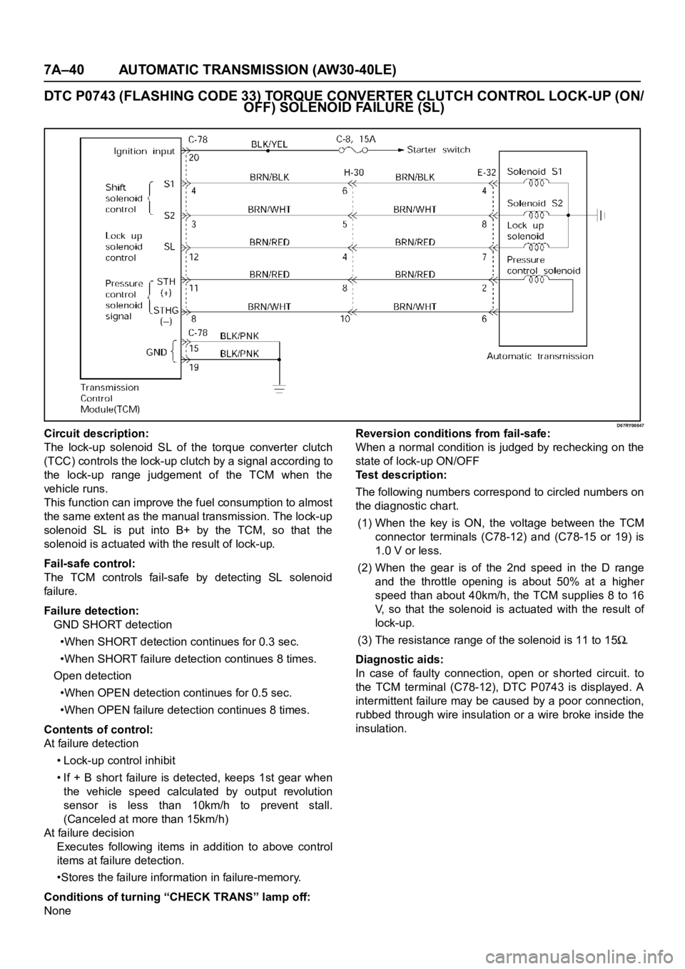
D07RY00047Circuit description:
The lock-up solenoid SL of the torque converter clutch
(TCC) controls the lock-up clutch by a signal according to
the lock-up range judgement of the TCM when the
vehicle runs.
This function can improve the fuel consumption to almost
the same extent as the manual transmission. The lock-up
solenoid SL is put into B+ by the TCM, so that the
solenoid is actuated with the result of lock-up.
Fail-safe control:
The TCM controls fail-safe by detecting SL solenoid
fai lu re.
Failure detection:
GND SHORT detection
•When SHORT detection continues for 0.3 sec.
•When SHORT failure detection continues 8 times.
Open detection
•When OPEN detection continues for 0.5 sec.
•When OPEN failure detection continues 8 times.
Contents of control:
At failure detection
• Lock-up control inhibit
• If + B short failure is detected, keeps 1st gear when
the vehicle speed calculated by output revolution
sensor is less than 10km/h to prevent stall.
(Canceled at more than 15km/h)
At failure decision
Executes following items in addition to above control
items at failure detection.
•Stores the failure information in failure-memory.
Conditions of turning “CHECK TRANS” lamp off:
NoneReversion conditions from fail-safe:
When a normal condition is judged by rechecking on the
state of lock-up ON/OFF
Test description:
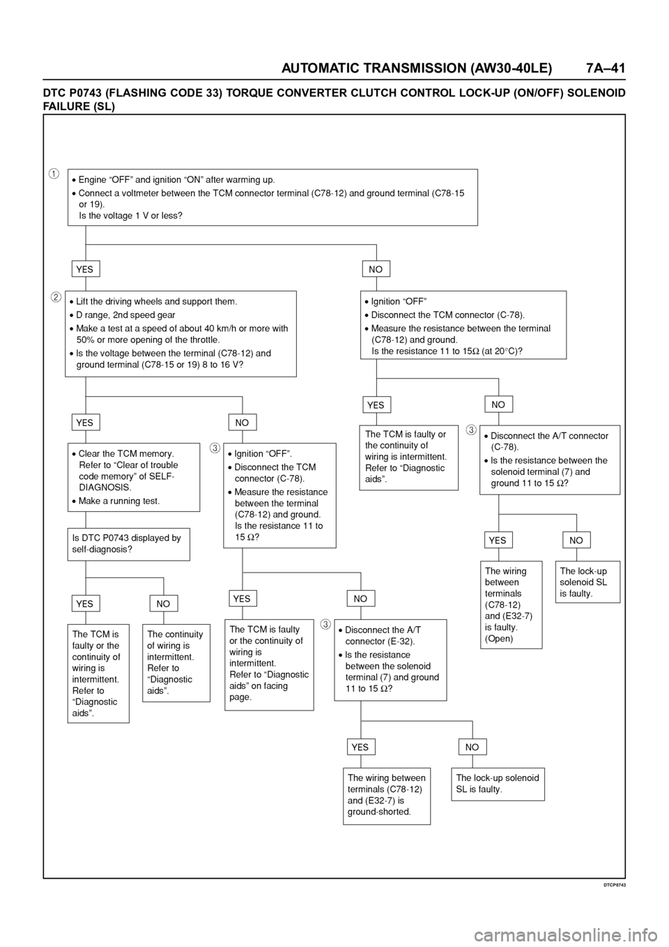
The following numbers correspond to circled numbers on
the diagnostic char t.
(1) When the key is ON, the voltage between the TCM
connector terminals (C78-12) and (C78-15 or 19) is
1.0 V or less.
(2) When the gear is of the 2nd speed in the D range
and the throttle opening is about 50% at a higher
speed than about 40km/h, the TCM supplies 8 to 16
V, so that the solenoid is actuated with the result of
lock-up.
(3) The resistance range of the solenoid is 11 to 15
.
Diagnostic aids:
In case of faulty connection, open or shorted circuit. to
the TCM terminal (C78-12), DTC P0743 is displayed. A
intermittent failure may be caused by a poor connection,
rubbed through wire insulation or a wire broke inside the
insulation.
Page 5822 of 6000

AUTOMATIC TRANSMISSION (AW30-40LE) 7A–41
DTC P0743 (FLASHING CODE 33) TORQUE CONVERTER CLUTCH CONTROL LOCK-UP (ON/OFF) SOLENOID
FAILURE (SL)
DTCP0743
Page 5844 of 6000

AUTOMATIC TRANSMISSION (AW30-40LE) 7A–63
F07RY00002
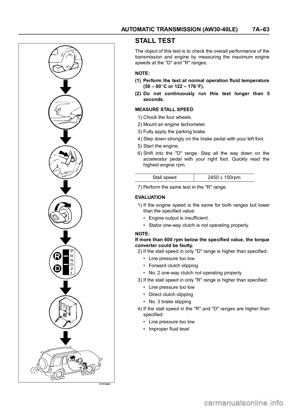
STALL TEST
The object of this test is to check the overall performance of the
transmission and engine by measuring the maximum engine
speeds at the "D" and "R" ranges.
NOTE:
(1) Perform the test at normal operation fluid temperature
(50 – 80
C or 122 – 176F).
(2) Do not continuously run this test longer than 5
seconds.
MEASURE STALL SPEED
1) Chock the four wheels.
2) Mount an engine tachometer.
3) Fully apply the parking brake.
4) Step down strongly on the brake pedal with your left foot.
5) Star t the engine.
6) Shift into the "D" range. Step all the way down on the
accelerator pedal with your right foot. Quickly read the
highest engine rpm.
7) Perform the same test in the "R" range.
EVALUATION
1) If the engine speed is the same for both ranges but lower
than the specified value:
• Engine output is insufficient.
• Stator one-way clutch is not operating properly.
NOTE:
If more than 600 rpm below the specified value, the torque
converter could be faulty.
2) If the stall speed in only "D" range is higher than specified:
• Line pressure too low
• Forward clutch slipping
• No. 2 one-way clutch not operating properly
3) If the stall speed in only "R" range is higher than specified:
• Line pressure too low
• Direct clutch slipping
• No. 3 brake slipping
4) If the stall speed in the "R" and "D" ranges are higher than
specified:
• Line pressure too low
• Improper fluid levelStall speed 2450
150rpm