1998 OPEL FRONTERA engine oil
[x] Cancel search: engine oilPage 5655 of 6000
6E–226
4JX1–TC ENGINE DRIVEABILITY AND EMISSIONS
0018
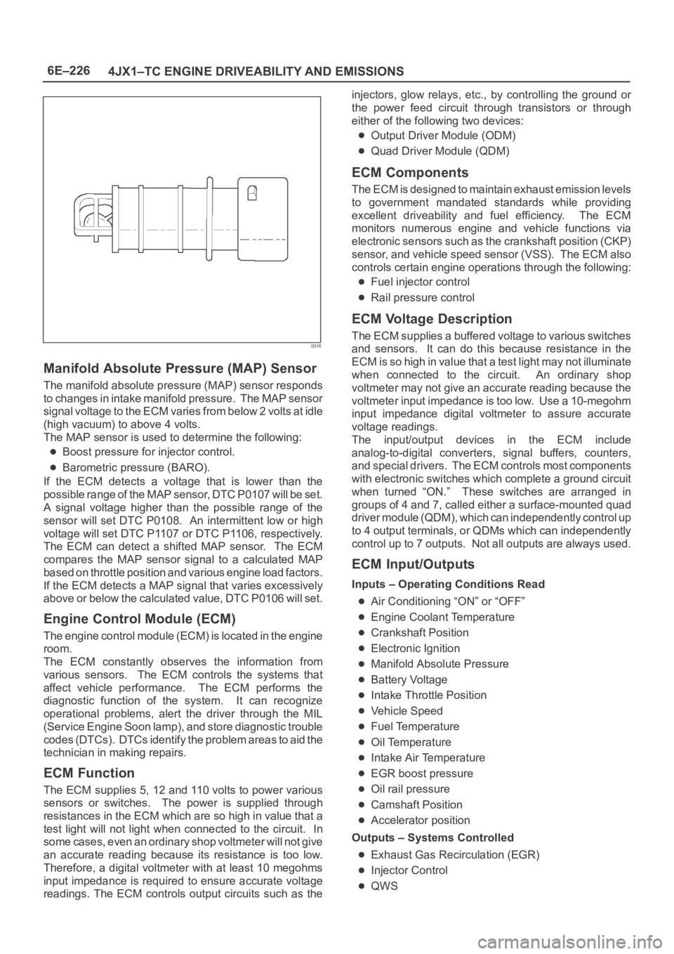
Manifold Absolute Pressure (MAP) Sensor
The manifold absolute pressure (MAP) sensor responds
to changes in intake manifold pressure. The MAP sensor
signal voltage to the ECM varies from below 2 volts at idle
(high vacuum) to above 4 volts.
The MAP sensor is used to determine the following:
Boost pressure for injector control.
Barometric pressure (BARO).
If the ECM detects a voltage that is lower than the
possible range of the MAP sensor, DTC P0107 will be set.
A signal voltage higher than the possible range of the
sensor will set DTC P0108. An intermittent low or high
voltage will set DTC P1107 or DTC P1106, respectively.
The ECM can detect a shifted MAP sensor. The ECM
compares the MAP sensor signal to a calculated MAP
based on throttle position and various engine load factors.
If the ECM detects a MAP signal that varies excessively
above or below the calculated value, DTC P0106 will set.
Engine Control Module (ECM)
The engine control module (ECM) is located in the engine
room.
The ECM constantly observes the information from
various sensors. The ECM controls the systems that
affect vehicle performance. The ECM performs the
diagnostic function of the system. It can recognize
operational problems, alert the driver through the MIL
(Service Engine Soon lamp), and store diagnostic trouble
codes (DTCs). DTCs identify the problem areas to aid the
technician in making repairs.
ECM Function
The ECM supplies 5, 12 and 110 volts to power various
sensors or switches. The power is supplied through
resistances in the ECM which are so high in value that a
test light will not light when connected to the circuit. In
some cases, even an ordinary shop voltmeter will not give
an accurate reading because its resistance is too low.
Therefore, a digital voltmeter with at least 10 megohms
input impedance is required to ensure accurate voltage
readings. The ECM controls output circuits such as theinjectors, glow relays, etc., by controlling the ground or
the power feed circuit through transistors or through
either of the following two devices:
Output Driver Module (ODM)
Quad Driver Module (QDM)
ECM Components
The ECM is designed to maintain exhaust emission levels
to government mandated standards while providing
excellent driveability and fuel efficiency. The ECM
monitors numerous engine and vehicle functions via
electronic sensors such as the crankshaft position (CKP)
sensor, and vehicle speed sensor (VSS). The ECM also
controls certain engine operations through the following:
Fuel injector control
Rail pressure control
ECM Voltage Description
The ECM supplies a buffered voltage to various switches
and sensors. It can do this because resistance in the
ECM is so high in value that a test light may not illuminate
when connected to the circuit. An ordinary shop
voltmeter may not give an accurate reading because the
voltmeter input impedance is too low. Use a 10-megohm
input impedance digital voltmeter to assure accurate
voltage readings.
The input/output devices in the ECM include
analog-to-digital converters, signal buffers, counters,
and special drivers. The ECM controls most components
with electronic switches which complete a ground circuit
when turned “ON.” These switches are arranged in
groups of 4 and 7, called either a surface-mounted quad
driver module (QDM), which can independently control up
to 4 output terminals, or QDMs which can independently
control up to 7 outputs. Not all outputs are always used.
ECM Input/Outputs
Inputs – Operating Conditions Read
Air Conditioning “ON” or “OFF”
Engine Coolant Temperature
Crankshaft Position
Electronic Ignition
Manifold Absolute Pressure
Battery Voltage
Intake Throttle Position
Vehicle Speed
Fuel Temperature
Oil Temperature
Intake Air Temperature
EGR boost pressure
Oil rail pressure
Camshaft Position
Accelerator position
Outputs – Systems Controlled
Exhaust Gas Recirculation (EGR)
Injector Control
QWS
Page 5657 of 6000
6E–228
4JX1–TC ENGINE DRIVEABILITY AND EMISSIONS
General Description (Air Induction)
Air Induction System
The air induction system filters contaminants from the
outside air, and directs the progress of the air as it is
drawn into the engine. A remote-mounted air cleaner
prevents dirt and debris in the air from entering the
engine. The air duct assembly routes filtered air to the
throttle body. Air enters the engine by to following steps:
1. Through the throttle body.
2. Into the intake manifold.
3. Through the cylinder head intake ports.
4. Into the cylinders.
General Description (Fuel Metering)
Deceleration Mode
The ECM reduces the amount of fuel injected when it
detects a decrease in the Accelerator position.
Fuel Injector
Fuel injector comprises the solenoid, hydraulic line, and
fuel line. Fuel injection is controlled by the continuity time
signal and continuity start timing signal from ECM to the
solenoid
ECM determines the running conditions of engine by
input signals such as engine speed. Accelerator throttle
valve opening, and engine coolant temperature, thereby
to send the solenoid the best suited signal to the engine
status. When current is carried to the solenoid, the
armature opens the poppet valve to alow high pressure oil
to run into the injector. Under the pressure of the oil, the
piston and plunger are depressed to compress the fuel in
the combustion chamber of the plunger. Specifically, the
pressure of the fuel compressed is increased by a piston
top/ plunger bottom area ratio over the pressure of high
pressure oil, thereby lifting the fuel nozzle end needle for
injecting fuel.
Fuel Metering System Components
The fuel metering system is made up of the following
parts:
The fuel injectors.
The intake throttle body.
The Accelerator position (AP) sensor
The ECM.
The crankshaft position (CKP) sensor.
The camshaft position (CMP) sensor.
Basic System Operation
Fuel is supplied through fuel filter to the fuel pump.
The fuel pump is installed to the oil pump, and fuel is
forced, through the fuel pump outlet, pipe and cylinder
head inside, into the fuel injector.
An orifice is provided at the rear fuel outlet of cylinder
head to control the pressure of oil.The injector is controlled by ECM which gives
opening/closing commands to the solenoid installed on
the top of the injector. Opening/closing operation of the
pressurized engine oil circuit of the injector controls fuel
injection quantity, fuel injection timing, etc.
A/C Clutch Diagnosis
A/C Request Signal
This signal tells the ECM when the A/C mode is selected
at the A/C control head. The ECM uses this to adjust the
idle speed.
Refer to
A/C Clutch Circuit Diagnosis for A/C wiring
diagrams and diagnosis for A/C electrical system.
General Description Exhaust Gas
Recirculation (EGR) System
EGR Purpose
The exhaust gas recirculation (EGR) system is use to
reduce emission levels of oxides of nitrogen (NOx). NOx
emission levels are caused by a high combustion
temperature. The EGR system lowers the NOx emission
levels by decreasing the combustion temperature.
The ECM uses information from the following sensors to
control EGR valve boost pressure.
ECT
ITP
Engine Speed
AP sensor
Page 5668 of 6000
ENGINE LUBRICATION 6G – 1
ENGINE LUBRICATION
CONTENTS
General Description . . . . . . . . . . . . . . . . . . 6G–2
Lubrication Chart . . . . . . . . . . . . . . . . . . 6G–2
Oil Flow . . . . . . . . . . . . . . . . . . . . . . . . . 6G–3
Oil Pump Specification . . . . . . . . . . . . . . 6G–3
Oil Filter Specification . . . . . . . . . . . . . . . 6G–3
Sub Oil Filter Specification . . . . . . . . . . . 6G–4Oil Pump . . . . . . . . . . . . . . . . . . . . . . . . . . 6G–5
Oil Cooler Assembly . . . . . . . . . . . . . . . . . . 6G–6
Oil Cooler Specification . . . . . . . . . . . . . . 6G–6
Oil Filter . . . . . . . . . . . . . . . . . . . . . . . . . . . 6G–6
Sub Oil Filter . . . . . . . . . . . . . . . . . . . . . 6G–6
Page 5669 of 6000
6G – 2 ENGINE LUBRICATION
GENERAL DESCRIPTION
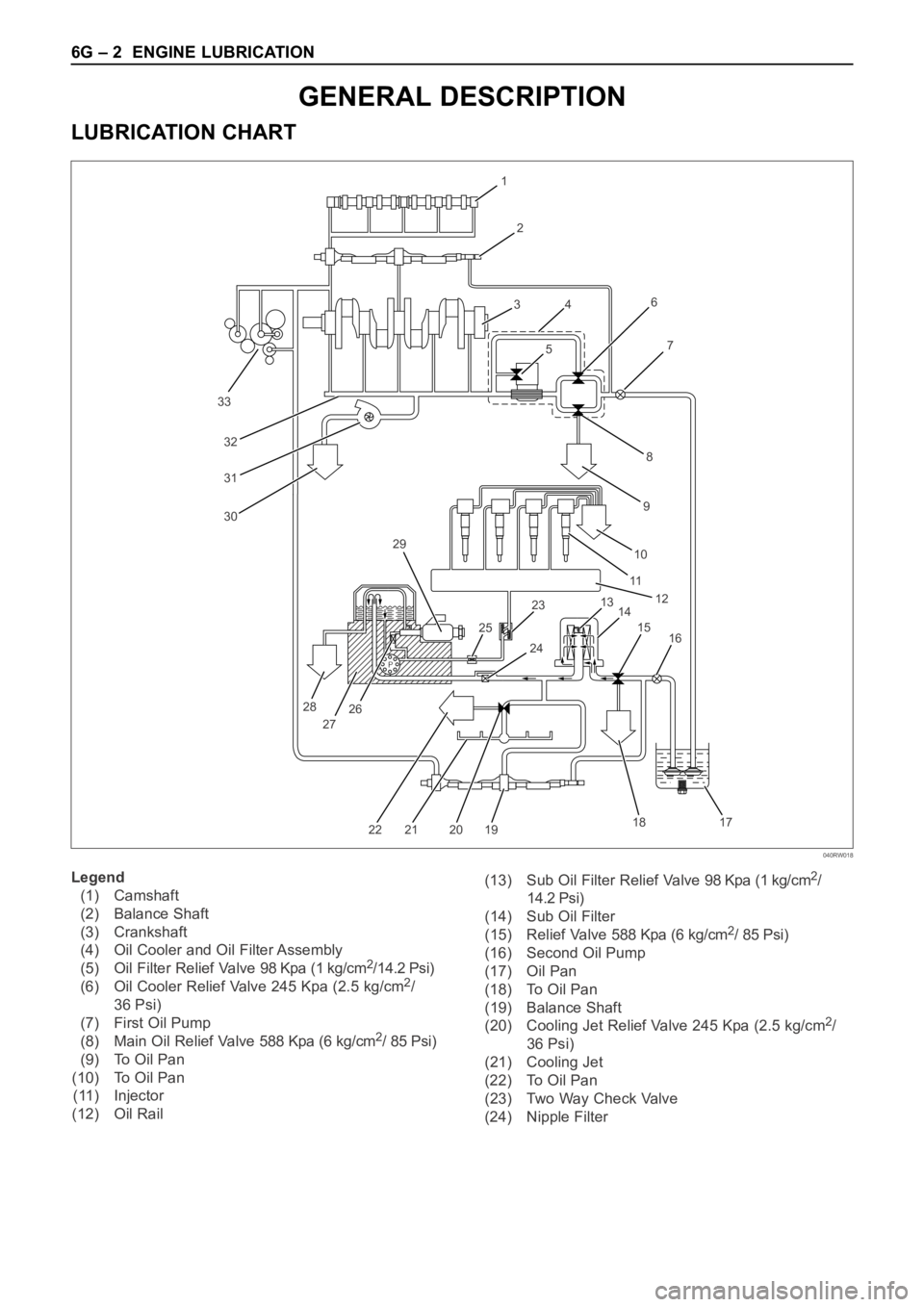
LUBRICATION CHART
P
33
32
31
30
1
2
3
4
56
8
97
10
11
12
13
14 23 29
25
28
27262415
16
17 18
19 20 21 22
Legend
(1) Camshaft
(2) Balance Shaft
(3) Crankshaft
(4) Oil Cooler and Oil Filter Assembly
(5) Oil Filter Relief Valve 98 Kpa (1 kg/cm
2/14.2 Psi)
(6) Oil Cooler Relief Valve 245 Kpa (2.5 kg/cm2/
36 Psi)
(7) First Oil Pump
(8) Main Oil Relief Valve 588 Kpa (6 kg/cm
2/ 85 Psi)
(9) To Oil Pan
(10) To Oil Pan
(11) Injector
(12) Oil Rail(13) Sub Oil Filter Relief Valve 98 Kpa (1 kg/cm
2/
14.2 Psi)
(14) Sub Oil Filter
(15) Relief Valve 588 Kpa (6 kg/cm
2/ 85 Psi)
(16) Second Oil Pump
(17) Oil Pan
(18) To Oil Pan
(19) Balance Shaft
(20) Cooling Jet Relief Valve 245 Kpa (2.5 kg/cm
2/
36 Psi)
(21) Cooling Jet
(22) To Oil Pan
(23) Two Way Check Valve
(24) Nipple Filter
040RW018
Page 5670 of 6000
ENGINE LUBRICATION 6G – 3
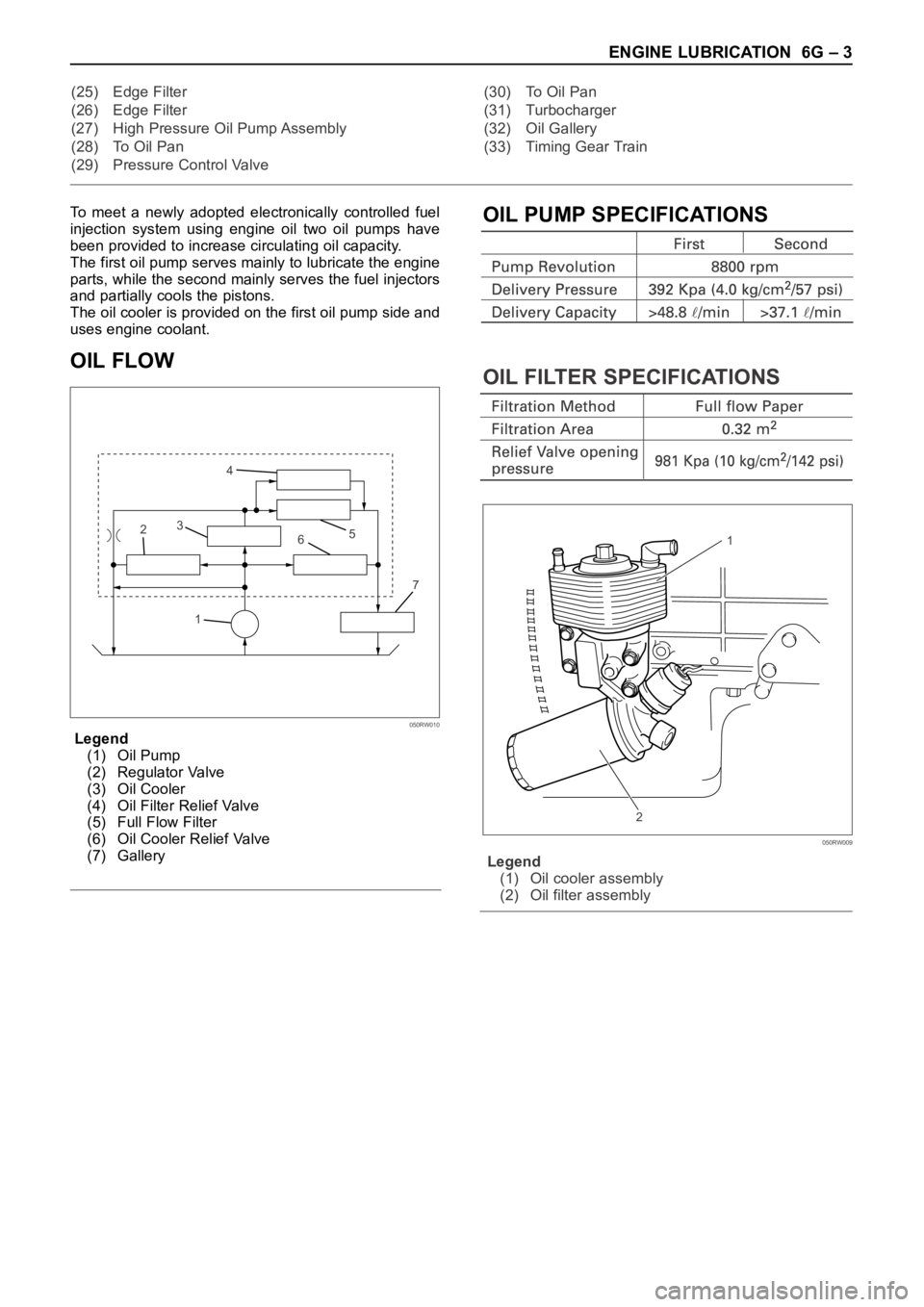
To meet a newly adopted electronically controlled fuel
injection system using engine oil two oil pumps have
been provided to increase circulating oil capacity.
The first oil pump serves mainly to lubricate the engine
parts, while the second mainly serves the fuel injectors
and partially cools the pistons.
The oil cooler is provided on the first oil pump side and
uses engine coolant.
OIL FLOW
Legend
(1) Oil Pump
(2) Regulator Valve
(3) Oil Cooler
(4) Oil Filter Relief Valve
(5) Full Flow Filter
(6) Oil Cooler Relief Valve
(7) Gallery
OIL PUMP SPECIFICATIONS
OIL FILTER SPECIFICATIONS
Legend
(1) Oil cooler assembly
(2) Oil filter assembly (25) Edge Filter
(26) Edge Filter
(27) High Pressure Oil Pump Assembly
(28) To Oil Pan
(29) Pressure Control Valve(30) To Oil Pan
(31) Turbocharger
(32) Oil Gallery
(33) Timing Gear Train
17 65 4
3
2
050RW010
1
2
050RW009
Page 5671 of 6000
6G – 4 ENGINE LUBRICATION
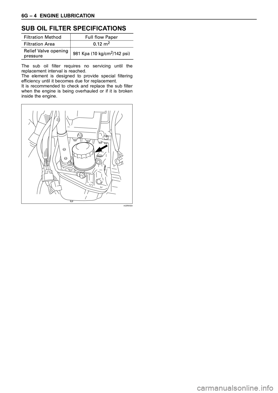
SUB OIL FILTER SPECIFICATIONS
The sub oil filter requires no servicing until the
replacement interval is reached.
The element is designed to provide special filtering
efficiency until it becomes due for replacement.
It is recommended to check and replace the sub filter
when the engine is being overhauled or if it is broken
inside the engine.
442RW004
Page 5672 of 6000
ENGINE LUBRICATION 6G – 5
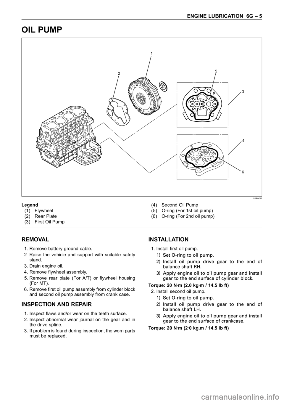
OIL PUMP
REMOVAL
1. Remove battery ground cable.
2 Raise the vehicle and support with suitable safety
stand.
3. Drain engine oil.
4. Remove flywheel assembly.
5. Remove rear plate (For A/T) or flywheel housing
(For MT).
6. Remove first oil pump assembly from cylinder block
and second oil pump assembly from crank case.
INSPECTION AND REPAIR
1. Inspect flaws and/or wear on the teeth surface.
2. Inspect abnormal wear journal on the gear and in
the drive spline.
3. If problem is found during inspection, the worn parts
must be replaced.
INSTALLATION
1. Install first oil pump.
Torque: 20 Nꞏm (2.0 kgꞏm / 14.5 lb ft)
2. Install second oil pump.
Torque: 20 Nꞏm (2ꞏ0 kg.m / 14.5 lb ft)
2
1
5
6
3
4
Legend
(1) Flywheel
(2) Rear Plate
(3) First Oil Pump(4) Second Oil Pump
(5) O-ring (For 1st oil pump)
(6) O-ring (For 2nd oil pump)
012RW097
Page 5673 of 6000
6G – 6 ENGINE LUBRICATION
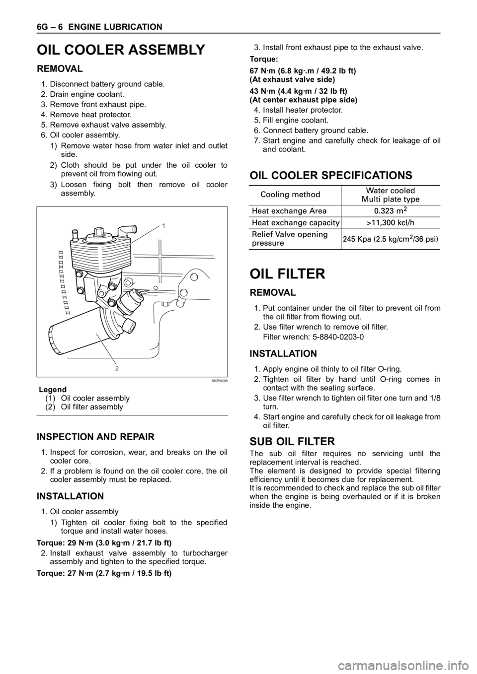
OIL COOLER ASSEMBLY
REMOVAL
1. Disconnect battery ground cable.
2. Drain engine coolant.
3. Remove front exhaust pipe.
4. Remove heat protector.
5. Remove exhaust valve assembly.
6. Oil cooler assembly.
1) Remove water hose from water inlet and outlet
side.
2) Cloth should be put under the oil cooler to
prevent oil from flowing out.
3) Loosen fixing bolt then remove oil cooler
assembly.
Legend
(1) Oil cooler assembly
(2) Oil filter assembly
INSPECTION AND REPAIR
1. Inspect for corrosion, wear, and breaks on the oil
cooler core.
2. If a problem is found on the oil cooler core, the oil
cooler assembly must be replaced.
INSTALLATION
1. Oil cooler assembly
1) Tighten oil cooler fixing bolt to the specified
torque and install water hoses.
Torque: 29 Nꞏm (3.0 kgꞏm / 21.7 lb ft)
2. Install exhaust valve assembly to turbocharger
assembly and tighten to the specified torque.
Torque: 27 Nꞏm (2.7 kgꞏm / 19.5 lb ft)3. Install front exhaust pipe to the exhaust valve.
To r q u e :
67 Nꞏm (6.8 kgꞏ.m / 49.2 lb ft)
(At exhaust valve side)
43 Nꞏm (4.4 kgꞏm / 32 lb ft)
(At center exhaust pipe side)
4. Install heater protector.
5. Fill engine coolant.
6. Connect battery ground cable.
7. Start engine and carefully check for leakage of oil
and coolant.
OIL COOLER SPECIFICATIONS
OIL FILTER
REMOVAL
1. Put container under the oil filter to prevent oil from
the oil filter from flowing out.
2. Use filter wrench to remove oil filter.
Filter wrench: 5-8840-0203-0
INSTALLATION
1. Apply engine oil thinly to oil filter O-ring.
2. Tighten oil filter by hand until O-ring comes in
contact with the sealing surface.
3. Use filter wrench to tighten oil filter one turn and 1/8
turn.
4. Start engine and carefully check for oil leakage from
oil filter.
SUB OIL FILTER
The sub oil filter requires no servicing until the
replacement interval is reached.
The element is designed to provide special filtering
efficiency until it becomes due for replacement.
It is recommended to check and replace the sub oil filter
when the engine is being overhauled or if it is broken
inside the engine.
1
2
050RW009